LSF (Light Steel Framing)
Trusses as plane frames
A roof truss works in its own plane: two chords joined by web posts and diagonals carry the roof weight and the wind down to the walls. This page shows what the engine checks in each piece, where the buckling length of each one comes from and how to read the report of a truss bar.
Overview
In Roof trusses the trusses of the house were placed, Lattice trusses shows the web post and diagonal patterns of a truss, and in Roof the roof was closed with battens and tiles. There the subject was geometry: where each piece is created and how it joins the others. Here it is what the engine checks in it.
To the engine, each truss is a set of bars in a vertical plane. The chords are continuous and split at the nodes. Web posts and diagonals are pinned at the ends. The battens do not enter as bars: the weight they carry reaches the top chord by area, and their position says where that chord is braced.
The example is T2, a common truss of the house: a 7.00 m span between the walls, a 30% pitch and every piece in C 89x41/39x12x0.95, ZAR-280 steel. The numbers come from the calculation of the whole house, on screen: 26 combinations and 1,113 bar segments in the Bar Verification list.

- 7.00 m: span of T2, wall to wall
- 30 %: pitch of both roof slopes
- 0.95 mm: thickness of every truss piece
- 1.00: the highest ratio of T2, in the top chord
What it is for
The load travels in the plane of the truss
The tile rests on the battens, and the battens rest on the top chord. From the chord, the load goes down through the nodes: the web posts and diagonals carry it to the bottom chord and to the supports, on the walls. The wind comes in by the same path, as pressure on the roof slopes. All of this happens in the plane of the truss, and that is the plane where it is strong.
Out of the plane, it is a thin piece that needs bracing. The drawing is the right half of T2, to scale, with what braces each chord and the buckling length the engine gives each piece.
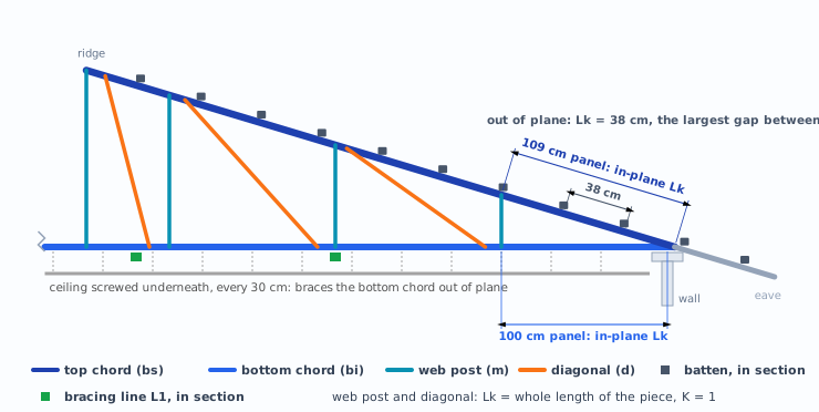
The batten leaves the model. In the calculation, the batten is not a bar. The roof weight and the live load reach the top chord as a distributed load, and the position of each batten is kept to mark where the chord is braced out of the plane.
The ceiling braces the bottom chord. With a ceiling screwed under the truss, the bottom chord is braced out of the plane at each fastener, 30 cm in the house. The bracing line L1, which runs from wall to wall, braces the nodes it crosses.
Each piece with its role and its length
The label of each bar says what it is. That is how you find it in the Bar Verification list, and that is how the engine chooses how to model the piece and where its buckling length comes from.
| Piece | In the label | What it does | How the engine treats it |
|---|---|---|---|
| top chord | bs1, bs2 | The two roof slopes, from the ridge to the eave. It receives the battens. | Continuous, split at the nodes. In the plane, it buckles in the panel; out of it, over the largest gap between battens, purlins or rafters. |
| bottom chord | bi | The straight line from support to support, which holds the spread of the roof slopes. | Continuous. In the plane, the panel; out of it, the largest gap between braced nodes, or the ceiling fastener spacing when that is smaller. |
| web post | m | Upright piece between the two chords. | Pinned at the ends, K = 1: it buckles over the whole piece. |
| diagonal | d | Inclined piece between the two chords. | Pinned at the ends, K = 1: it buckles over the whole piece. |
| cross member | L1:l | The bracing line that ties the bottom chords from one truss to the next, from wall to wall. | Checked as a bar. The nodes where it crosses the bottom chord count as braced. |
| batten | r | Tile support, on the top chord. | Out of the calculation model. Its position gives the length of the top chord out of the plane. |
- 38 cm: largest gap between battens: top chord, out of the plane
- 109 cm: top chord panel: in the plane
- 30 cm: ceiling fastener spacing: bottom chord, out of the plane
- 106 cm: web post m4 and diagonal d3 of T2: the whole piece
How to read the label. TL:TL1:T2:bs2:6 is roof TL1, truss T2, the top chord on side 2 and segment 6 of that chain (the count starts at zero). All the segments of bs2 form a single chord, and the engine recognizes them as a chain.
The web laid flat. In the truss as it is fabricated, the chord lies with its web across, and the strong axis of the section ends up out of the plane. That is why, in the chord report, Lx is the out-of-plane length and Ly is the panel. It is the opposite of a wall stud.
What the standard says
Cold-formed steel, item by item
The truss pieces are cold-formed Ue sections, and the engine checks them by ABNT NBR 14762:2010, the Brazilian standard for cold-formed steel. NBR 16970-2:2022, the Brazilian LSF standard, brings the deflection limit of the chord. The table says which item answers for which check in the bar report.
| Check on screen | Item | What it checks |
|---|---|---|
| Slenderness, compressed bar | 14762, 9.7.4 | The slenderness ratio does not exceed 200. It is a requirement: above that, it fails. |
| Slenderness, tensioned bar | 14762, 9.6.3 | The standard recommends not exceeding 300. The engine reports the value, with ratio 0.00. |
| Tension | 14762, 9.6.2 | The lesser of yielding of the gross section and rupture of the net section. |
| Compression | 14762, 9.7.2 | Axial resistance, with the reduction factor χ for global buckling. |
| Flexure, strong and weak axis | 14762, 9.8.2 | Moment resistance: the least of yield onset, lateral-torsional buckling and distortional buckling. |
| Shear | 14762, 9.8.3 | Shear resistance of the web. |
| Flexo-compression and flexo-tension | 14762, 9.9 | The axial force and both moments at the same time: the sum of the three terms does not exceed 1.0. |
| Section yielding (linear) | 14762, 9.9 | The same sum, on the section, without the moment amplification. |
| Deflection | 16970-2, 8.2 | Table 3: the truss chord enters as a roof beam, L/250. |
NBR 14762:2010 · 9.6.3 and 9.7.4.
For a compressed bar, the slenderness ratio should not exceed 200. For a tensioned one, the standard recommends not exceeding 300. The difference shows up in the truss, where half the web members compress and half pull: the engine enforces the first and reports the second.
NBR 16970-2:2022 · 8.2.
Table 3 gives the displacement limits of the LSF pieces. The top and bottom chords of the truss sit on the line of the roof beams: L/250.
One combination at a time. Slenderness is checked in each combination. The diagonal that pulls under the weight can compress under uplift wind, and then the 200 applies, in the combination where it compresses. The page Reading the results teaches how to read the combination codes.
Two checks weigh more in the truss. In the top chord, flexo-compression: it is compressed by the truss and, at the same time, bent between the nodes by the weight of the battens and tiles. In the web members, slenderness: they are straight pieces, with a small axial force and the whole length as buckling length.
Design recommendation
1. Read the top chord by the panel
With the web laid across, the gap between battens falls on the strong axis of the section. In T2, 38 cm give a slenderness of 10.7 out of the plane. In the plane, the 109 cm panel with the weak axis gives 72.4. What limits the top chord is the panel, and what shortens the panel is one more web post or one more diagonal.
2. Screw the ceiling to the truss
Without a ceiling, the bottom chord is braced only at the braced nodes: the wall it rests on, the diaphragm and the bracing line. With the ceiling screwed underneath, the bracing drops to the fastener spacing, 30 cm in the house.
3. Look at the web members by slenderness
Web posts and diagonals carry little force and buckle over the whole piece. In T2, the compressed web post stays at 0.35 by slenderness, and that is also the worst web post and the worst diagonal of the house. A long piece in the middle of the truss is the first one to check.
4. Thickness does not fix slenderness
Slenderness is the length divided by the radius of gyration, and thickness barely changes the radius. To lower slenderness, shorten the piece or change the section.
5. Read the truss by its worst segment
The chord is split into one segment per panel, and each has its own ratio. The utilization of the truss is that of the worst segment.
| If the truss fails by | Change |
|---|---|
| flexo-compression in the top chord | section or thickness of the truss class, or trusses closer together, with less roof for each one |
| slenderness of the top chord | a shorter panel: more web posts and diagonals |
| slenderness of the compressed web post or diagonal | a shorter piece, or a section with a larger radius of gyration |
| slenderness of the bottom chord | a screwed ceiling, or a bracing line |
The section belongs to the class. The roof pieces have no section of their own: they use the class section. Changing the section of the Tesoura comum (common truss) class changes that of every chord, web post and diagonal of the common trusses at once. Step 7 shows that change.
Step by step
1. Calculate and look at the truss from the side
With the house complete, press Calculate. Then rotate the 3D until you look at the roof along the ridge: the trusses appear from the side, one behind the other, with the nearest in front.

2. Turn on the colors
On the results card, the first button, with a green ✓ and a red ×, shows the OK/FAIL colors on the bars; hovering over it, the tooltip says Verification Colors. On the first calculation of the project, they turn on by themselves. Green passes, red fails. In T2, every piece comes out green, and the figure in the overview is this same view with the colors on.
With the colors on, a click reads. In this mode, clicking a bar opens its report instead of selecting it. To go back to editing, turn the colors off with the same button.
Green does not say how much is left. A piece at 0.99 is as green as one at 0.10. To know the margin, open the report or the list: that is what the next steps do.
3. Click the top chord and read the report
With the colors on, click the top chord of T2, on the right side, in the last panel before the support. The Bar Diagnostic Report opens: the header gives the piece, the section, the length and the governing check; further down come the forces at the ends and the loads that reach it, one per load case.


- 1.00: flexo-compression, the governing check, in CB2
- 10.5 kN: compression, against 24.3 kN of resistance
- 17.9 kN·cm: moment about the weak axis, against 37.8
- 72.4: slenderness, out of a maximum of 200
CB2 is the weight combination: the self-weight, the roof weight and the live load, all multiplied by 1.4. In the loads of the report, every load reaching this segment is distributed and lies in the plane of the truss: the roof weight, the live load and the wind. That is why the moment is about the weak axis, the in-plane one, and the moment about the strong axis is practically zero.
4. Open the Bar Verification list
On the same results card, the Bar Verification button opens the list of every calculated segment, with the label, the section, the ratio and the combination. Click a row and it expands into one row per check.
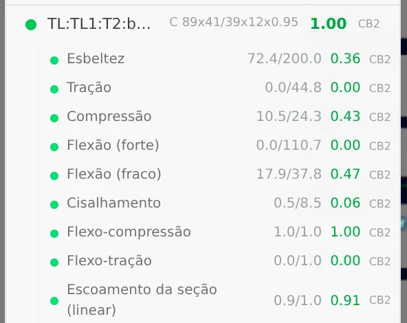
| Check | In the list | What it says |
|---|---|---|
| Slenderness | 72.4 of 200 | the panel, about the weak axis |
| Compression | 10.5 of 24.3 kN (0.43) | the truss force |
| Flexure, strong axis | 0.0 of 110.7 kN·cm | nothing out of the plane |
| Flexure, weak axis | 17.9 of 37.8 kN·cm (0.47) | the weight between the nodes |
| Shear | 0.5 of 8.5 kN (0.06) | ample margin |
| Flexo-compression | 1.00, in CB2 | the sum, with the amplified moment |
| Section yielding | 0.91, in CB2 | the same sum, without amplification |
Compression alone uses 0.43 of the resistance, and weak-axis flexure, 0.47. Added up, they would give 0.90, close to the 0.91 of section yielding, which is that sum on the section, without buckling. Flexo-compression goes beyond that because the engine amplifies the moment, as step 5 shows.
Tension at 0.00 in the top chord. The top chord compresses in the weight combinations. The tension row shows the resistance, 44.8 kN, and zero demand in the governing combination. With suction wind, the force can reverse, and the engine checks both.
5. Read the flexo-compression card and the slenderness card
In the report, each check has a card with the resistances, the demands, the standard item and the combination. The two that explain the top chord are these.
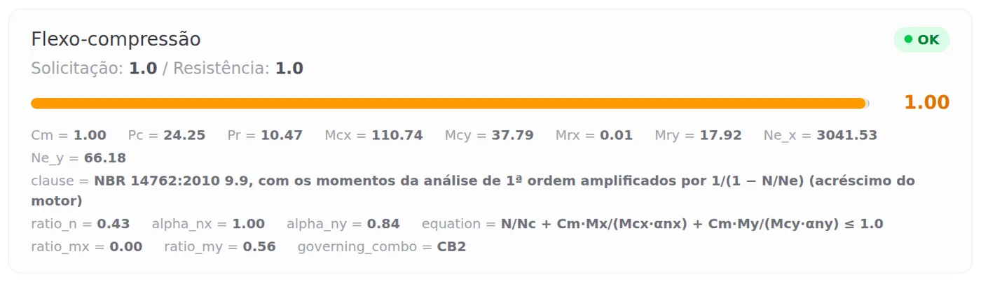
The axial term is Pr/Pc = 10.47/24.25 = 0.43. The weak-axis term is the moment divided by the resistance and by αny = 1 − Pr/Ney = 1 − 10.47/66.18 = 0.84: 17.92/(37.79 × 0.84) = 0.56. The sum is 0.995. The card shows 1.00 rounded, and OK, because it does not reach 1. The chord passes with half a percent of margin.

The Ney of 66.18 kN comes from the same 109 cm panel about the weak axis. It is what makes the amplification grow: the closer the compression gets to Ney, the smaller αny and the larger the moment term. Shortening the panel or thickening the section raises Ney; the trial in step 7 shows how much.
6. Click the bottom chord, a web post and a diagonal
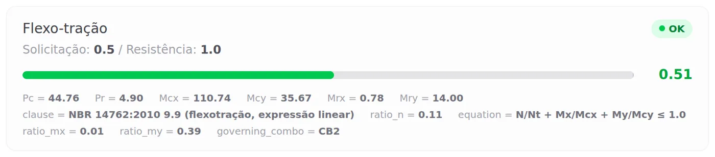
The bottom chord of T2 is in tension. In segment TL:TL1:T2:bi:15, 1.00 m long, slenderness comes with Lx = 30 cm, the ceiling fastener spacing, and Ly = 100 cm, the panel. The item is 9.6.3: tensioned bar, value reported, ratio 0.00. Flexo-tension governs, at 0.51: tension uses 0.11 and the moment from the weight it carries, 0.39.

Web post TL:TL1:T2:m4:0 and diagonal TL:TL1:T2:d3:0 have almost the same length, 106 cm, and the same section. Slenderness comes out equal in both, 70.6. The difference is the force: in CB2 the web post compresses and the diagonal pulls.


| Piece of T2 | Governs | Ratio | Why |
|---|---|---|---|
| top chord, bs2:6 | flexo-compression | 1.00 (0.995) | truss compression and weight between the nodes |
| bottom chord, bi:15 | flexo-tension | 0.51 | tension and the weight hanging from it |
| web post, m4:0 | slenderness | 0.35 | 106 cm in compression, K = 1 |
| diagonal, d3:0 | tension | 0.06 | 2.8 of 44.8 kN; slenderness only reports |
The deflection: the limit and how it is measured
The top and bottom chords of the truss have a deflection limit of L/250, the roof beam line of Table 3. L is that of the segment: the panel between two nodes. Deflection is measured in each segment, not in the whole truss.
Measuring in the segment calls for care with what counts. Under weight and wind, the whole truss moves: the supports go down with the walls, the nodes travel. That movement is not bending of the chord. That is why the engine draws the chord line between the two ends of the segment, already displaced, and measures the deflection from it.
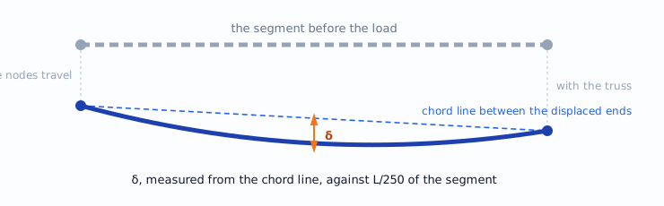
- L/250: limit of the chord, top and bottom
- 4.4 mm: limit of segment bs2:6, 1.09 m long
- 0.26 mm: deflection of that segment, relative to the chord line
- 28 mm: L/250 of the 7.00 m span, to check by hand
The whole span, by hand. The per-segment check says whether the chord bends between the nodes. The sag of the whole truss at midspan is checked by hand, as in Roof trusses: L/250 over the 7.00 m of T2, or 28 mm, compared with the displacement of the ridge node relative to the supports.
Trial: the same section, at 1.15 mm
7. Change the thickness of the Tesoura comum class and calculate
The roof pieces use the class section, and the class is changed in the Classes panel, which is hidden in LSF mode. Switch to the Structure tab, open Classes and click the Tesoura comum row. In the form, open the Profile, choose Dob and the C family and search for 89x41 1.15. Choose C 89x41/39x12x1.15, press Save, go back to the LSF tab and calculate.
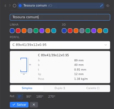
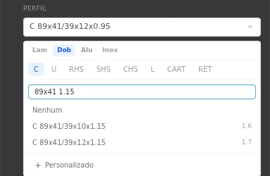

| In T2, read on the cards | At 0.95 mm | At 1.15 mm |
|---|---|---|
| top chord, flexo-compression | 0.995 | 0.81 |
| axial term, Pr/Pc | 10.47/24.25 = 0.43 | 10.62/30.77 = 0.35 |
| weak-axis term | 0.56 (αny = 0.84) | 0.46 (αny = 0.86) |
| bottom chord, flexo-tension | 0.51 | 0.43 |
| web post m4, slenderness | 0.35 | 0.36 |
The resistance went up more than the demand, which grew a little with the self-weight of the thicker pieces. The margin of the chord went from half a percent to 19%. The web post did not improve: slenderness is geometry, and the radius of gyration of the thicker section is practically the same.
Undo the trial before saving. To go back, return the Tesoura comum class to C 89x41/39x12x0.95 by the same path and calculate again. If the change is meant to stay, it applies to every common truss, and the cost of the steel goes up with it.
Shortcuts
- Ctrl+Enter
Calculate the project
Sends the project to the engine, like the Calculate button.
- Home
3D view
Goes to 3D at the last camera pose. With the wall view open, closes it.
Common mistakes
What tends to mislead in the truss
- Reading 1.00 as a failure. The top chord of T2 gives 0.995. The screen shows 1.00, rounded, and OK. It passes, but with no margin: any heavier tile or wider truss spacing takes it to red.
- Tightening the battens to save the top chord. With the web laid across, the gap between battens works on the strong axis, and gives a slenderness of 10.7. What governs is the panel, about the weak axis, at 72.4.
- Thickening the sheet to fix slenderness. From 0.95 to 1.15 mm, web post m4 went from 0.35 to 0.36. Slenderness is fixed with a shorter piece or a larger section.
- Assuming the tensioned diagonal never compresses. The 0.00 slenderness ratio holds for the combination where it pulls. With suction wind the force can reverse, and the engine enforces the 200 in the combination where it compresses.
- Expecting the change to stay in one truss. The section of the roof pieces is the class section. Changing the Tesoura comum class changes every chord, web post and diagonal of the common trusses. The Tesoura de oitão (gable truss) and the Travamento do banzo (bottom chord bracing) have their own classes and do not change with it.
- Looking for the batten in the list. The batten is not checked: it leaves the calculation model, and the weight it carries reaches the chord by area. Its position is what counts, in the buckling length of the top chord.
What each sign means
| On screen | It means |
|---|---|
| Slenderness with item 9.7.4 | a bar compressed in the governing combination; the limit is 200 and it counts |
| Slenderness with item 9.6.3 and ratio 0.00 | a tensioned bar; the 300 is a recommendation, and the value only reports |
| Lx smaller than Ly in the chord | the web laid across: Lx is the out-of-plane length |
| "amplificados por 1/(1 − N/Ne)" on the card | the first-order moment multiplied by the engine, on the safe side |
What the engine checks
It checks the truss that is drawn
Each truss piece is a bar of the model, checked by NBR 14762 in each of the 26 combinations. The highest ratio of all governs and gives the color of the piece.
| Piece | What the engine checks |
|---|---|
| top chord (bs) | Compression and slenderness (9.7.2 and 9.7.4), with the panel in the plane and, out of it, the largest gap between battens, purlins or rafters; flexure about both axes (9.8.2); shear and moment with shear (9.8.3 and 9.8.4); flexo-compression with the amplified moment (9.9); section yielding; L/250 deflection in each segment, measured from the chord line. |
| bottom chord (bi) | Tension (9.6.2), reported slenderness (9.6.3) and flexo-tension; the compression checks in the combination where it compresses. Out of the plane, the length drops to the ceiling fastener spacing when that is smaller than the gap between braced nodes. L/250 deflection in each segment. |
| web post (m) and diagonal (d) | Pinned, K = 1, over the whole piece: tension or compression and slenderness in each combination, with the 200 limit when the piece compresses and the 300 reported when it pulls. |
| cross member of line L1 | Checked as a bar; the nodes where it crosses the bottom chord count as braced. |
| batten | Out of the model: the weight reaches the top chord by area, and its position gives the length of the top chord out of the plane. |
| all | The scope of the standard (9.1.2, Table 4): width over thickness of each plate element. |
What stays with the designer
- The truss connections: chords, web posts and diagonals to each other and the truss to the wall (see Connections panel).
- Web crippling at the truss bearing on the wall, in the chord and in the track.
- The deflection of the whole span: L/250 over the 7.00 m of T2, or 28 mm, against the sag of the ridge node relative to the supports (see Roof trusses).
- The detailing of the bracing the calculation assumes: battens, purlins or rafters at the drawn spacing, line L1 and the ceiling fastening (see Roof).
Shortcuts
- Ctrl+Enter
Calculate the project
Sends the project to the engine, like the Calculate button.
Summary
Where to read each thing
| I want to know | Where |
|---|---|
| whether the truss passes | the colors, with the truss seen from the side in 3D |
| why a segment has that number | the bar report, by clicking with the colors on |
| every segment of a chord | the Bar Verification list |
| the buckling length about each axis | the Slenderness card of the report: Lx and Ly |
| the deflection of the whole span | by hand: L/250 of the span, as in Roof trusses |
The path, in one line
Calculate → look at the truss from the side in 3D → turn on the colors → click the top chord and read the report → open Bar Verification and check the segments → read the web members by slenderness → check the span by hand → change the class, if needed, and calculate again.
The numbers of T2
- 1.00: top chord, flexo-compression (0.995)
- 0.51: bottom chord, flexo-tension
- 0.35: web post, by slenderness
- 0.81: top chord at 1.15 mm, in the trial