Actions & Loads
In structural engineering, loads are organized into actions — groups that represent the nature and origin of forces acting on the structure. Each action has specific characteristics of magnitude, direction, duration, and probability of occurrence. Understanding actions is essential for correct combinations and safe design.
Self-Weight — SW
The weight of the structure itself: steel profiles, connections, bolts, paint, fire protection. This is a permanent action — always present, with known magnitude and direction (always vertical, downward). CalcSteel calculates self-weight automatically based on the profile cross-section area and steel density (7850 kg/m³).
Formula
PP = γ × A × L
Where γ = 78.5 kN/m³ (steel density), A = cross-section area (m²), L = bar length (m).
In CalcSteel
Self-weight is calculated automatically when running the analysis. No manual input needed — the engine reads each bar's profile and length to generate the gravitational distributed load.
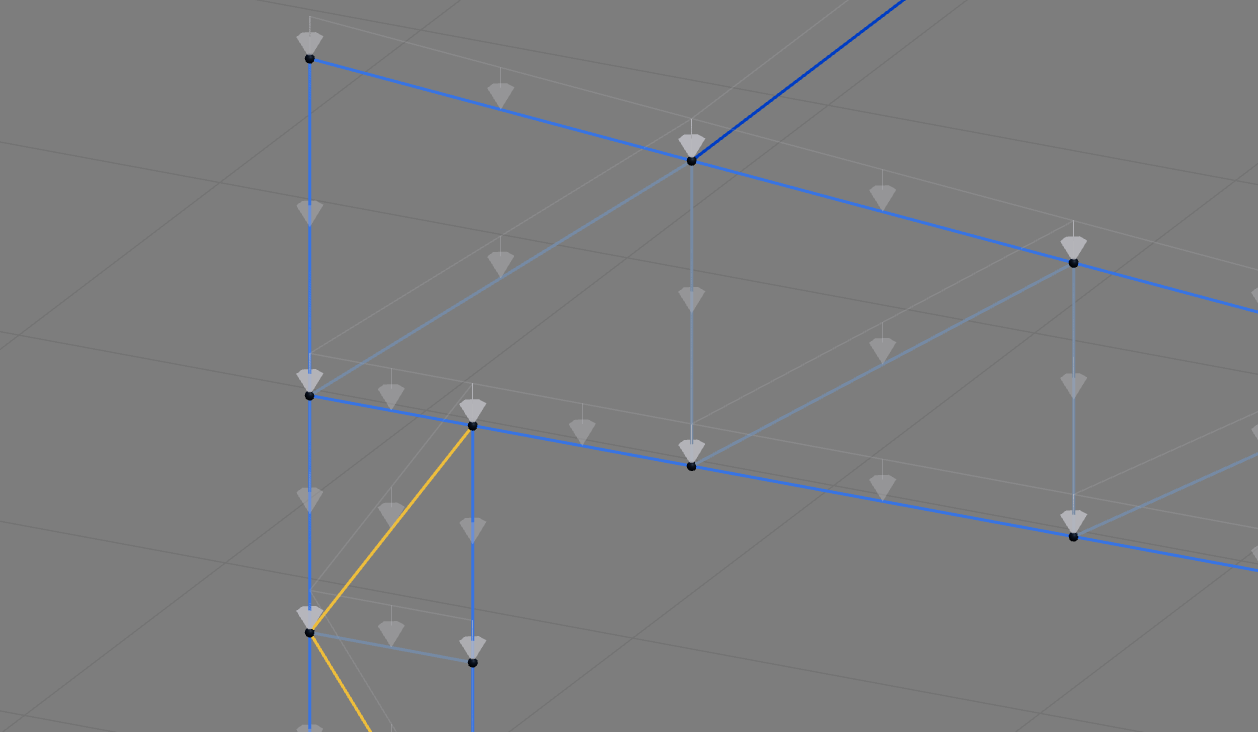
Self-weight arrows automatically generated by CalcSteel on each node, representing the gravitational load of each bar.
Additional Permanent Load — DL
Permanent loads beyond self-weight: roofing, purlins, cladding, mechanical equipment, fixed partitions, ceilings, piping. Defined by the user as distributed loads (kN/m) or area loads (kN/m²), they remain constant throughout the structure's life.
Typical roofing weights
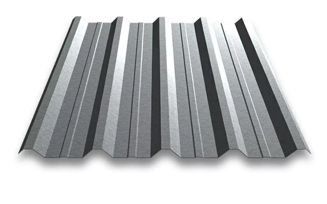 0.10 kN/m²
Steel (trapezoidal)
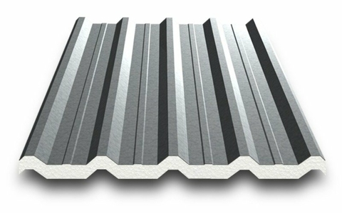 0.15 kN/m²
Thermoacoustic
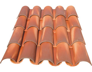 0.65 kN/m²
Ceramic tile
 0.60 kN/m²
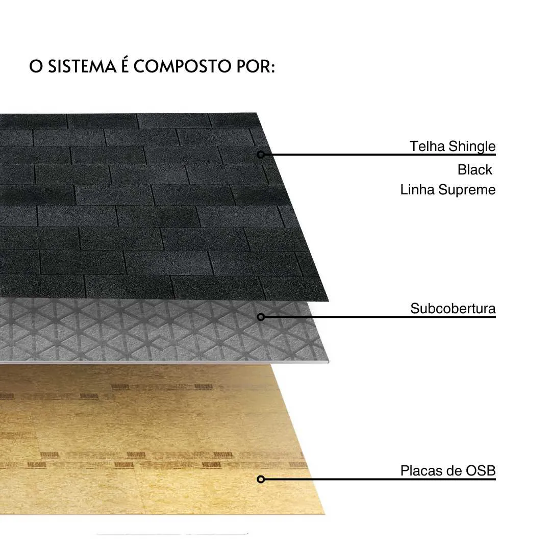
Shingle + OSB
Other permanent loads
- Purlins: 0.05 – 0.15 kN/m²
- Suspended ceiling + services: 0.15 – 0.50 kN/m²
Live Load — LL
Variable loads from occupancy and use: people, furniture, stored materials, vehicles. The magnitude depends on the building use and is defined by standards. Live loads can change position, magnitude, and presence over time.
Typical values
- Inaccessible roofs: 0.50 kN/m² (NBR 6120) / 0.50 kN/m² (Eurocode)
- Offices: 2.0 – 3.0 kN/m²
- Warehouses / storage: 5.0 – 15.0 kN/m²
- Roof maintenance: 1.0 kN concentrated
Wind — W
Wind generates pressure (positive) and suction (negative) on surfaces. The magnitude depends on wind speed (V0), topographic factors, building geometry, and aerodynamic coefficients. Wind is typically the governing action for lightweight steel structures, especially roofs.
Wind dynamic pressure
q = 0.613 × Vk²
Where Vk = V0 × S1 × S2 × S3 (characteristic speed in m/s), q in N/m². Standards: NBR 6123 (Brazil), EN 1991-1-4 (Eurocode), ASCE 7 (USA).
Pressure (windward)
Wind pushes against the windward face of the structure. Positive coefficient (Cpe > 0). Creates compression on the face and increases the global lateral load.
Suction (leeward)
Wind pulls on the leeward face and the roof. Negative coefficient (Cpe < 0). Can lift roofs and reverse support reactions — often the critical condition for lightweight metal roofs.
⚠ Critical for lightweight steel structures
Roof suction can exceed self-weight, causing uplift. Always check anchor bolts and connections for uplift resistance. Many failures in metal buildings are due to insufficient design for wind suction.
Temperature — T
Temperature variations cause thermal expansion/contraction in steel members. For long structures (>40m), thermal effects can generate significant internal forces if the structure is restrained. Common solution: expansion joints or sliding supports at one end.
Thermal coefficient
α = 12 × 10⁻⁶ /°C (steel)
A 30m beam with ΔT=40°C expands 14.4mm. If restrained, it generates axial force N = E × A × α × ΔT.
Seismic — E
Inertial forces induced by earthquake. Applicable in seismic regions and governed by specific standards (NBR 15421, EN 1998, ASCE 7). Typically modeled as equivalent lateral forces or via spectral analysis. Most of Brazil has low seismicity, but it is mandatory for specific structures per NBR 15421.
Load Combinations
Design standards require that loads from different actions be combined using partial safety factors (γ) and combination factors (ψ). The goal is to find the most unfavorable internal force at each section of the structure. Each combination represents a plausible scenario of simultaneous action.
Ultimate Limit State (ULS)
Sd = γg × PP + γg × CP + γq × ψ₀ × SC + γq × ψ₀ × W + ...
Checks structural safety (strength, stability). Uses amplified loads with partial safety factors. The most critical combination governs the design.
Serviceability Limit State (SLS)
Sd = PP + CP + ψ₁ × SC + ψ₁ × W + ...
Checks displacements, vibrations, and comfort. Uses unfactored or partially factored loads. Deflection limits: L/250 (total), L/350 (live load).
In CalcSteel
CalcSteel automatically generates all load combinations required by the selected standard (NBR 8800, Eurocode 3, AISC 360). You define the actions and assign loads — the engine handles combinatorics and enveloping.
Partial Safety Factors (γ)
These are the load amplification factors used in ULS combinations. Values vary by standard:
| Action | NBR 8800 | Eurocode 3 | AISC 360 |
|---|---|---|---|
| Dead (SW+DL) | 1.25 / 1.00 | 1.35 / 1.00 | 1.20 / 0.90 |
| Live (LL) | 1.50 | 1.50 | 1.60 |
| Wind (W) | 1.40 | 1.50 | 1.00 |