Supports
Supports define how a structure is connected to the ground or to other rigid bodies. They restrain specific degrees of freedom (DOFs) at a node, preventing displacement and/or rotation in certain directions. Correctly defining supports is essential — an incorrect support model can lead to an unstable (mechanism) or overly stiff structure.
Degrees of Freedom (DOFs)
In 3D space, each node has 6 independent degrees of freedom — 3 translations and 3 rotations:

Translation
- dx — displacement along X axis
- dy — displacement along Y axis (vertical)
- dz — displacement along Z axis
Rotation
- rx — rotation about X axis
- ry — rotation about Y axis
- rz — rotation about Z axis
A restrained DOF means the node cannot move or rotate in that direction. An unrestrained DOF allows free movement. The combination of restrained DOFs defines the support type.
Support Types
Fixed (Encastré)
Restrains all 6 DOFs: dx, dy, dz, rx, ry, rz. The node cannot translate or rotate in any direction. This is the most restrictive support type — it creates a rigid connection to the ground, transferring forces and moments in all directions.
When to use
Column bases with thick base plates and multiple anchor bolts (rigid connection), reinforced concrete foundations, walls, or any connection designed to resist moment. Common in portal frames and moment-resisting frames.
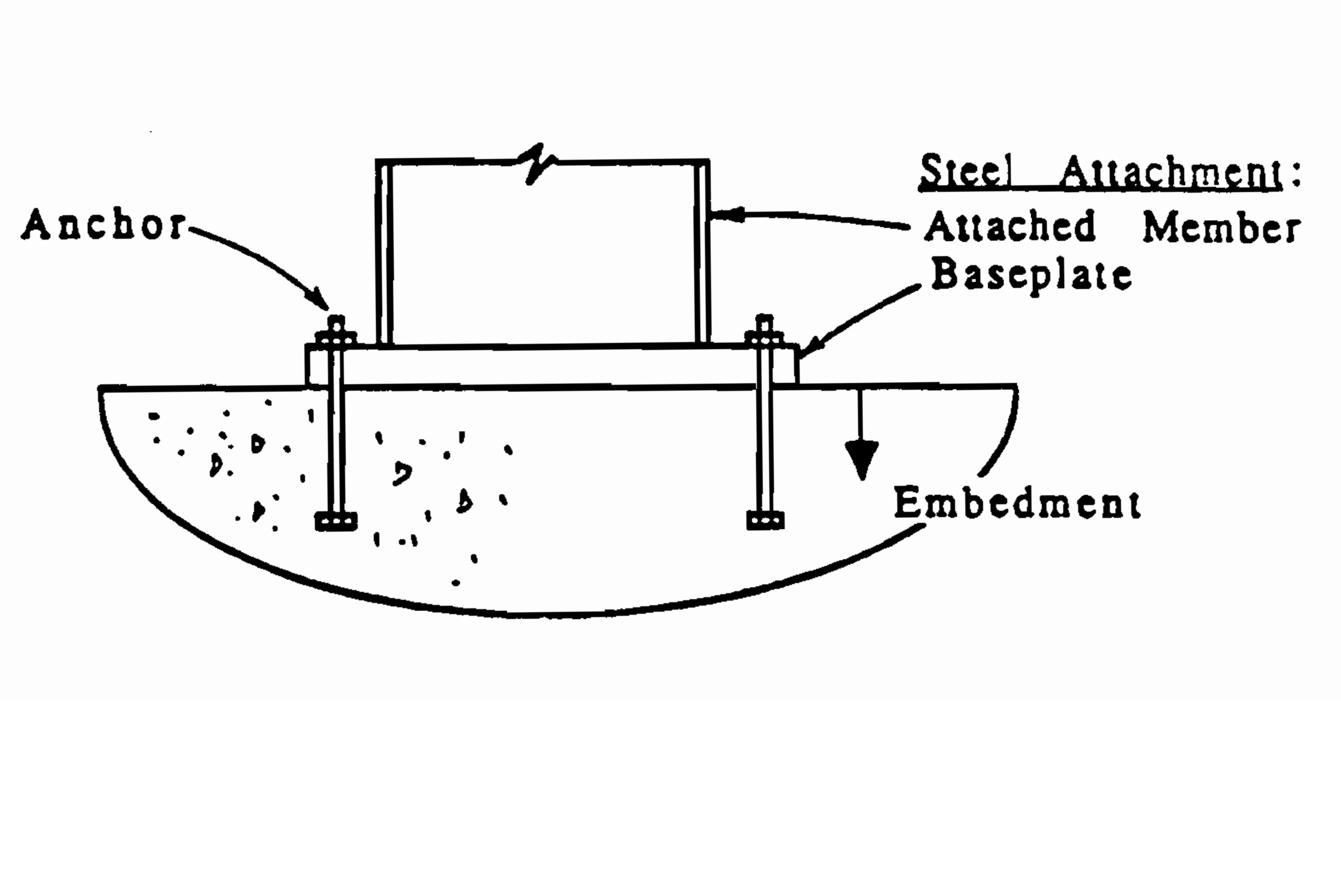
Base plate connection: steel column anchored to concrete foundation — typical fixed support detail.
Reactions generated
Fx, Fy, Fz, Mx, My, Mz
Pinned (Articulated)
Restrains translations only: dx, dy, dz. Rotations are free. The node cannot move but can rotate freely around all axes. This creates a hinge-like connection — no moment is transmitted to the foundation.
When to use
Truss connections (idealized as frictionless pins), column bases with thin base plates or single anchor bolt, braced frame bases, or any joint that allows rotation. Most common support type in steel structures — trusses are almost always pinned.
Reactions generated
Fx, Fy, Fz
Roller
Restrains displacement in a single direction only. The standard Roller Y restrains dy (vertical), allowing the node to slide horizontally. CalcSteel also offers Roller X (dx only) and Roller Z (dz only) for horizontal restraints.
When to use
One end of a simply-supported beam (the other end is pinned), expansion joints in bridges and long structures, sliding connections that allow thermal expansion, or any support that must allow movement in one or more directions to prevent internal stresses from thermal or displacement loads.
Reactions generated
Roller Y → Fy only | Roller X → Fx only | Roller Z → Fz only
Custom
Allows any combination of the 6 DOFs to be independently restrained or released. Use this when none of the standard presets match your connection detail. For example: a support that restrains dx and dy but allows dz (horizontal sliding in one direction).
Available Presets
CalcSteel provides 8 quick-apply presets. Select one or more nodes and click a preset to instantly assign the support:
| Preset | dx | dy | dz | rx | ry | rz |
|---|---|---|---|---|---|---|
| Fixed (ENG) | ● | ● | ● | ● | ● | ● |
| Pinned (ART) | ● | ● | ● | ○ | ○ | ○ |
| Roller Y | ○ | ● | ○ | ○ | ○ | ○ |
| Roller X | ● | ○ | ○ | ○ | ○ | ○ |
| Roller Z | ○ | ○ | ● | ○ | ○ | ○ |
| Fix XY | ● | ● | ○ | ○ | ○ | ○ |
| Fix YZ | ○ | ● | ● | ○ | ○ | ○ |
| Fix XZ | ● | ○ | ● | ○ | ○ | ○ |
Static Stability
For a structure to be stable (not a mechanism), the supports must provide enough reactions to resist all possible movements. The minimum requirements depend on the analysis type:
2D Analysis (plane frame)
Minimum 3 independent reaction components (e.g., one pinned + one roller = 2+1 = 3 reactions). The reactions must not be concurrent (all pass through the same point) or parallel — otherwise the structure can still rotate or translate.
3D Analysis (space frame)
Minimum 6 independent reaction components. A single fixed support provides exactly 6 reactions and is sufficient for stability. Two pinned supports (3+3 = 6) also work, provided they are not aligned along the same axis.
⚠ Common mistake
Placing all supports along the same line (e.g., all nodes on the ground plane with only Roller Y supports) — the structure can still slide horizontally. Always ensure at least one support restrains each global direction (X, Y, Z).
How to Apply Supports in CalcSteel
- 1Select one or more nodes by clicking them or using box selection (drag from left to right).
- 2Open the Support panel from the left toolbar (triangle icon) or from the right-side panel under "Supports".
- 3Click a preset button (Fixed, Pinned, Roller Y, etc.) or toggle individual DOFs in the custom section.
- 4Click "Apply" to assign the support. The 3D canvas will show the support symbol at the node.
Applying a Fixed support to the leftmost node of a truss in CalcSteel.
Tip: You can change a support type by selecting the node and clicking a different preset. Only one support per node is allowed.
References
- Wikipedia — Structural Support — overview of support types in structural engineering
- Wikipedia — Degrees of Freedom (Mechanics) — DOF theory in mechanics
- Wikipedia — Statically Indeterminate Structures — hyperstatic vs. isostatic structures
- Engineering Toolbox — Support Reactions — practical guide with visual examples