LSF (Light Steel Framing)
Studs
The stud carries the roof weight down and, at the same time, holds the wind that hits the wall. This page shows what the engine checks in it by NBR 14762 and where each number appears on screen, in a stud with margin to spare and in one close to the limit.
Overview
The most numerous piece, checked one by one
The Loads page gave the house its dead load, the roof live load and eight wind cases, joined into 26 combinations. The engine uses those combinations to check every bar, and the stud is the most numerous of them.
The example house has 119 pieces of the stud type, all in the same profile: C 89x41/39x12x0.95 in ZAR-230, some of them doubled. It is the stud a new project starts with, roll-formed on the FRAMECAD F325iT; in a stick-built project it is the Ue 90x40x12x0.95, and the checks are the same. The field studs, those of the solid wall, are spaced at 600 mm, 2.80 m tall, with two bracing lines. Each one is checked in every combination, and the worst of them is the one shown on screen.
All of them pass. The most loaded are in Wall 5, in the X strap panel and right next to it, close to the limit: M1012 reaches 0.96. They are the ones that teach how to read the result: what the engine says, where each term comes from, how much is left and what the designer would do if nothing were left.

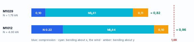
- 0.82: M1029, a Wall 5 stud far from the strap
- 0.96: M1012, next to the strap, among the most loaded in the house
- 2.80 m: stud height, between the tracks
- 0.93 m: between the bracing lines
What it is for
A column that is also a beam
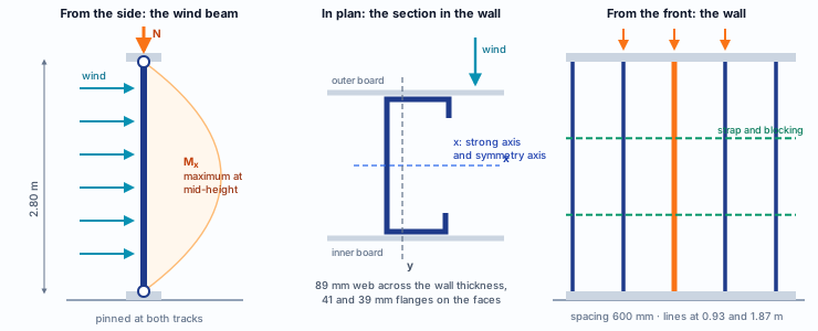
The stud receives the truss on the top track and carries the weight down to the bottom track: it is a column. But it is also the piece the facade board bears on, and the wind that hits the wall reaches it sideways, every 600 mm: it is a beam. Both actions happen together, in the same combination.
| Action | Where it comes from | Axis | In M1012, CB4 |
|---|---|---|---|
| Compression N | The truss resting on the top track, the wall finishes and the steel. | along the piece | 4.00 kN |
| Bending Mx | The wind on the wall, over a 600 mm strip, with the stud simply supported at the tracks: 0.70 kN/m² of suction × 0.60 m = 0.42 kN/m, characteristic value. | x, the strong one | 57.41 kN·cm |
| Bending My | Small, what the analysis of the whole house delivers in the plane of the wall. | y, the weak one | 2.82 kN·cm |
| Shear | The same wind, which reaches the tracks. | in the web | 0.82 kN |
Why the wind weighs so much. Wall 5 is side-on to the wind at 0° and 180°, and there the suction is the largest of all walls: coefficient −0.80 over q = 872 Pa, or −0.70 kN/m² (see Loads). As an order of magnitude, with the characteristic value, the mid-height moment is qL²/8 = 0.42 × 2.80² / 8 = 0.41 kN·m. The combination factors the wind up, and the engine reaches 57.41 kN·cm, the same in every stud of the wall.
What the standard says
Compression: global buckling and effective section
| Where | What it says | In the stud |
|---|---|---|
| NBR 14762, 9.7.2 | The compressive resistance comes from global buckling (flexural, torsional or flexural-torsional) and from the effective area, computed at the stress χ·fy. | Nc,Rd = χ·Aef·fy/γ, with γ = 1.20. |
| 9.7.2.2 | Singly symmetric profile, with x as the axis of symmetry: Ne is the smaller of Ney and Nexz, the flexural-torsional one. | The C is symmetric about x, the strong axis. |
| 9.2 | Effective width: the compressed part of each plate that buckles locally stops counting. | This is local buckling, which gives Aef and Wef. |
| 9.7.3 · Table 11 | Distortional buckling; waived when the edge stiffener is large enough for the web and the flange. | Waived in the compression of the stud. |
| 9.7.4 | Slenderness ratio KL/r of a compression member up to 200. | 78.7 in the stud. |
NBR 14762 · 9.7.2 · the reduction factor.
λ0 = √(A·fy/Ne) χ = 0.658λ0² if λ0 ≤ 1.5 χ = 0.877/λ0² if λ0 > 1.5
λ0 uses the gross area; Aef comes out at the stress σ = χ·fy, and not at fy: a piece that already buckles globally compresses its plates less.
The calculation in M1029, as the report shows it
| Mode | L (cm) | Ne (kN) |
|---|---|---|
| Flexure about x, out of plane | 280 | 56.02 |
| Flexure about y, in plane | 93.33 | 90.35 |
| Torsion | 93.33 | 65.58 |
| Flexural-torsional, x with torsion | 36.81 |
- 1.05: λ0 = √(1.76 × 23 / 36.81)
- 0.63: χ, and σ = 0.63 × 23 = 14.52 kN/cm²
- 1.49 cm²: Aef out of 1.76 of gross area
- 18.04 kN: Nc,Rd = 0.63 × 1.49 × 23 / 1.20
Flexural-torsional buckling governs: it combines the out-of-plane length (2.80 m) with the torsion between the lines (0.93 m). In the effective width, of the 83.3 mm flat part of the web, 55.1 mm count; the flange, held by the stiffener, counts in full. Areas in cm², forces in kN, fy = 23 kN/cm².
Three lengths, and who shortens them
Each global mode has its own length. In an LSF project the app finds them on its own, from the position of the pieces, and sends them to the engine: you type none of them.
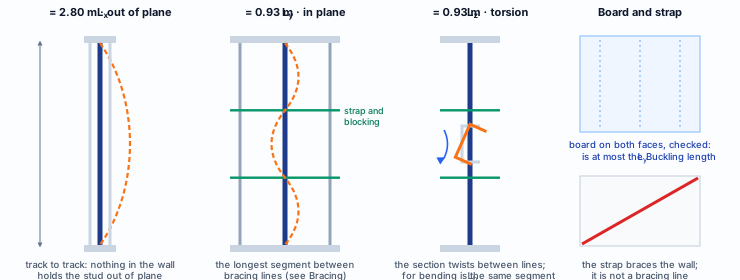
Local, distortional and global: the three ways a thin profile gives way

Local buckling enters through the effective width: Aef in compression, Wef in bending. Distortional buckling is a separate mode, checked by 9.7.3 and 9.8.2.3 when Tables 11 and 14 do not waive it. Global buckling is the χ above. In the stud of the house, distortional buckling is waived in compression, but not in bending, and it is the one that governs bending, as the table below shows.
Bending, and the two actions together
For bending about x, NBR 14762 requires three states to be checked, and the smallest resisting moment applies. All with γ = 1.10. In M1012, with the wind of CB4:
| Where | State | In M1012 | Mn (kN·cm) |
|---|---|---|---|
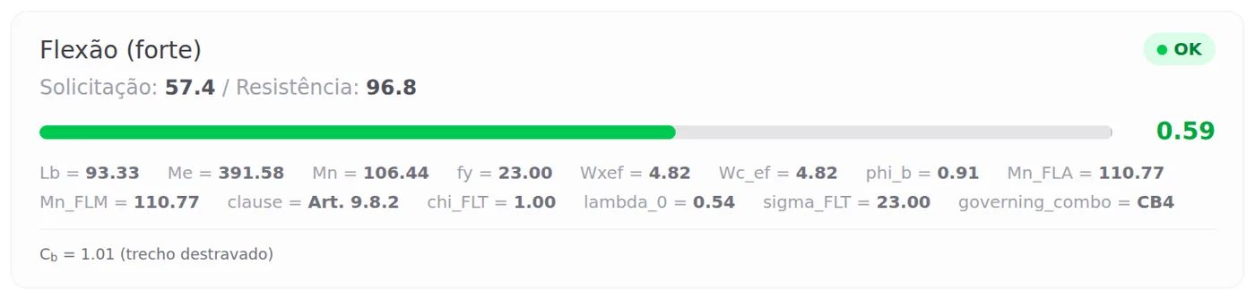
| 9.8.2.1 | Onset of yielding of the effective section: Wef·fy. | Wef = 4.82 cm³ | 110.77 |
| 9.8.2.2 | Lateral-torsional buckling, with Lb and Cb; χFLT = 1 with λ0 up to 0.6. | Lb = 0.93 m, Cb = 1.01, λ0 = 0.54: χFLT = 1 | 110.77 |
| 9.8.2.3 · Tab. 14 | Distortional buckling, with the gross W. | λdist = 0.77, χdist = 0.926 | 106.44 |
- 96.76 kN·cm: Mx,Rd = 106.44 / 1.10: distortional governs
- 0.59: Flexure (strong) alone: 57.41 / 96.76
- 29.67 kN·cm: My,Rd, the weak axis
NBR 14762 · 9.9 · combined bending and compression.
NSd/Nc,Rd + Mx,Sd/Mx,Rd + My,Sd/My,Rd ≤ 1.0
The sum of the three terms, each action divided by its resistance. The moments are those of the piece already deformed: the compression pushes on the bar the wind has bent, and the moment grows.
The deformed piece in the sum
The analysis of the house is first order. To include the effect of compression, the engine divides each moment term by αn = 1 − N/Ne of its axis, with Cm = 1. The report calls this the engine amplification, acréscimo do motor. It also checks, separately, the same sum without αn, the Section yielding (linear) line.
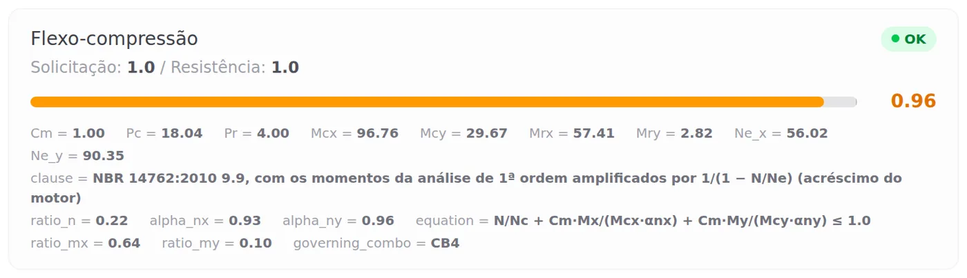
The sum in M1012
4.00/18.04 = 0.22
57.41/(96.76 × 0.929) = 0.64
2.82/(29.67 × 0.956) = 0.10
Flexo-compression = 0.96
αnx = 1 − 4.00/56.02 and αny = 1 − 4.00/90.35. Without the αn, the linear line gives 0.91.
Shear (9.8.3) and moment with shear (9.8.4) are also checked and stay far from the limit in the stud: 0.10 and 0.57 in M1012.
Recommendation
The stud of the house, and what to do if it does not pass
For a single-story house with a 2.80 m ceiling height, the stud a new project starts with already works in almost every wall. What falls to you is checking the wall that takes the most wind and the most roof at the same time.
- 89x41: C 89x41/39x12, 0.95 mm sheet
- 600 mm: stud spacing
- 2: bracing lines in 2.80 m
- ZAR-230: fy = 230 MPa
| Option | Weight of one 2.80 m stud | What it targets |
|---|---|---|
| As is, 0.95 mm | 3.87 kg (1.381 kg/m) | |
| A · 1.15 mm | 4.65 kg, 20% more | Nc,Rd and Mx,Rd go up; the action stays the same. |
| B · double back to back | 7.73 kg, twice as much | Resistances almost double; the wind on the strip is the same. |
| C · 400 mm spacing | 3.87 kg, but more pieces | The wind per stud drops by a third: the characteristic M goes from 0.41 to 0.27 kN·m (hand calculation). |
Decide by the term that weighs. In M1012, the wind accounts for 0.64 of the 0.96. For a difference of a few percent, any of the three options solves it, and the lightest for a few pieces is to change the thickness of just those. A smaller spacing touches the whole wall, and pays off when many pieces exceed the limit.
Step by step
1. Calculate the house
The same Calculate from Loads, on the whole house. On the first calculation of the project, the Verification Colors turn on by themselves: on the LSF tab, the green and red of the result go over the role and wall colors. The button that turns them on and off is in the results column, with a green ✓ and a red ×.
2. Open the view of Wall 5
With the colors on, a click on a piece opens its check, and does not select the wall. To open the view, turn the colors off, select the wall in the plan and click Open view on its card; then turn the colors back on.
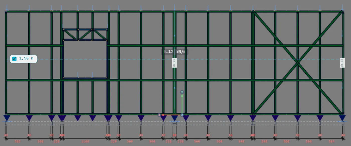
Why on the strap side, and not on the window side. The wind that bends the stud is the same over the whole wall: Mx of 57.41 kN·cm in M1012 and in M1029. The compression is not. The X strap panel is the bracing of the wall: when the wind pushes the house sideways, it takes the force to the ground and the compression gathers near the ends of the strap. M1, at the corner, reaches 9.55 kN with the wind at 0° (CB4); the double stud at the other end, 12.25 kN with the wind at 180° (CB16). The neighbors take a little of that: 4.00 kN in M1012, against 1.79 kN in M1029, far from the strap.
3. Select a stud and read the bar card
With the colors off, select the stud as in Roof: cursor resting on the piece, Tab until the tooltip says Bar, and click. The bar card opens in the corner, with the green line Used in the analysis: the lengths the app sent to the engine for that piece, and why.
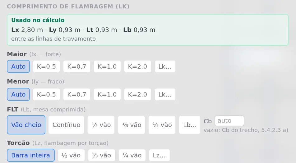
| Symbol | What it is | M1029 |
|---|---|---|
| Lx | Buckling about the strong axis, out of plane: the height of the piece. | 2.80 m |
| Ly | Buckling about the weak axis, in the plane of the wall. | 0.93 m |
| Lt | Torsional buckling (the Lz of the report). | 0.93 m |
| Lb | Unbraced length for lateral-torsional buckling. | 0.93 m |
The bar of the project does not change. The assumption applies only to the calculation; hover over the green strip and the app says so. Changed the bracing or the board? The strip changes with it, even before calculating.
With several studs selected, the strip appears only if all of them use the same lengths.
The reasons the strip can give, in a stud.
"between bracing lines" (the case of the house); "by the mid-height bracing"; "by the sheathing on both faces", when the Buckling length is shorter than the segment between lines; and "no bracing line: full height", when the wall has neither strap nor blocking, and Ly becomes 2.80 m.
4. Turn on the colors and click M1029
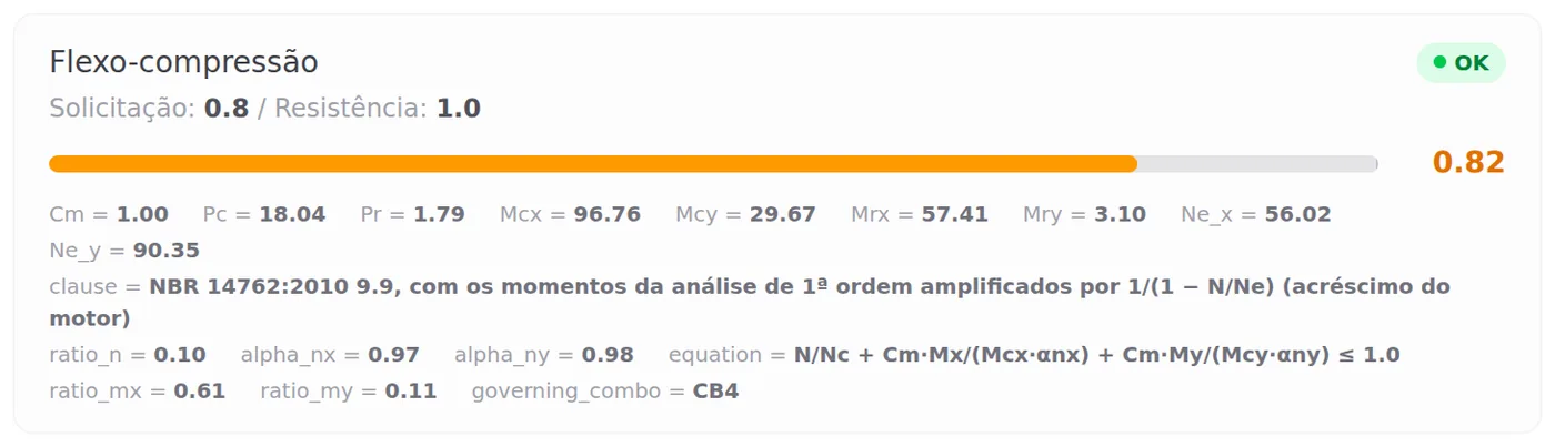
The Bar Diagnostic Report opens. The header gives the profile, the length, the standard, the steel and the governing check; below, one card per check, each with the demand, the resistance and the quantities of the calculation.


| On the card | Means |
|---|---|
| Pr, Pc | Demand N and Nc,Rd, in kN: 1.79 and 18.04. |
| Mrx, Mcx · Mry, Mcy | Demand and resisting moment about each axis, in kN·cm: 57.41 and 96.76; 3.10 and 29.67. |
| Ne_x, Ne_y | The buckling loads that enter the αn of each axis. |
| K_x, K_y, K_z | The length of each mode as a fraction of L: 1.00 · 0.33 · 0.33. |
| phi_c | 1/γ = 1/1.20 = 0.83. |
5. Click a stud next to the strap and compare
Same profile, same height, same wind: M1012 has the same Mx and the same resistances as M1029. What changes is the compression, which goes from 1.79 to 4.00 kN, and enters twice: in the N term and in αn, which increases the moment.

6. Change the profile or double the stud, and calculate again
With the wall view open and a stud selected, the profile card, next to the bar card, changes the profile of that piece (click the profile name at the top of the card, and the search opens) and turns the stud into a double one ("Tornar caixote", to box it, then "Costas", back to back). Calculate again and read the colors and the bar card. The change stays in the project when you save; to test without recording, undo the change before saving.
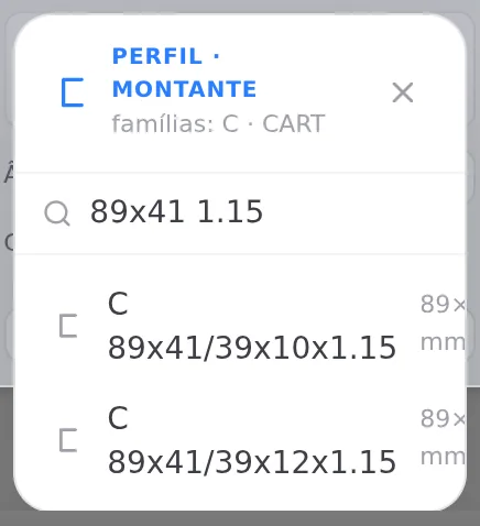
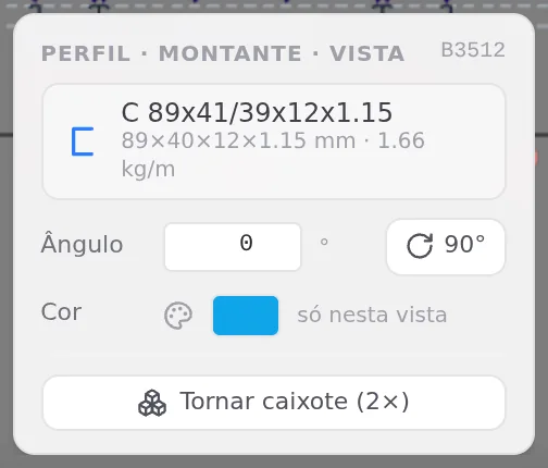
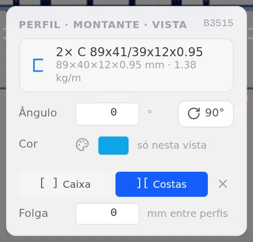
A test, not saved. The house already passes, and the test measures the margin each option buys. The project calculated again, on screen only, with M1, M1012, M1013 and M1014 at 1.15 mm and M1015 and M1016 doubled back to back:
| Stud | Test | Before | In the test |
|---|---|---|---|
| M1012 | 1.15 mm | 0.96 | 0.76 |
| M1013 | 1.15 mm | 0.96 | 0.75 |
| M1014 | 1.15 mm | 0.93 | 0.74 |
| M1 | 1.15 mm, at the corner | 0.97 | 0.78 |
| M1015 | double back to back | 0.96 | 0.51 |
| M1016 | double back to back | 0.95 | 0.50 |
In M1012, the 1.15 mm take Nc,Rd from 18.04 to 22.94 kN and Mx,Rd from 96.76 to 123.2 kN·cm: the same 57.41 kN·cm of wind now weigh 0.50 in the sum, not 0.64. The double stud goes to 41.40 kN and 196.22 kN·cm. In round numbers, the thickness takes 0.20 off the stud, and the double, 0.45. Six pieces changed; the rest of the wall, like M1029 at 0.82, moves less than a hundredth. That is the yardstick for the day a piece goes above 1.00.
Shortcuts
- Ctrl+Enter
Calculate the project
Sends the project to the engine, like the Calculate button.
- AV↵
Wall view
Opens the elevation of the selected wall, seen from outside. Again, goes back.
with one wall selected
- PL↵
Plan view
Goes to plan view. With the wall view open, closes it and keeps the wall selected.
- Home
3D view
Goes to 3D at the last camera pose. With the wall view open, closes it.
Parameters
What comes from the market, and what is yours
The profile, the steel and the spacing come from the market of the project (Market and catalog) and from the wizard (New project wizard); the buckling lengths, from the pieces you drew. The coefficients and assumptions of the engine follow the standard.
| Field | In the house | Who changes it | Effect on the stud |
|---|---|---|---|
| Stud profile | C 89x41/39x12x0.95 | you: wizard or profile card | A, Aef, Wef, inertias: all resistances |
| Steel | ZAR-230 | you, in the wizard | fy in every calculation |
| Spacing | 600 mm | you, in the wall footer | the wind strip of each stud |
| Ceiling height | 2.80 m | you, in the wall | Lx, and Mx with the square of the height |
| Bracing lines | 2, at 0.93 and 1.87 m | you, in Bracing | Ly, Lt and Lb |
| Board on both faces | off | you, in the wizard: Board bracing, exterior and interior | Ly at most the Buckling length; only with both faces |
| Double stud | where the project already has one | you, in the profile card | area and inertias of the piece |
| Loads and wind | Loads | you, in the wizard | N, Mx and My |
| γ for compression · bending | 1.20 · 1.10 | the standard | Nc,Rd and MRd |
| Lx | the height between tracks | the app | pinned at the tracks, about the strong axis |
| Cm · αn | 1.00 · 1 − N/Ne | the engine | the engine amplification in flexo-compression |
The lengths of an LSF stud come from the wall. What changes them is one more bracing line, or board on both faces. The bar card shows the result right away.
Common errors and refusals
When the stud does not come out as you expected
Almost nothing here is a refusal: the stud is always checked. The mistakes are in reading, and the modeling ones show up on the bar card before the calculation.
- The click opens the report instead of selecting. The Verification Colors are on, and a click on the LSF tab opens the check of the piece. To select the wall or a stud, turn the colors off with the ✓× button in the results column.
- "Code applicability limit" with a b/t warning. In the report of every 89x41 stud of 0.95 mm, the Code applicability limit card shows an orange line: flange b/t = 36.1, above 30. It is the recommendation of 9.1.2 (Table 4, note b), to avoid excessive deformation; the maximum the standard accepts is 60. The card stays OK, with ratio 0.00: it is a warning, it does not fail and does not enter the governing ratio.
- "no bracing line: full height". The wall was left without strap and blocking, and Ly, Lt and Lb became 2.80 m. The flexural-torsional buckling load drops and the stud loses a good part of its resistance. Add the lines as in Bracing and check the green strip.
- Board turned on and Ly did not change. The board only enters with both board bracings, exterior and interior, turned on, and only when the Buckling length is shorter than the segment between lines. With lines at 0.93 m, a Buckling length of 500 mm shortens it; one of 1,000 mm does not.
- The Used in the analysis strip disappeared from the card. With several studs selected, of different heights or bracing, the card has no single value to show. Select one stud, or identical studs.
- Slenderness above 200. A compression member with KL/r above 200 fails by 9.7.4. The stud of the house is at 78.7; the limit appears in a tall stud without bracing.
- The strap counted as bracing. The diagonal strap (Straps and blocking) braces the wall in its own plane. It does not cut the Ly of the stud: what cuts it is the strap and blocking line.
- Changing the profile of the whole project for a few studs. Changing the profile in the wizard changes every stud. For a few pieces, change only those, in the profile card, and calculate again.
- Reading only the governing ratio. 0.96 does not say where the number comes from, nor what to do if it rises. The three flexo-compression terms do: if it is the wind, spacing or thickness; if it is the weight, thickness or a double stud.
What the engine checks
From the drawn stud to the color on the wall
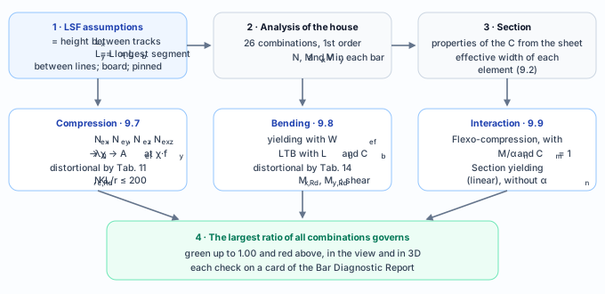
| Step | What happens to the stud |
|---|---|
| LSF assumptions | At calculation time, the app finds the chain of each stud, from track to track, and the strap and blocking lines that cross it. The longest segment becomes Ly, Lt and Lb; the height becomes Lx. The board enters only on both faces. |
| Analysis | The 26 combinations from Loads, on the whole house. The wind on the wall reaches each stud through the spacing strip. |
| Check | Each combination goes through the NBR 14762 checks; the largest ratio of each, and the worst combination, go into the report. |
| Warnings | The Code applicability limit holds the limits of the text. A warning does not govern: it stays on the card with ratio 0. |
The calculation does not touch the project. The LSF assumption enters only what goes to the engine. The bar keeps its usual lengths in the model, and the bar card shows what the calculation used.
What the engine checks in the stud
In each combination, each stud goes through these checks. The largest ratio of all governs and gives the piece its color.
| Check | Clause | In the stud |
|---|---|---|
| Compression | NBR 14762, 9.7.2, 9.2 and 9.7.3 (Table 11) | Global flexural, torsional and flexural-torsional buckling, with the effective area from local buckling; distortional buckling, when Table 11 does not waive it. |
| Slenderness | 9.7.4 | KL/r up to 200. |
| Bending about both axes | 9.8.2 (Table 14) | Yielding of the effective section, lateral-torsional buckling with Lb and Cb, and distortional buckling. |
| Shear and moment with shear | 9.8.3 and 9.8.4 | In the web, with the wind that reaches the tracks. |
| Flexo-compression | 9.9 | The sum of the three terms with the engine amplification (αn), and the linear line, without it. |
| Web crippling | Annex D (Table D.2), γ = 1.35 | At the foot and the head, where the stud bears on the track, with the wind reaction and the bearing length measured on the drawn track. As an order of magnitude, in Wall 5, 0.59 kN characteristic at each end. |
| Deflection | NBR 16970-2, 8.2, Table 3 | h/300 at the middle of the stud, measured relative to its ends, in the serviceability combinations. |
| Lateral displacement | NBR 16970-2, 8.2, Table 3 | The top of the house at H/400 and each story at h/500, on the whole model. |
| Code applicability limit | 9.1.2, Table 4 | Width-to-thickness of each plate: above the recommended value it is a warning, with ratio 0; above the maximum, it fails. |
What stays with the designer
- The connections: the stud to the track and the bottom track to the base (see Connections panel).
- The Buckling length of the board, when board bracing is on: it is an assumption outside the standard, and the backing comes from the manufacturer of the board and its fasteners (see New project wizard).
- The b/t warning above the recommended value: the standard sets it as a recommendation against excessive deformation, and accepting it or not is a design decision.
Shortcuts
- Ctrl+Enter
Calculate the project
Sends the project to the engine, like the Calculate button.
Summary
The path, in one line
Calculate → Verification Colors in the wall view → colors off and Tab to Bar to read Lx, Ly, Lt and Lb on the card → colors on and click the piece for the report → the three flexo-compression terms → test the option and calculate again.
The numbers of the house
- 18.04 kN: Nc,Rd of the 0.95 stud
- 96.76 kN·cm: Mx,Rd, from distortional buckling
- 57.41 kN·cm: Mx from the wind on Wall 5
- 0.96: M1012, next to the strap; no stud above 1.00