Shear Force Diagrams (Vy)
Reading and using the transverse shear diagram in CalcSteel — and when shear, not moment, governs the design
The shear diagram shows the transverse force that each cross-section must transfer. It is the mirror of the moment diagram — its slope — and it peaks exactly where the moment is flat: at the supports. In steel design it is easy to overlook, until a short, heavily loaded span or a notched connection makes it govern.
1. Reading the Shear Diagram
Shear and moment are two views of the same equilibrium. The shear at any section is the slope of the moment diagram, and the applied load is the slope of the shear diagram:
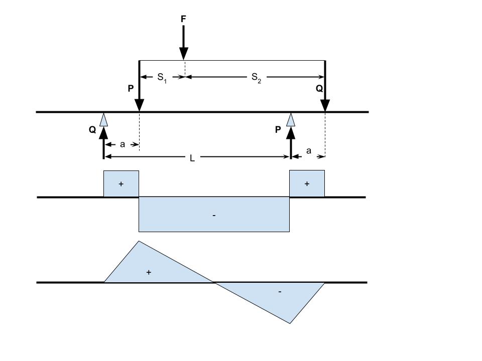
That gives you three instant-reading rules: a point load creates a vertical jump equal to the load; a uniform load creates a straight slope; and wherever the shear crosses zero, the moment is at a local peak. The canonical shapes:
Simply supported + uniform load: linear, ±wL/2 at the supports, zero at mid-span
Central point load: constant blocks of +P/2 and −P/2 with a jump of P under the load
Cantilever + uniform load: triangle growing to wL at the fixed end
2. Vy in CalcSteel — and where Vz lives
In the diagram panel, the Forces button (F) offers Vy — the shear in the local y direction, the one that accompanies strong-axis bending Mz. It is plotted in green, in the strong-axis plane of each bar, evaluated at 21 stations. The weak-axis shear Vz is computed too: it is not drawn as a diagram, but you can read it at any point with the Probe tool (K) and it appears in the bar end forces of the design report.
Reading shear in practice
- F → Vy — activates the shear diagram. Values are in kN (kip in imperial units); the peak of each bar is shown in a dark value pill.
- K — Probe: click along a bar to read the interpolated Vy AND Vz at that exact position — useful near supports and load application points.
- Orig / ENV / CB… — switch between a single case, a combination or the envelope. For connection design, take the ENV shear at the bar end.
- scale slider — visual amplitude only (0.1×–10×). If a diagram looks tiny next to a dominant bar, scale it up — the numbers never change.
Sanity tip: the jump in Vy where a point load sits must equal the applied load, and the end-of-bar shear must match the support reaction. If they do not, look for duplicated loads or an unintended release.
3. When Shear Governs
In an I-section, virtually all the shear is carried by the web — the flanges contribute almost nothing. For stocky webs the design resistance is the plastic shear of the web area; for slender webs, shear buckling cuts the capacity and transverse stiffeners become the economical fix (that is what the vertical plates on bridge girders are doing):
- NBR 8800 — Shear (section 5.4.3) — plastic shear, web slenderness limits and post-buckling strength.
- AISC 360 — Shear (chapter G) — the American treatment, including tension-field action for stiffened webs.
- Connections — the end shear of every beam is what its connection must transfer: bolts in shear, welds, block shear on coped ends.
Situations where shear takes over
- Short spans: with span-to-depth ratios below roughly 10, shear tends to govern before flexure does — typical of transfer beams and heavily loaded corridors.
- Concentrated loads close to a support: the load travels to the support almost entirely as shear, with little moment to show for it.
- Coped or notched beam ends: the reduced section at the connection can fail in block shear well before the mid-span checks matter.
- Slender webs: check the web slenderness before trusting the plastic shear value — if it exceeds the limit, stiffeners or a thicker web are needed.