Deformed Shape (δ)
The elastic curve of the structure — your fastest sanity check and the basis of every serviceability verification
A structure can be strong enough and still fail its users: floors that bounce, roofs that pond, façades that crack against a frame that sways. That is what the deformed shape guards. It is also the first thing to look at after any analysis — if the structure does not deform the way your intuition says it should, no other diagram deserves your trust yet.
1. The Elastic Curve
Deflection is the double integral of curvature, and curvature is moment over stiffness — which is why the deflected shape always mirrors the moment diagram, and why stiffness problems respond to EI, not to fy. Using a stronger steel does not reduce deflections one millimeter; a deeper section does.
Note the L⁴: doubling a span multiplies its deflection by sixteen. Span is the variable that punishes optimism — which is why serviceability limits are written as fractions of L.
Vertical deflection (flecha): the elastic curve of a loaded beam, with δmax at mid-span for uniform load.
Horizontal drift (Δ): frames under wind sway sideways; limits protect partitions, cladding and comfort.
2. The δ Diagram in CalcSteel
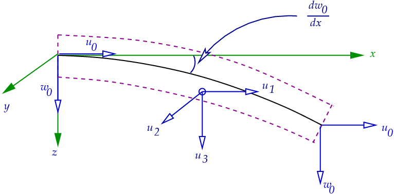
The δ button in the diagram panel draws the true elastic curve of each bar, interpolated with Hermite cubics between the nodes — the bar bends with the shape of its moment, it is not a straight line between two displaced endpoints. Colors and amplitude reflect displacement magnitude.
Reading displacements in practice
- δ — toggles the deformed shape for the active combination. The drawing is exaggerated for visibility; the scale slider (0.1×–10×) tunes the exaggeration without ever changing the numbers.
- K — Probe any point of a bar to read the total displacement in mm (highlighted in red) plus the chord-relative deflection — the local sag measured against the line between the bar ends, which is what the L/350-style limits refer to.
- Orig / ENV / CB… — deflection limits apply to SERVICE combinations. Checking flecha against an ULS combination (loads already factored) overestimates it by the load factors.
The chord-relative reading matters for inclined and rigid-frame bars: a rafter can travel many millimeters with the frame while sagging very little relative to its own chord — and it is the sag, not the ride, that cracks ceilings.
3. Serviceability Limits (ELS)
NBR 8800:2008 (Table C.1) gives the classic reference limits — empirical values that experience shows keep finishes, machinery and people happy. L is the theoretical span, or twice the length of a cantilever:
| Element | Limit |
|---|---|
| Roof purlins (terças) | L/180 |
| Roof beams | L/250 |
| Floor beams | L/350 |
| Beams supporting columns | L/500 |
| Crane runway beams (vertical) | L/600 to L/1000 |
The 2024 revision of NBR 8800 reorganized these limits (Annex C became informative and purlin limits moved to L/250 in Annex B) — check the edition that governs your project. AISC handles the same subject through Design Guide 3 and the L/360 tradition for live-load floor deflection.
- NBR 8800 — Serviceability (ELS) — how CalcSteel runs the deflection checks per service combination.
- AISC 360 — Serviceability (chapter L) — the American treatment: deflection, drift and vibration.
- Bending moment page — the deflected shape is the moment diagram integrated twice; read them together.
Sanity checklist
- Deformed shape first, always: loads pushing the structure the wrong way, a support that slipped, a released bar — all jump out here before any number does.
- Check flecha under service combinations, and against the right limit: L/350 for a floor beam, L/250 for a roof beam — and remember L counts double for cantilevers.
- A beam that passes ULS with room to spare but fails L/350 is asking for depth, not strength: more I, not more fy.
- Persistent excess of a few percent can be absorbed with precamber (contraflecha) for dead load — but never to hide a live-load problem.