Axial Force Diagrams (N)
Tension and compression along the bar axis — the language of trusses, columns and bracing
The axial force diagram shows the force acting along the axis of each bar. CalcSteel follows the universal convention: positive N is tension (the bar is being stretched), negative N is compression (the bar is being squeezed). The distinction is not cosmetic — a tension member is checked against yielding and rupture, while a compression member lives or dies by buckling.
1. Reading the Axial Diagram
In a bar with no intermediate axial loads, N is constant along the length — the diagram is a rectangle. Columns accumulate load floor by floor (and their own weight), so N grows toward the base. In an ideal truss, where members are pinned and loaded only at the nodes, every bar carries pure axial force: that is what makes trusses so efficient.
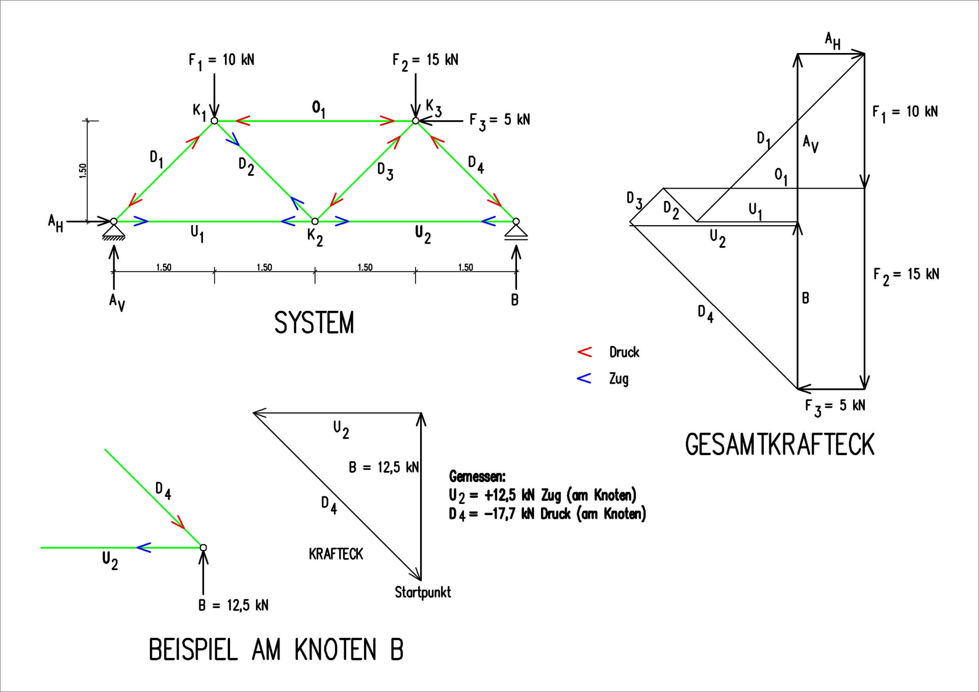
Classic truss under gravity loads: bottom chord and inner diagonals in tension (blue), top chord and end diagonals in compression (red).
Column under a top load P: compression −P at the top, growing to −P−W at the base as self-weight W accumulates.
2. N in CalcSteel — ties included
Activate the N diagram from the Forces button (F) in the diagram panel — it is plotted in blue, with the peak value of each bar in a dark pill, in kN (kip in imperial units). Bars classified as ties (tension-only bracing) get special treatment: for each combination the solver iterates automatically to decide whether the tie is active (in tension) or slack (would be compressed), and slack ties are drawn in light gray.
Reading axial force in practice
- F → N — the axial diagram. Positive = tension, negative = compression; the sign matters more than the magnitude.
- K — Probe: read N at any point of a bar — useful in columns where N varies with height.
- Orig / ENV / CB… — a brace that is in tension under one wind direction is usually in compression under the other. The envelope shows both extremes; the design needs each combination.
- λ — the axial forces from the analysis feed the geometric stiffness of the Linear Buckling Analysis — see the buckling diagram page.
3. From N to the Design Check
The sign of N decides which chapter of the standard applies. Tension members are checked for gross-section yielding and net-section rupture at the connections. Compression members are checked for flexural, torsional and local buckling — and their slenderness is capped by good practice:
- NBR 8800 — Tension (section 5.2) — yielding, rupture and the net-area reduction at bolted ends.
- NBR 8800 — Compression (section 5.3) — the buckling curve, the χ reduction factor and effective lengths.
- AISC 360 — Tension (D) and Compression (E) — the American counterparts of the same checks.
- Combined N + M — real columns carry moment too; the interaction equation ties this page to the bending one.
Sanity checklist
- Sum of column axial forces at the base ≈ total vertical load. If not, something is floating or double-supported.
- Symmetric structure + symmetric load → symmetric N. An asymmetric axial map under symmetric load points to a modeling slip.
- X-bracing modeled as ties: expect one diagonal active and its twin slack (gray) per wind direction — both fully engaged at once means they are not really ties.
- Long compression members with λ near 200 are legal but twitchy — a small extra load or imperfection eats the margin. Consider bracing the mid-length.