Partial Derivatives: Castigliano's Theorem and Steel Truss Deflection
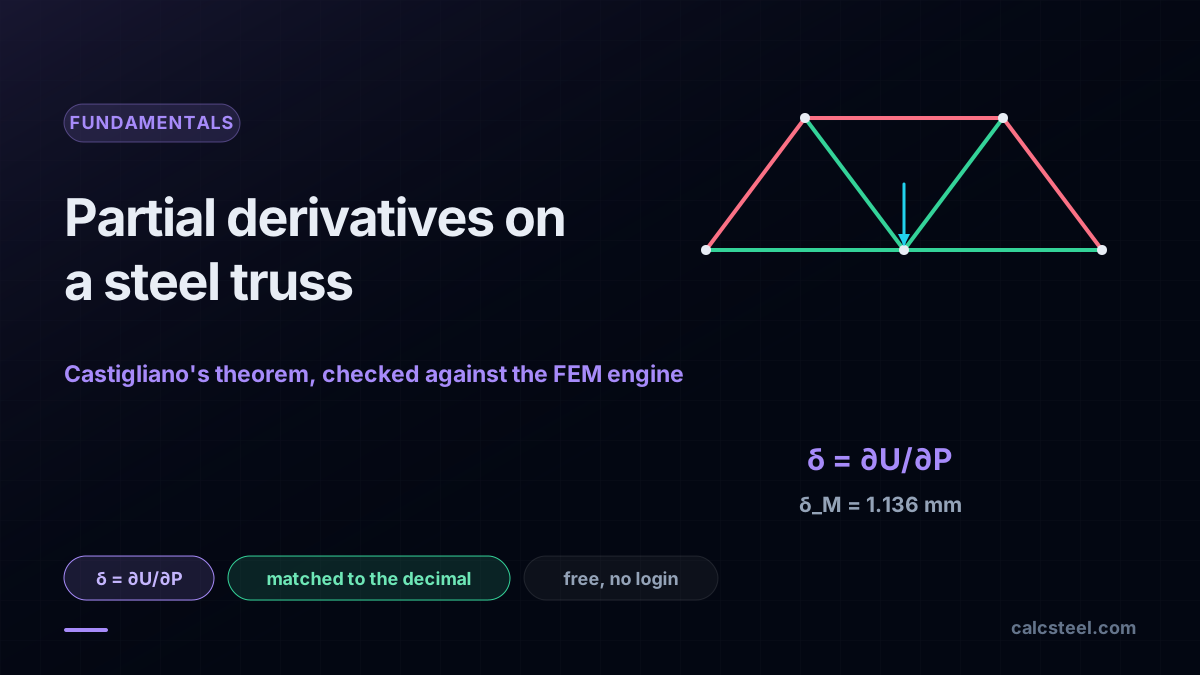
See how partial derivatives power Castigliano's theorem to find steel truss deflection, matched to a real FEM engine to the decimal. Try it free, no login.
Key takeaways
- A deflection is a partial derivative: Castigliano's first theorem gives delta = dU/dP, which becomes delta = sum N (dN/dP) L / EA and gave 1.136 mm under P = 60 kN.
- No load at the point? A fictitious force Q gives the horizontal spread at R of 0.397 mm, with dN/dQ nonzero only on the two bottom chords.
- Indeterminate trusses close with least work: dU/dX = 0 fixed the redundant diagonal at X = minus 9.77 kN and redistributed the forces.
- Every hand result matched the CalcSteel FEM engine to the decimal, the largest force difference being 0.0003 kN.
- This is Calculo I and II on real steel: the ordinary derivative gives shear, the second derivative curvature, the integral areas, and the partial derivative deflection.
The partial derivative has a real job on a steel truss
The partial derivative you met in Calculo II is usually introduced as a tool for surfaces and gradients: how a function of several variables tilts when you nudge one of them. It looks like pure geometry, far from a beam or a bolt. It is not. In 1873 a young Italian railway engineer, Carlo Alberto Castigliano, showed that the same partial derivative computes the deflection of a loaded structure directly, straight off the energy the structure stores.
That is the whole promise of this article. We take one real steel truss, load it, and read three different deflections off partial derivatives of its stored energy. No new physics between them: the same derivative, pointed at three different questions.
- The deflection under the load, where the force actually pushes.
- A deflection where no load acts at all, using a fictitious force that we differentiate and then switch off.
- The internal forces of a statically indeterminate truss, where the derivative set to zero picks the one solution nature actually chooses.
Each answer is matched against the CalcSteel FEM engine to the decimal. That is the point of a real engine behind the words: the hand calculation and the machine solution have to meet, and they do. Everything here runs free in the browser, so you can rebuild the truss yourself while you read.
Three readers will get something different from this. The engineering student gets a concrete reason the partial derivative earns its place in the ementa. The practising calculista gets a clean refresher on energy methods and where they still beat a black box. The self-employed calculista gets a free, browser-native way to check a deflection without buying a seat of anything.
Partial derivatives, the 60-second refresher
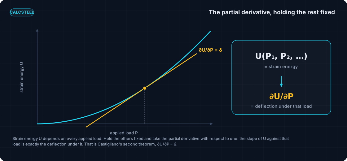
A partial derivative df/dx measures how a multi-variable function f(x, y, z, ...) changes when you nudge one variable and hold all the others fixed. It is the ordinary derivative in every way except one: you decide which variable moves, and you freeze the rest at their current values while you differentiate.
This is exactly the step your calculus sequence builds toward. Calculo I gives you the ordinary derivative of a function of one variable. Calculo II widens the world to functions of several variables, and the partial derivative is the natural first tool there: differentiate with respect to one input at a time. Nothing new is being asked of you, only a choice of which knob to turn.
Here is the pivot that makes the rest of this article work. A loaded structure stores energy, and that stored energy is a function of the loads acting on it: write it U(P1, P2, P3, ...). Change one load and the stored energy changes. So a partial derivative of U with respect to one load, dU/dP1, is precisely the kind of object Calculo II hands you: a multi-variable function differentiated in one of its variables.
Castigliano's insight was to ask what that particular partial derivative means physically. The answer, which the next two sections build carefully, is that it is a deflection. The abstract machinery of Calculo II turns out to be a deflection calculator wearing a disguise.
Strain energy: the function we will differentiate
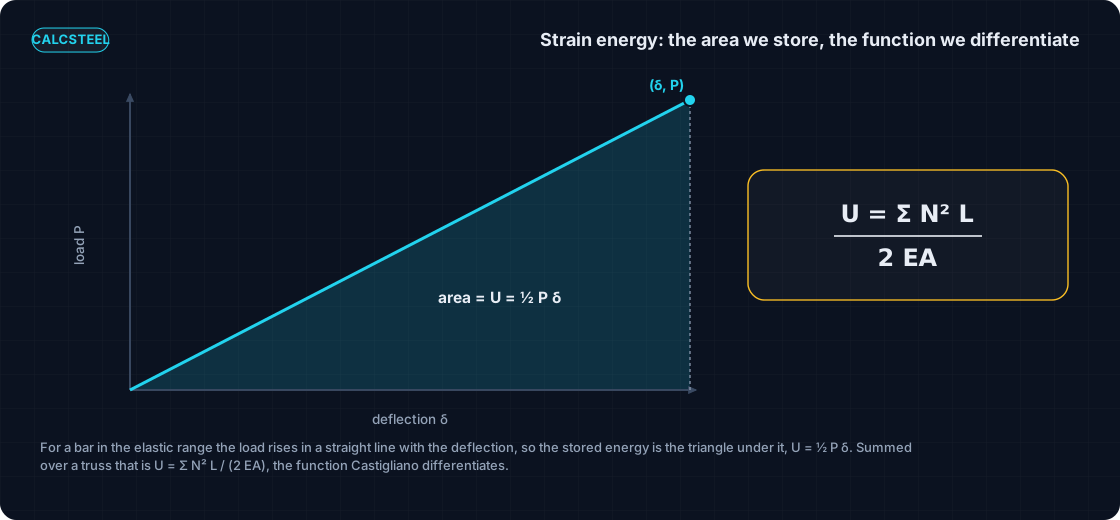
Before we can differentiate the stored energy, we need it as an honest formula. When a structure deforms elastically under load, it stores the work done on it as strain energy, U. In the most general form it is the integral of the energy density over the whole body, U = integral of (1/2) sigma epsilon dV, with sigma the stress and epsilon the strain. That is the quantity a dropped weight has to dump into a structure, which is why it also governs impact loading.
For a single bar carrying only an axial force N, that integral collapses to a compact result:
U = N² L / (2 E A)
where L is the member length, E is Young's modulus and A is the cross-sectional area. A truss is just a set of such bars pinned together, each carrying its own axial force, so its total strain energy is the sum over all members:
U = sum of Ni² Li / (2 E Ai)
Now the sentence that the whole method turns on: U is a function of the loads. It does not look like one, because the loads P do not appear in the formula. They are hiding inside every Ni. In a truss each member force Ni is fixed by the applied loads through equilibrium, so Ni = Ni(P1, P2, ...), and therefore U = U(P1, P2, ...). The energy is exactly the multi-variable function U(P1, P2, ...) from the previous section, written in the language of steel.
That is all we need. We have a function of the loads. Calculo II tells us how to differentiate it in one load at a time. The next section says what that derivative is.
Castigliano's first theorem: deflection = the partial derivative of energy
Here is the theorem, stated plainly. For a linear elastic structure, the displacement at the point of application of a load Pi, measured in the direction of that load, equals the partial derivative of the strain energy with respect to that load:
deltai = dU/dPi
That is the entire idea. The abstract partial derivative of the previous sections is a real, measurable deflection in millimetres.
To turn it into something you can compute, differentiate the truss energy under the sum sign. Starting from U = sum of N² L / (2 E A) and applying the chain rule to each N (which depends on Pi), the factor of 2 cancels and you are left with a working formula:
delta = sum of N (dN/dP) L / (E A)
Read it term by term. For each member you take its force N, multiply by how fast that force changes with the load, dN/dP, multiply by the length L, add up over all members, and divide by the axial stiffness E A. Every quantity on the right is something you already know how to get: N from equilibrium, dN/dP by differentiating that same equilibrium expression, L and E A from the geometry and the section.
The theorem comes with assumptions, and they matter. It holds for linear elastic material, under small displacements, with the loads applied gradually so that all the external work is stored as recoverable strain energy and none is lost to dynamics or yielding. Inside those limits, which cover the vast majority of service-level steel design, the equality is exact.
A word on where this came from. Carlo Alberto Castigliano (1847 to 1884) was an Italian structural and railway engineer who worked for the Northern Italian Railways, the Strade Ferrate dell'Alta Italia. He presented these theorems in his 1873 engineering dissertation at the Politecnico di Torino and published them in 1879 as Theorie de l'equilibre des systemes elastiques. He died at 36. His energy methods sit alongside virtual work, developed by Maxwell in 1864 and by Mohr, as the classical route to deflections that carried structural analysis right up to the arrival of matrix and finite element methods in the 1950s and 1960s.
The recipe, five steps
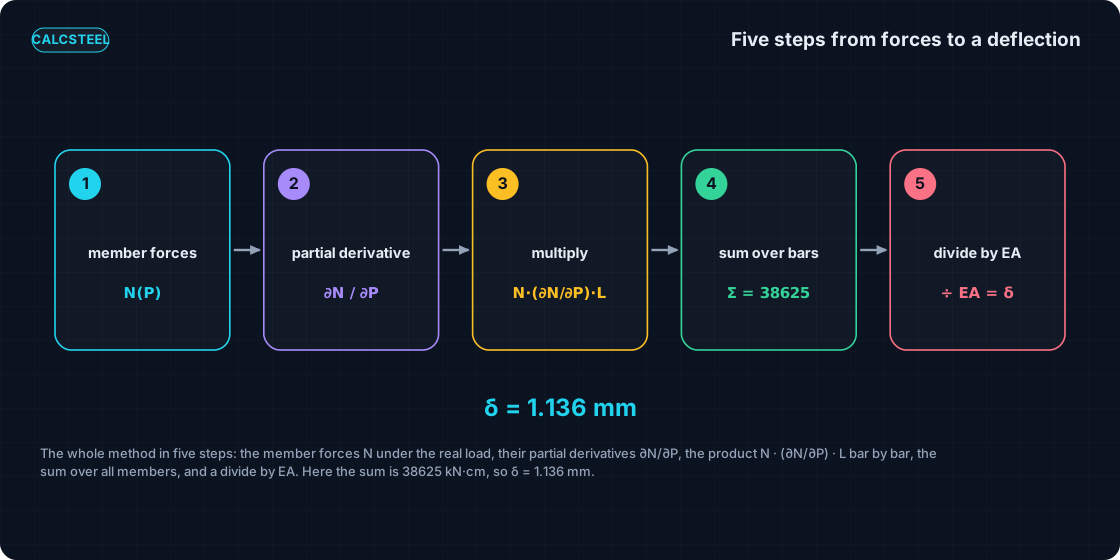
Before we touch a real truss, here is the whole method in one glance. Castigliano's first theorem turns a deflection into a bookkeeping exercise: find the forces, differentiate them, multiply, add, divide. Every worked example in this article is just these five steps repeated.
- Find the member forces N as functions of the load P. Solve the truss for the applied load and keep P as a symbol, so each member force reads as a formula in P rather than a bare number.
- Take the partial derivative dN/dP of each member. Because a truss is linear, this partial derivative is simply the force that member carries per unit of P, holding the geometry and every other load fixed.
- Multiply N times (dN/dP) times L, member by member. This product is each member's own contribution to the deflection, carrying its sign with it.
- Sum over all members. Add the seven contributions into a single number, tension and compression together.
- Divide by EA. The axial stiffness EA converts that force-length sum into a real displacement, in the same length units you used inside the sum.
That is the entire engine. In the next section we run it on a real steel truss and check the answer against the CalcSteel FEM solver to the decimal.
Worked truss 1: the deflection under the load
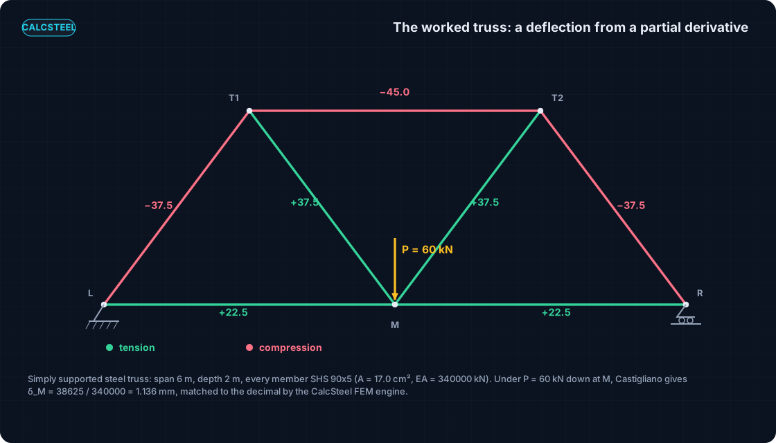
Here is the structure we will carry through the whole article. It is a simply supported steel truss spanning L = 6.0 m with a depth of 2.0 m. The bottom joints are L at (0,0), pinned, M at (3,0), and R at (6,0) on a roller. The two top joints are T1 at (1.5, 2.0) and T2 at (4.5, 2.0). Seven members connect them: the bottom chords LM and MR, the end diagonals LT1 and T2R, the inner diagonals T1M and MT2, and the top chord T1T2.
Every member is the same square hollow section, an SHS 90x5 with area A = 17.0 cm^2 (the value the engine recomputes from the geometry), grade MR250, with E = 200 GPa = 20 000 kN/cm^2. That gives an axial stiffness EA = 340 000 kN for every member. The truss is statically determinate: with m = 7 members, r = 3 reactions, and j = 5 joints, m + r equals 2j, so equilibrium alone fixes all the forces.
Now hang a single point load P = 60 kN downward at the bottom mid-joint M, and ask for the vertical deflection at M, right under the load. That is exactly the situation Castigliano's first theorem was built for: the deflection at the load equals dU/dP, which expands to the sum we assembled in the recipe.
Because the forces are linear in P, step 2 is easy: dN/dP is just the force each member carries per unit of P. So we solve the truss once for P = 60 kN, read the seven member forces (positive in tension, negative in compression), and the per-unit column follows by dividing by 60. The last column is the product N times (dN/dP) times L that we sum, with lengths written in centimetres so the answer lands in centimetres.
| Member | N (kN) | dN/dP | L (m) | N (dN/dP) L (kN.cm) |
|---|---|---|---|---|
| LM | +22.5 | +0.375 | 3.0 | +2 531.25 |
| MR | +22.5 | +0.375 | 3.0 | +2 531.25 |
| LT1 | -37.5 | -0.625 | 2.5 | +5 859.375 |
| T2R | -37.5 | -0.625 | 2.5 | +5 859.375 |
| T1M | +37.5 | +0.625 | 2.5 | +5 859.375 |
| MT2 | +37.5 | +0.625 | 2.5 | +5 859.375 |
| T1T2 | -45.0 | -0.750 | 3.0 | +10 125.0 |
| Sum | +38 625 |
Notice that every product in the last column is positive, even for the compression members LT1, T2R, and T1T2. A compression member has a negative N and a negative dN/dP, and the two minus signs multiply to a plus. This is the physical heart of the method: compression members store energy and contribute to the deflection exactly as much as tension members do.
The sum is 38 625 kN.cm. Divide by EA = 340 000 kN and you get the deflection:
delta_M = 38 625 / 340 000 = 0.1136 cm = 1.136 mm downward.
Now the punchline. We built this same truss in the shipping CalcSteel FEM engine, the same one that runs inside the browser app, and asked it for the vertical displacement at joint M. It returns 1.136 mm, the same to the decimal. A partial derivative you learned to take in Calculo II, applied to the stored energy of a steel structure, lands on the identical number a full finite-element solver computes. (If you prefer the energy form, the same seven members give sum N^2 L = 2 317 500 kN^2.cm, and delta = sum N^2 L / (P.EA) returns 1.136 mm as well.)
A deflection where there is no load: the fictitious force
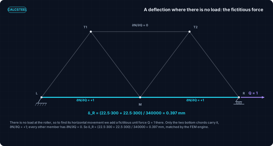
Castigliano's first theorem gives you the deflection at a load, in the direction of that load. So what do you do when you want the movement at a point where nothing is pushing? On our truss, the load at M is vertical, yet a designer often cares about the horizontal spread at the roller R, where there is no horizontal force at all. There is a clean trick for exactly this case.
Add a fictitious force Q at R, pointing in the direction you want to measure, here horizontally. Now every member force is a linear combination of the real load and the fictitious one, N = a P + b Q. Take the partial derivative with respect to Q, then set Q = 0 at the very end. The real load stays; the imaginary one vanishes after it has done its job of picking out the right displacement.
The beauty is in what the derivative turns out to be. Since N = a P + b Q, we have dN/dQ = b, which is precisely the member force under a unit horizontal load at R. So step 2 of the recipe becomes: solve the truss for a single unit force at R, in the direction of interest, and read off the member forces. Those are your dN/dQ values, and setting Q = 0 means the real member forces N in the sum are just the ones from Worked truss 1.
A unit horizontal load applied at the roller R runs straight along the bottom chord to the pin at L, and reaches no other member. So only the two bottom chords have a non-zero dN/dQ:
- LM: dN/dQ = +1.0
- MR: dN/dQ = +1.0
- every other member: dN/dQ = 0
The sum collapses to two terms. Using the real bottom-chord forces N_LM = N_MR = +22.5 kN and lengths of 300 cm each:
delta_R,horizontal = (22.5 x 1 x 300 + 22.5 x 1 x 300) / 340 000 = 13 500 / 340 000 = 0.03971 cm = 0.397 mm.
We asked the CalcSteel FEM engine for the horizontal displacement at R on the same model. It returns 0.397 mm, the same to the decimal, a deflection read cleanly at a point that carried no real horizontal load.
If that unit-load step feels familiar, it should. The quantity dN/dQ, the member force under a unit dummy load at the point and direction of interest, is the dummy-load force of the virtual-work (unit-load) method. That is why Castigliano and virtual work always produce the identical sum, member by member: they are writing down the same product N times (unit-load force) times L over EA. The difference is only the road each one travels to get there. Virtual work starts from an equilibrium argument with a dummy load; Castigliano reaches the very same result from the stored energy and a single partial derivative. Two branches of the Calculo II toolkit, one steel deflection.
Try it: deflection, live
You just watched a partial derivative turn into a deflection twice on paper. Now do it yourself, without picking up a pencil. The interactive calculator embedded right here lets you set a load and read the deflection back, so the abstract dU/dP becomes a number you can push around.
Change the load, change the geometry, and watch the deflection respond. This is the same idea as our worked truss: energy stored in the members, differentiated with respect to the load, read out as a displacement. Seeing it move is the fastest way to trust the method.
It is genuinely free, there is no login for the math, and there is no limit on how many times you run it. Explore it the way you would explore a graph in Calculo II: nudge one thing, hold the rest fixed, and read the change.
Max moment
45 kN·m
Max shear
30 kN
Max deflection
10.55 mm
= L/569
Bending stress σ
84.4 MPa
σ = M/Sx
Utilization
44.0%
NBR 8800 · δ ≤ L/250
Geometry & supports
Section
Ix 7999 cm⁴ · Sx 533 cm³ · 42.2 kg/m
Point loads (↓ positive)
None — add as many as you need.
Distributed loads (uniform or trapezoidal)
Model sketch
Diagrams — free PNG / SVG / CSV export, no watermark
Step-by-step — the calculation memory of YOUR beam
IPE 300 · L = 6 m · fy = 250 MPa
1. Reactions (equilibrium of the solved FEM model)
ΣFy = 0 · ΣM = 0
R_A = 30 kN · R_B = 30 kN
2. Peak shear (read from the SFD)
Vmax = |V(x)|max
Vmax = -30 kN @ x = 6 m
3. Peak moment (read from the BMD)
Mmax = |M(x)|max
Mmax = 45 kN·m @ x = 3 m
4. Peak deflection
EI = 15998 kN·m² (E = 200 GPa)
δmax = 10.55 mm @ x = 3 m = L/569
5. Elastic bending stress
σ = Mmax / Sx = 45.00 × 10³ / 533.3
σ = 84.4 MPa
6. Bending check — both codes, side by side
NBR 8800: σ ≤ fy/1.10 = 227.3 MPa · AISC 360: σ ≤ 0.90·fy = 225 MPa
NBR 37.1% PASS · AISC 37.5% PASS
7. Deflection check (serviceability — code-independent)
δ ≤ L/250 = 24 mm
10.55 mm / 24 mm = 44.0% PASS
Recomputed live from the current inputs by the direct-stiffness FEM engine — change any load and every step updates. Reproduce it by hand with the formulas in the sections below.
Lightest catalog profiles that pass (974 flexural candidates · NBR 8800)
| Profile | Std | Weight | Total steel | σ util | δ util | |
|---|---|---|---|---|---|---|
| W310x21 | AISC | 21 kg/m | 126 kg | 83% | 98% | |
| VS 300x23 | BR | 22.6 kg/m | 136 kg | 71% | 84% | |
| U 300x90x6.3 | BR | 23.1 kg/m | 139 kg | 82% | 98% | |
| U 300x100x6.3 | BR | 24.1 kg/m | 145 kg | 77% | 91% | |
| VS 250x25 | BR | 24.6 kg/m | 148 kg | 70% | 100% |
Elastic bending (σ = M/Sx vs fy/γa1, γa1 = 1.10 — NBR 8800) + deflection screening of the full flexural catalog. Lateral-torsional buckling, shear and local buckling are NOT checked here — run the full NBR 8800 / AISC 360 verification in the 3D editor.
Castigliano's second theorem: least work for the indeterminate truss
Everything so far assumed a truss you can solve with equilibrium alone. Our shared truss is statically determinate: seven members, three reactions, five joints, so m plus r equals 2j exactly. The joint equations are enough, and Castigliano's first theorem reads the deflection off the top.
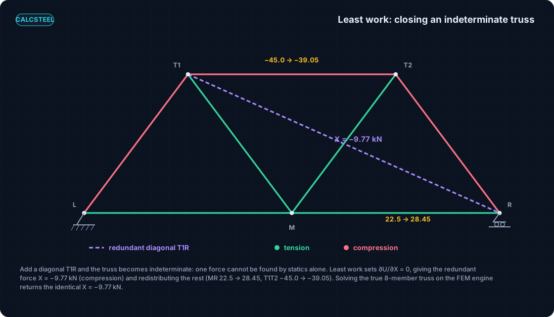
Add one more diagonal and that balance breaks. Put a member T1R across the truss (length 4.924 m) and now you have eight members and three reactions against five joints, so m plus r equals 2j plus 1. There is one more unknown force than equilibrium can pin down. The structure is once indeterminate, and the joint equations run out one equation short.
Castigliano's second theorem, the theorem of least work, closes exactly that gap. It says the redundant force takes the value that minimises the strain energy: dU/dX = 0. The structure, left to itself, settles into the least-energy state, and that condition supplies the missing equation.
Differentiating the energy with respect to the redundant force X and setting it to zero gives a compact formula:
X = minus sum(N0 n L) / sum(n squared L)
Here N0 are the member forces in the released determinate truss under the real 60 kN load (exactly the SIM-1 forces), and n are the member forces under a unit tension in the redundant diagonal alone. It is the same energy, the same partial derivative, now solved for a force instead of a displacement.
For our truss the result is X = minus 9.77 kN. The sign matters: the added diagonal goes into compression. Once you know X, the rest of the members redistribute, because each one now carries its old N0 plus its share n times X.
| Member | N0 released (kN) | N indeterminate (kN) |
|---|---|---|
| LM | +22.5 | +22.5 |
| MR | +22.5 | +28.45 |
| LT1 | -37.5 | -37.5 |
| T2R | -37.5 | -32.54 |
| T1M | +37.5 | +42.46 |
| MT2 | +37.5 | +32.54 |
| T1T2 | -45.0 | -39.05 |
| T1R (redundant) | 0 | -9.77 |
Read the redistribution physically. The bottom chord MR rises from +22.5 to +28.45 kN and the top chord T1T2 eases from minus 45.0 to minus 39.05 kN. The inner diagonal T1M climbs from +37.5 to +42.46 kN while MT2 relaxes from +37.5 to +32.54 kN, and the end diagonal T2R eases from minus 37.5 to minus 32.54 kN. LM and LT1 do not move. The new member simply takes some load off one path and hands it to another, which is what a redundant member is for.
Then the check that matters. We built the true eight-member indeterminate truss in the shipping CalcSteel FEM engine and solved it directly, no least-work formula involved. It returns X = minus 9.77 kN and every redistributed force above, matched to the decimal (the largest difference across all members is 0.0003 kN). A partial derivative set to zero and a full stiffness solve land on the same numbers.
A note on the history. The principle of least work was first stated by Luigi Federico Menabrea in 1858. It was Castigliano who gave it a rigorous, general proof, which is why the least-work theorem is often called the Menabrea-Castigliano theorem. If you want to see the same redistribution from the member-force side, our steel truss design post walks the forces themselves.
Where this sits in the calculus-to-structures map
Step back and the whole arc from Calculo I and II lands on real steel, one tool at a time. The ordinary derivative gives the rate of change along a beam: dM/dx equals the shear force. Differentiate once more and the second derivative becomes the curvature of the elastic line.
Run the derivative backward and the definite integral recovers a quantity as the area under a diagram. And now the partial derivative, the object you met for surfaces and gradients, gives a deflection straight from the stored energy: delta = dU/dP.
It is one coherent calculus, not four disconnected tricks. Same idea of a rate of change, applied to different functions of a structure, each one producing a number an engineer actually checks. The partial derivative is simply the last member of that family, and it is the one that reads a displacement.
From a deflection to the code check
A deflection is only half of an engineering answer. The other half is the comparison a code makes: is that movement small enough for the structure to serve its purpose? Castigliano gives you the number, and serviceability tells you what the number is allowed to be.
Take the deflection we computed under the load. The partial derivative of the strain energy gave delta_M = 1.136 mm at the loaded joint, and the CalcSteel FEM engine agreed to the decimal. Now put that against the span. The truss spans 6.0 m, which is 6000 mm, so the deflection is a ratio of 6000 / 1.136, that is L/5282.
Serviceability limits are written exactly in this L over delta form. A common service limit for this kind of member is L/360, which on a 6.0 m span would allow 6000 / 360 = 16.7 mm of deflection. Our 1.136 mm sits far inside that envelope: L/5282 is roughly fifteen times stiffer than the L/360 line demands.
So the truss is deflection-comfortable, and it is worth being clear about why we are showing it. The point here is the method, not a dramatic failing check. Castigliano produces the delta; the code takes that same delta, forms the L/delta ratio under service load, and passes or fails it. The partial derivative you learned in Calculo II feeds straight into the serviceability clause an engineer signs.
If you want to see where those limits come from and how the ratios are chosen, read the deflection-limits guide, and for the beam-side view of a deflection as the peak of an elastic curve, see maximum beam deflection.
Common mistakes and FAQ
The formula is short, which is exactly why the errors are easy to make. Here is the checklist that keeps a Castigliano deflection honest.
- dN/dP is a partial derivative. When you differentiate, hold the geometry and every other load fixed. You are nudging one load and watching one response, nothing else moves.
- To read a deflection you need a load there. Real or fictitious, there must be a load at the exact point and in the exact direction you want the movement. No load at that spot, no partial derivative to take.
- Keep the sign of every N. The sum uses N times dN/dP, and a compression member (negative N) with a negative dN/dP contributes a positive product just like a tension member. Compression members pull their full weight in the deflection; dropping their sign quietly throws the answer off.
- Keep units consistent. Length L and area A must live in the same system. In the worked truss we carried L in cm inside the sum so that dividing by EA in kN and cm gave a clean centimetre of deflection.
- It assumes linear-elastic, small-displacement behaviour. Loads applied gradually, no yielding, no large geometry change. Outside that box the strain-energy expression itself is no longer the function you differentiated.
- The result is the displacement in the direction of the load. A vertical load gives a vertical deflection; a horizontal fictitious force gives a horizontal one. It is not automatically the vertical movement unless the load was vertical.
What is the difference between a partial derivative and an ordinary derivative here? An ordinary derivative like dM/dx tracks one function of one variable, as in dM/dx equals the shear force. Strain energy U depends on several loads at once, U(P1, P2, ...), so dU/dP is a partial derivative: you change one load and freeze the rest. That is precisely the object Calculo II introduces for functions of several variables.
Why do Castigliano and virtual work give the same answer? Because dN/dQ, the partial derivative of a member force with respect to a fictitious unit load, is identical to the unit-load member force of the virtual-work method. The two techniques build the same sum from two different starting points, energy versus virtual work. See the unit-load method for the parallel route.
Can I use Castigliano on an indeterminate structure? Yes. That is what the second theorem, the theorem of least work, is for. The redundant force takes the value that minimises strain energy, dU/dX = 0, and the member forces redistribute accordingly. In the worked example the redundant diagonal settled at X = minus 9.77 kN, matched by the FEM engine to the decimal.
Does the section size change the deflection? Yes, through EA. A member force N depends on the load and the geometry, but the deflection divides by EA, so a larger area A or a stiffer material E gives a smaller deflection for the same forces. The truss forces in our example do not care about A because the truss is determinate, but the movement does.
Key takeaways
One truss, three deflections, all read straight off partial derivatives of the stored energy, and all matched to a real FEM engine to the decimal.
- A deflection is a partial derivative. Castigliano's first theorem says the displacement at a load equals dU/dP, which becomes the working sum delta = sum of N (dN/dP) L / EA. On the worked truss that gave delta_M = 1.136 mm under P = 60 kN.
- No load at the point? Add a fictitious one. The horizontal spread at the roller came out at 0.397 mm because dN/dQ picked out only the two bottom chords, and that dN/dQ is exactly the unit-load member force of virtual work.
- Indeterminate structures close with least work. Castigliano's second theorem sets dU/dX = 0, which fixed the redundant diagonal at X = minus 9.77 kN and redistributed the forces, again matching the engine.
- The number feeds the code. That 1.136 mm over 6.0 m is L/5282, comfortably inside an L/360 service limit of 16.7 mm. The partial derivative lands on a real serviceability check.
- This is Calculo I and II doing structural work. The ordinary derivative gives shear, the second derivative gives curvature, the integral gives areas under diagrams, and the partial derivative gives deflection. One arc, all landing on real steel.
Now put your hands on it. Build the truss, load it, and read the deflection yourself in o CalcSteel, a browser-native structural steel design and analysis tool with a genuine FEM engine. The math and the calculators are free, no login, unlimited, and if you are a student the /education offer is free for you. The proof is not a countdown trial; it is a tool you can open right now and check against every number on this page.
Sources
- 1.Castigliano, Theorie de l'equilibre des systemes elastiques et ses applications (1879), the original theorems
- 2.Gere and Goodno, Mechanics of Materials (strain energy, Castigliano's theorem, unit-load method)
- 3.Hibbeler, Structural Analysis (energy methods, truss deflections, the method of least work)
- 4.Timoshenko and Young, Theory of Structures (classical energy methods, Menabrea and Castigliano)
- 5.Eurocode EN 1993-1-1, Design of steel structures: General rules (serviceability deflection limits)
Try CalcSteel for free
Model, analyze and design steel structures in your browser. No install, no signup.
Open the 3D editor