Deflection Limits in Steel Design Codes

A steel beam can pass every strength check and still be a failure in the eyes of its occupants: bouncy floors, cracked plaster, doors that jam, ponding water on a flat roof. That is the job of deflection limits, the serviceability rules that cap how much a member may sag under service loads. This article traces where the famous L/360 came from, what NBR 8800, AISC 360, Eurocode 3 and IS 800 actually require, and how design software turns the check into a one-line verdict.
Key takeaways
- Deflection is a serviceability limit state (SLS): checked under unfactored service loads, separate from the strength (ULS) check.
- The span-proportional idea (limit = L/n) dates to Thomas Tredgold around 1820 at L/480; 19th-century American practice relaxed it toward L/360 to control plaster cracking.
- Numerical limits live in different places per code: IBC Table 1604.3 (US), the National Annex for Eurocode 3, Table 6 of IS 800, and Annex C of NBR 8800 (informative since the 2024 revision).
- Software computes the elastic deflection from the same finite-element model used for strength, then compares it to the code ratio for each load case.
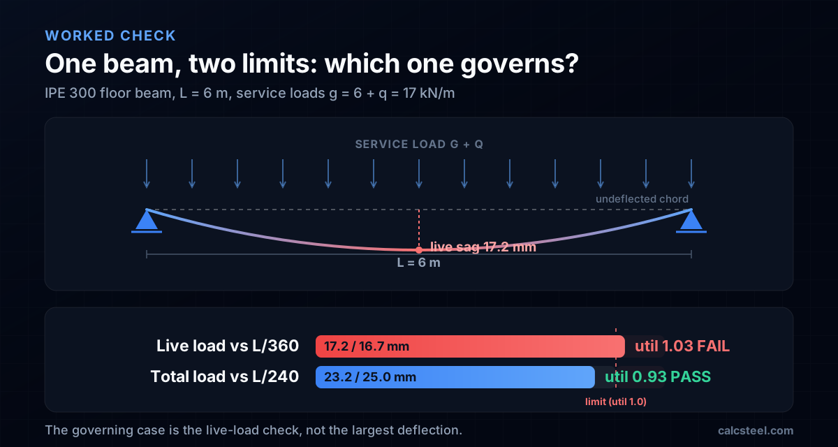
- In a worked IPE 300 floor beam (6 m span, service loads g = 6 and q = 17 kN/m) the live-load L/360 check fails at utilisation 1.03 while the total-load L/240 check passes at 0.93: the governing case is not always the largest deflection, and camber, which only offsets dead-load sag, cannot rescue it.
Why deflection is its own check
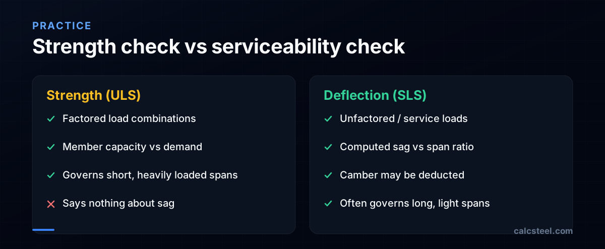
Structural codes split verification into two worlds. The ultimate limit state (ULS) asks whether a member will break: it uses factored load combinations and compares demand to capacity. The serviceability limit state (SLS) asks whether the structure is comfortable and durable to use: it works with unfactored, real-life service loads and checks things like vibration, cracking and, above all, deflection.
A member can be perfectly safe and still unserviceable. A long, lightly loaded floor beam may use only a fraction of its bending capacity yet sag enough to crack a plaster ceiling, make a floor feel springy, or pull a partition out of plumb. On flat roofs, excessive sag can let water pond, which adds load, which adds sag, which adds water, a feedback loop that codes explicitly try to prevent.
Because the two checks answer different questions, they use different loads and can be governed by completely different members, which is exactly why deflection deserves a dedicated workflow.
Where L/360 actually came from
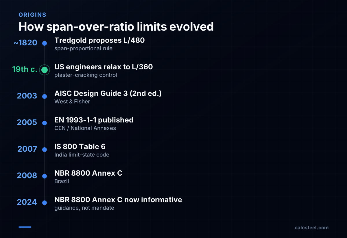
The idea of capping deflection as a fraction of span is older than steel design itself. It is widely traced to Thomas Tredgold, an English engineer who published criteria for the design of flexural members in his Elementary Principles of Carpentry around 1820. Tredgold's recommendation, expressed as roughly 1/40 inch of sag per foot of span, works out to about L/480, a fairly strict ratio, and was aimed squarely at protecting plastered ceilings below timber floors from cracking.
Later in the 19th century, American practice relaxed the allowable deflection toward L/360, the value that still anchors floor-beam practice today. The number is usually explained as a plaster-cracking control: it worked reasonably well at limiting (not eliminating) cracks in the brittle lath-and-plaster finishes common at the time. Engineering literature is candid that L/360 is adequate for normal cases but only just, and that part of its historical success came from buildings rarely seeing their full design load and from load-sharing among members.
The lesson is that these ratios are calibrated rules of thumb, not derived constants, which is why every modern code lets engineers tighten them for sensitive finishes.
What each code requires
One of the most confusing things for new engineers is that the major steel codes do not all print the limits in the same place, or even mandate them at all.
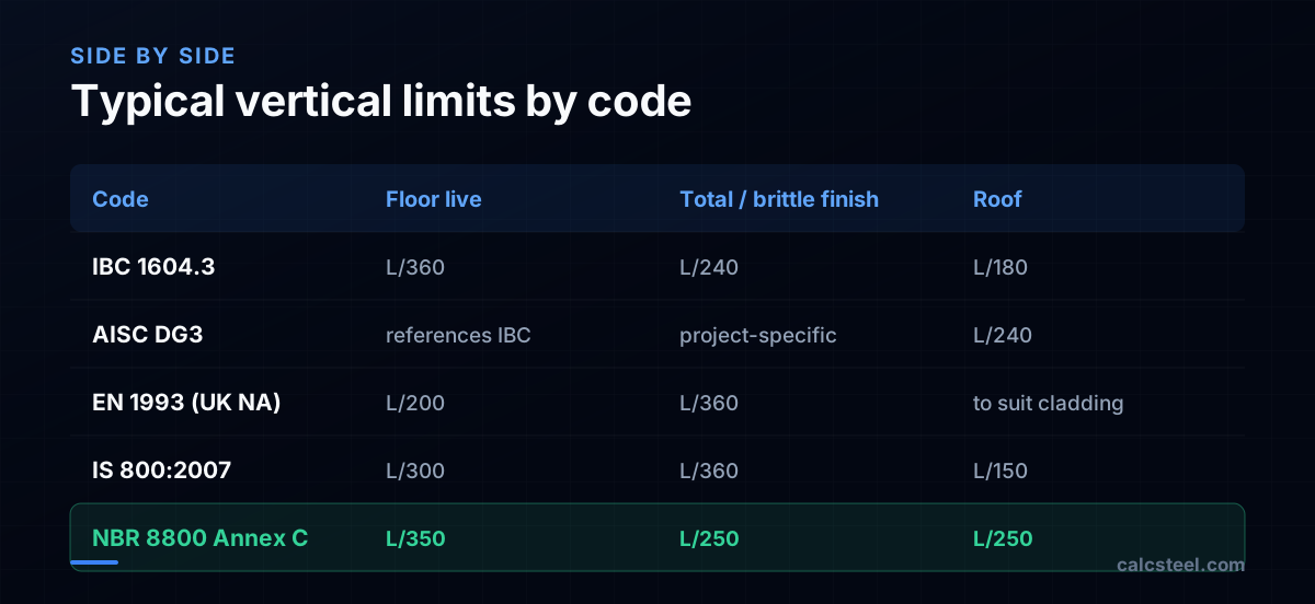
- United States (AISC 360 / IBC): The AISC Specification treats deflection as a serviceability matter and does not tabulate limits; it points to the governing building code. IBC Table 1604.3 gives the practical numbers, commonly L/360 for floor live load, L/240 for floor total load, and L/180 for roof members. AISC's Design Guide 3, 2nd edition (2003), by West and Fisher, is the deeper reference.
- Europe (Eurocode 3, EN 1993-1-1:2005): Clauses 7.2.1 and 7.2.2 set the philosophy but deliberately leave the numbers to each country's National Annex as Nationally Determined Parameters. The UK NA, for example, gives suggested values such as L/360 for beams with brittle finishes and L/200 for other beams, verified under variable actions only.
- India (IS 800:2007): Table 6 lists limits by element and finish, e.g. span/300 for typical members not susceptible to cracking and span/360 where elements are susceptible to cracking.
- Brazil (NBR 8800): Annex C (Table C.1) gives recommended vertical and horizontal limits, including L/350 for beams supporting finishes subject to cracking, and notably became informative rather than normative in the 2024 revision.
Reading the ratios in millimetres
The notation L/n is simply the span divided by a number: the larger the denominator, the stricter the limit and the less sag allowed. For a concrete feel, take a 6 m (6000 mm) simply supported beam:
- L/180 (typical roof) allows about 33 mm of sag.
- L/240 (floor total load) allows 25 mm.
- L/360 (floor live load) allows about 17 mm.
- L/480 (Tredgold's original) would allow only 12.5 mm.
Two subtleties matter. First, codes apply different limits to different load cases: live load alone is often held tighter than dead-plus-live, because permanent sag can be cambered out. Second, camber (a deliberate upward fabrication curve) may be deducted from the computed dead-load deflection in several codes, including NBR 8800, up to the deflection caused by permanent actions. That can be the difference between pass and fail on long spans. You can check any span against these ratios in seconds with the free beam deflection calculator, no sign-up required.
How software automates the check
Deflection is, mathematically, the easy part. The same finite-element model a tool builds to find member forces also yields nodal displacements: the solver assembles the global stiffness matrix, applies the service-load vector, and solves for the displacement field. The transverse displacement along each member, relative to the chord between its supports, is the deflection that codes care about.
The real work software does is the bookkeeping that engineers get wrong by hand:
- Building the correct serviceability load combinations (unfactored, often characteristic or rare combinations) separately from the strength combinations.
- Measuring deflection relative to the member chord, not absolute global displacement, so settlement and rigid-body motion do not pollute the ratio.
- Applying the right L/n per element role (floor vs roof, brittle vs flexible finish) and per load case (live alone vs total).
- Optionally deducting camber and reporting the governing case.
The output is a utilisation ratio: computed deflection divided by the allowable. Below 1.0 it passes; above, the member needs a deeper section, a shorter span, camber, or a continuity change.
A worked check: which limit actually governs
Enough theory. Take a concrete beam: a 6 m simply supported floor beam in IPE 300 (second moment of area I = 8356 cm⁴, steel E = 200 GPa), carrying unfactored service loads of g = 6 kN/m permanent (dead) and q = 17 kN/m variable (live). Those service loads, not their factored cousins, are what the deflection check reads.
The elastic deflection of a simply supported beam under a uniform load has a closed form, δ = 5wL⁴/(384EI). CalcSteel does not plug into that formula: it solves the same finite-element model it builds for strength and reads the mid-span nodal displacement. For this beam the two agree to the third decimal, which is exactly the point: the closed form is the sanity check, and the solver is the general tool that keeps working when the beam is continuous, tapered or loaded off-centre.
This section deflects about 1.01 mm for every 1 kN/m of uniform load, so the three service cases are:
- Dead alone: 6.1 mm.
- Live alone: 17.2 mm.
- Dead plus live (total): 23.2 mm.
Now apply the two floor limits from IBC Table 1604.3. Live load is checked against L/360 = 16.7 mm, total load against L/240 = 25.0 mm:
- Live vs L/360: 17.2 over 16.7, a utilisation of 1.03, which fails.
- Total vs L/240: 23.2 over 25.0, a utilisation of 0.93, which passes.
Read that twice. The beam passes the total-load check yet fails the live-load check. The governing case is not the one with the largest deflection. An engineer who eyeballs only the biggest number, the 23.2 mm total sag, and compares it to a single limit would ship a beam that violates the code. Splitting the load cases and applying the right ratio to each is precisely the bookkeeping a solver never forgets.
Why camber cannot rescue this beam
The reflex fix for a deflection failure is camber: fabricate the beam with a built-in upward curve so it settles toward flat rather than below the line. Several codes, including NBR 8800, let you deduct camber from the computed dead-load deflection, up to the deflection caused by permanent actions.
Apply it to our beam. Cambering out the 6.1 mm of dead deflection pulls the total-load check down to 17.2 mm, a utilisation of 0.69, now comfortably inside L/240. The catch is that camber just improved the check that was already passing.
The check that failed, live load against L/360, is measured on the live deflection alone. Camber offsets the permanent sag, not the sag that comes and goes with the live load, so the live figure is still 17.2 mm and its utilisation is still 1.03. Camber is the wrong instrument for a live-load-governed failure, and reaching for it is a common and expensive mistake.
The real lever is stiffness. Step one section deeper to IPE 330 (I = 11770 cm⁴) and the live deflection drops to 12.2 mm, a utilisation of 0.73: the beam now clears both checks. A shorter span, a continuous instead of simple support, or composite action with the slab would buy the same margin by raising the effective I. Change the section, span or loads below and watch both checks move in real time.
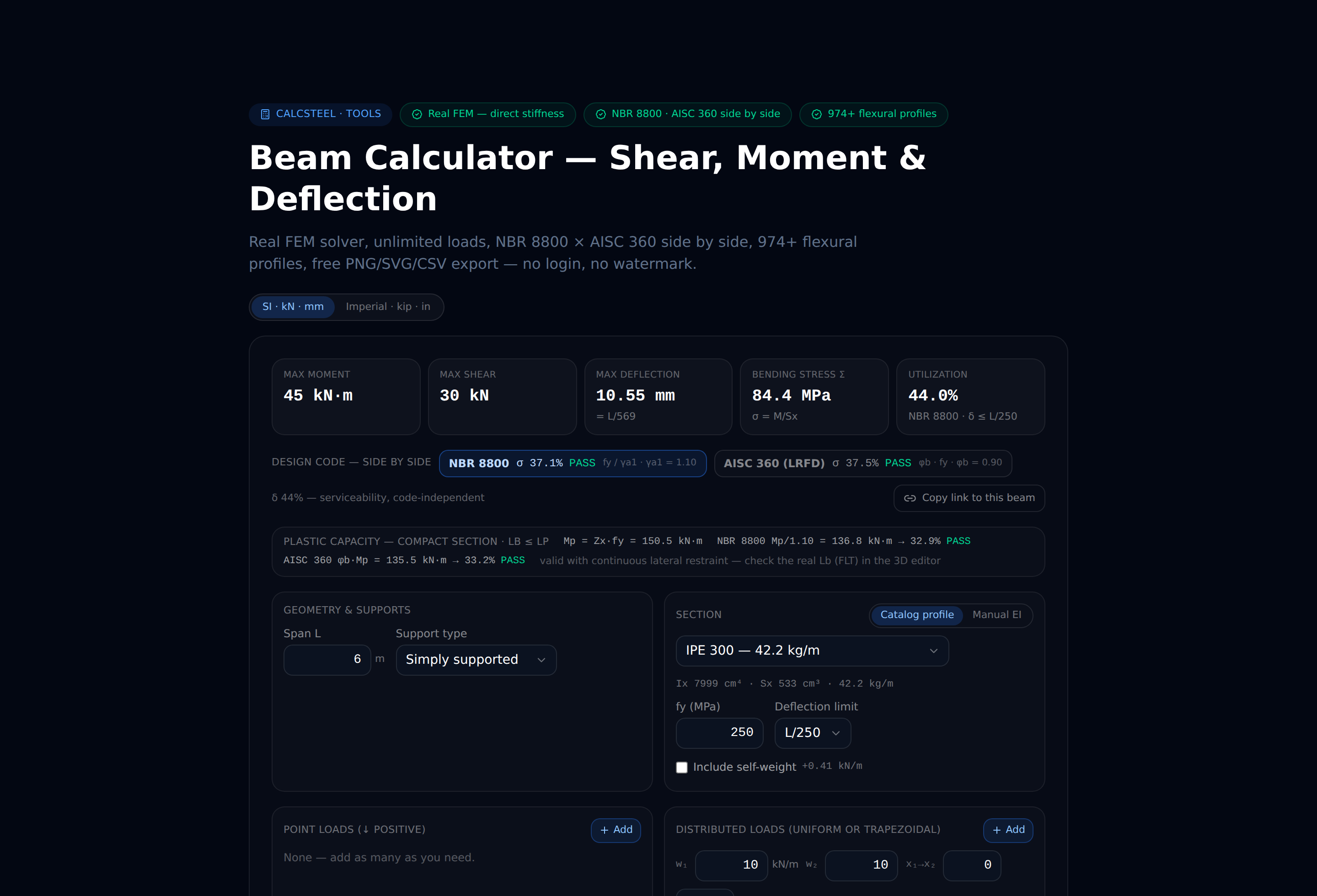
Max moment
45 kN·m
Max shear
30 kN
Max deflection
10.55 mm
= L/569
Bending stress σ
84.4 MPa
σ = M/Sx
Utilization
44.0%
NBR 8800 · δ ≤ L/250
Geometry & supports
Section
Ix 7999 cm⁴ · Sx 533 cm³ · 42.2 kg/m
Point loads (↓ positive)
None — add as many as you need.
Distributed loads (uniform or trapezoidal)
Model sketch
Diagrams — free PNG / SVG / CSV export, no watermark
Step-by-step — the calculation memory of YOUR beam
IPE 300 · L = 6 m · fy = 250 MPa
1. Reactions (equilibrium of the solved FEM model)
ΣFy = 0 · ΣM = 0
R_A = 30 kN · R_B = 30 kN
2. Peak shear (read from the SFD)
Vmax = |V(x)|max
Vmax = -30 kN @ x = 6 m
3. Peak moment (read from the BMD)
Mmax = |M(x)|max
Mmax = 45 kN·m @ x = 3 m
4. Peak deflection
EI = 15998 kN·m² (E = 200 GPa)
δmax = 10.55 mm @ x = 3 m = L/569
5. Elastic bending stress
σ = Mmax / Sx = 45.00 × 10³ / 533.3
σ = 84.4 MPa
6. Bending check — both codes, side by side
NBR 8800: σ ≤ fy/1.10 = 227.3 MPa · AISC 360: σ ≤ 0.90·fy = 225 MPa
NBR 37.1% PASS · AISC 37.5% PASS
7. Deflection check (serviceability — code-independent)
δ ≤ L/250 = 24 mm
10.55 mm / 24 mm = 44.0% PASS
Recomputed live from the current inputs by the direct-stiffness FEM engine — change any load and every step updates. Reproduce it by hand with the formulas in the sections below.
Lightest catalog profiles that pass (974 flexural candidates · NBR 8800)
| Profile | Std | Weight | Total steel | σ util | δ util | |
|---|---|---|---|---|---|---|
| W310x21 | AISC | 21 kg/m | 126 kg | 83% | 98% | |
| VS 300x23 | BR | 22.6 kg/m | 136 kg | 71% | 84% | |
| U 300x90x6.3 | BR | 23.1 kg/m | 139 kg | 82% | 98% | |
| U 300x100x6.3 | BR | 24.1 kg/m | 145 kg | 77% | 91% | |
| VS 250x25 | BR | 24.6 kg/m | 148 kg | 70% | 100% |
Elastic bending (σ = M/Sx vs fy/γa1, γa1 = 1.10 — NBR 8800) + deflection screening of the full flexural catalog. Lateral-torsional buckling, shear and local buckling are NOT checked here — run the full NBR 8800 / AISC 360 verification in the 3D editor.
Putting it to work
Deflection limits are the quiet half of structural design: rarely the reason a frame is unsafe, often the reason it is unpleasant or unsellable. The recurring theme across NBR 8800, AISC/IBC, Eurocode 3 and IS 800 is the same span-proportional logic that Tredgold sketched two centuries ago, now wrapped in code-specific tables, load cases and national choices.
Three habits keep you out of trouble. First, treat the SLS check as a first-class step, not an afterthought to strength: it is governed by service loads and frequently controls long, lightly loaded members. Second, read the actual table and its footnotes for the code you are working under, because the limit changes with finish, load case and, in Europe, the National Annex. Third, let the model do the bookkeeping: a tool that builds serviceability combinations, measures sag relative to the member chord, deducts camber where allowed, and reports a per-member utilisation turns a fiddly hand calculation into a one-line verdict.
Get those right and the deflection check stops being a box to tick and becomes what it was always meant to be: a guarantee that the building feels as solid as the numbers say it is.
Sources
- 1.AISC Design Guide 3: Serviceability Design Considerations for Steel Buildings (2nd Ed., 2003), West & Fisher
- 2.2021 International Building Code, Section 1604.3 / Table 1604.3 Deflection Limits
- 3.EN 1993-1-1:2005 Eurocode 3: Design of steel structures (clauses 7.2.1/7.2.2 and National Annexes)
- 4.IS 800:2007 General Construction in Steel (Table 6, deflection limits)
- 5.ABNT NBR 8800:2008, Anexo C, Deslocamentos Máximos
- 6.Novidades da ABNT NBR 8800:2024 (Anexo C agora informativo), Gerdau Mais
- 7.Image: Peikko, Public domain (Wikimedia Commons)
Try CalcSteel for free
Model, analyze and design steel structures in your browser. No install, no signup.
Open the 3D editor