Cross Braced Frame: the Tension-Only Criterion Behind the Code, and the Factor of 2 It Decides
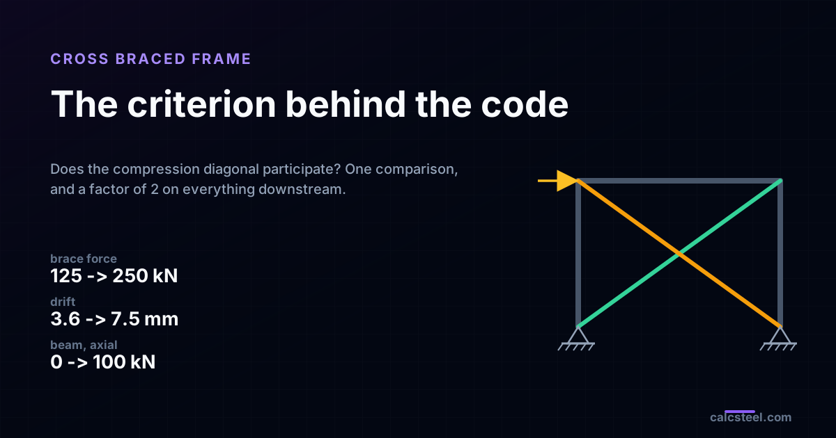
A cross braced frame is two diagonals in an X taking the story shear down to the foundation, and it is the most drawn lateral system in steel. What the drawing never says is which of the two diagonals is allowed to work. That one decision doubles the force in the surviving diagonal, doubles the drift of the bay, turns the beam into a collector carrying half the story shear, and leaves the overturning couple at the base untouched. This article runs the same 6.0 m by 4.5 m bay on the shipping CalcSteel FEM engine under both answers, checks every number against statics, and finds the check the tension-only bay actually fails. It is not strength.
Key takeaways
- The criterion is one comparison: the design compression strength of the compression diagonal, at its real effective length, against V / (2 cos theta). Pass and the two diagonals share the story shear. Fail and one diagonal carries all of it, and every number downstream changes.
- The split itself is statics, not analysis. Sharing gives plus and minus V / (2 cos theta) = 125.0 kN. Tension only gives V / cos theta = 250.0 kN. The engine returned both to the third decimal, a difference of 0.000 %.
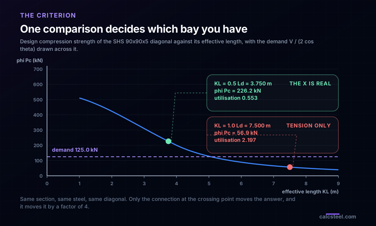
- The whole decision lives in one connection. An SHS 90x90x5 diagonal at KL = 3.750 m has phi Pc = 226.2 kN, a utilisation of 0.553, and passes. The same diagonal at KL = 7.500 m has phi Pc = 56.9 kN, a utilisation of 2.197, and fails. The connection at the crossing point is worth a factor of 4.
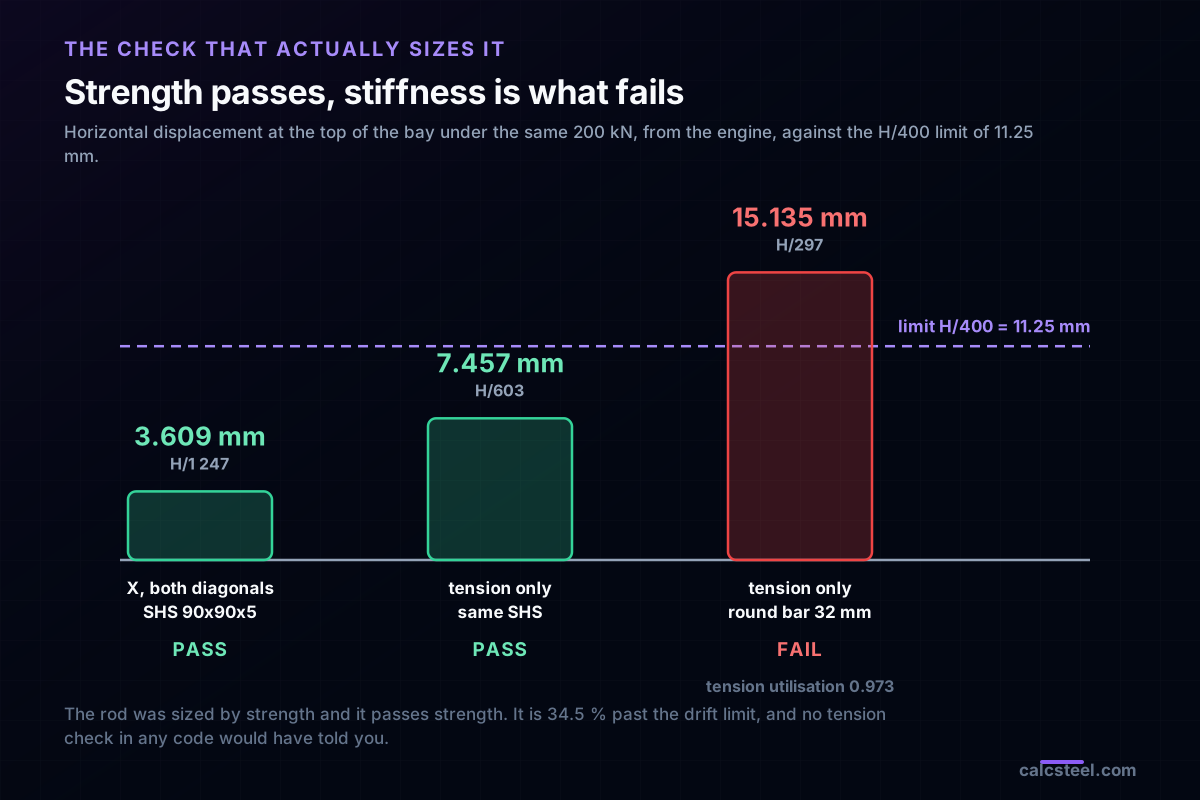
- Drift doubles on identical steel: 3.609 mm, which is H/1247, against 7.457 mm, which is H/603. The engine returns a ratio of 2.066, and the 3 % over the clean factor of 2 is the columns shortening under the vertical component of the brace.
- The check the tension-only bay fails is stiffness, not strength. The 32 mm rod sits at 0.973 of its design tension capacity, a pass by any code, and drifts 15.135 mm, which is H/297 and 34.5 % past an H/400 limit.
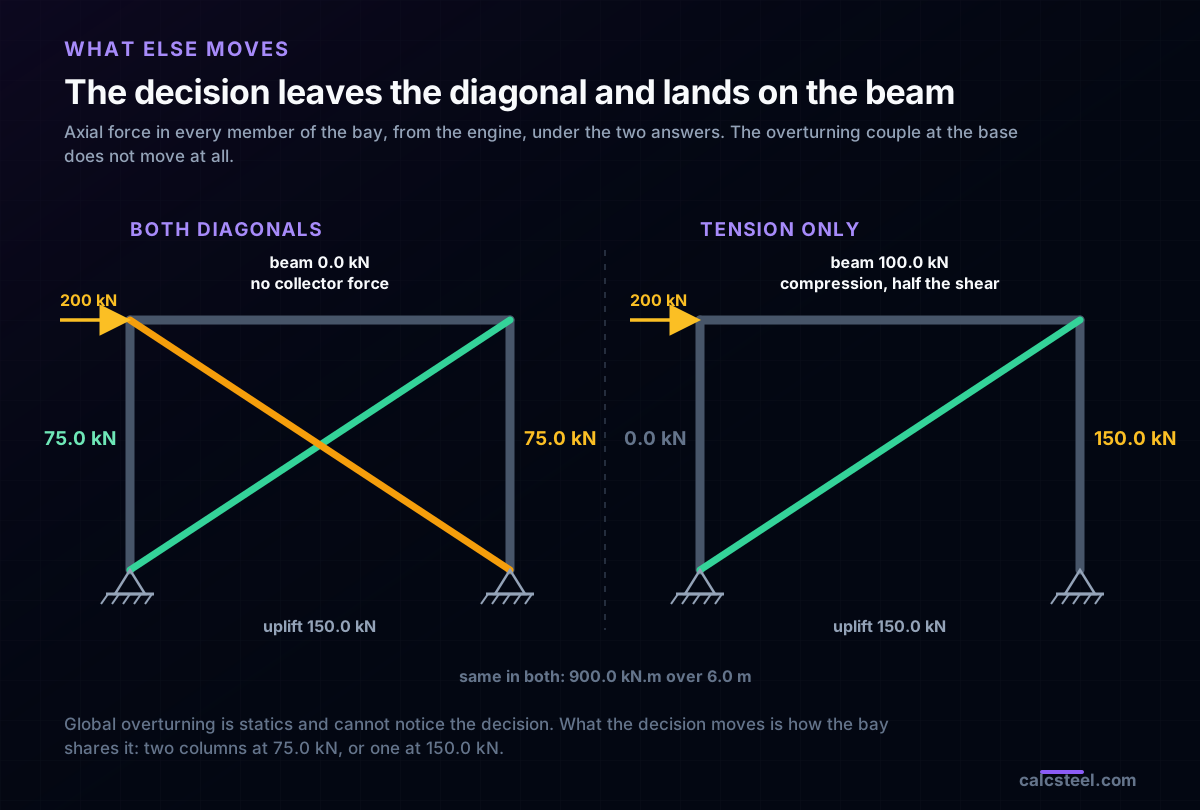
- The beam stops being only a beam. Sharing leaves it at 0.0 kN of axial force. Tension only puts 100.0 kN of compression in it, exactly half the story shear, because the load applied at the far top node has to travel the length of the beam to reach the one diagonal that works.
- That collector force costs this beam 6.6 % of its capacity: the interaction ratio goes from 0.4366 to 0.4652 once the 100.0 kN is applied with the gravity moment. Small, real, and completely absent from a model that never applied it.
- Overturning does not move at all. 900.0 kN.m over a 6.0 m arm is 150.0 kN of base uplift under both answers, because global statics cannot see a modelling decision. What moves is who carries it: two columns at 75.0 kN, or one column at 150.0 kN and nothing in the other.
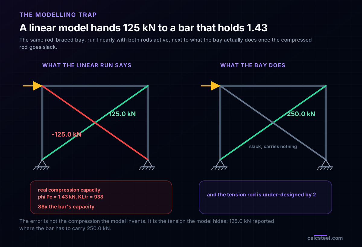
- A linear run of a rod-braced X is wrong twice over. It invents 125.0 kN of compression in a bar whose design compression strength is 1.43 kN, which is 88 times over, and it reports 125.0 kN of tension where the surviving rod has to carry 250.0 kN. The unconservative half is the one nobody looks at.
- The X exists for reversal. Reverse the load and the engine hands the mirror diagonal the same 250.0 kN. A single diagonal would have to take that in compression, at KL/r = 938 for a 32 mm rod, which is not a structure.
- Decide first, then model. A tension-only bay is a different structure from a sharing bay, not the same structure analysed loosely, and the two differ by a factor of 2 in the three numbers that size it.
One X, two answers, and a factor of 2
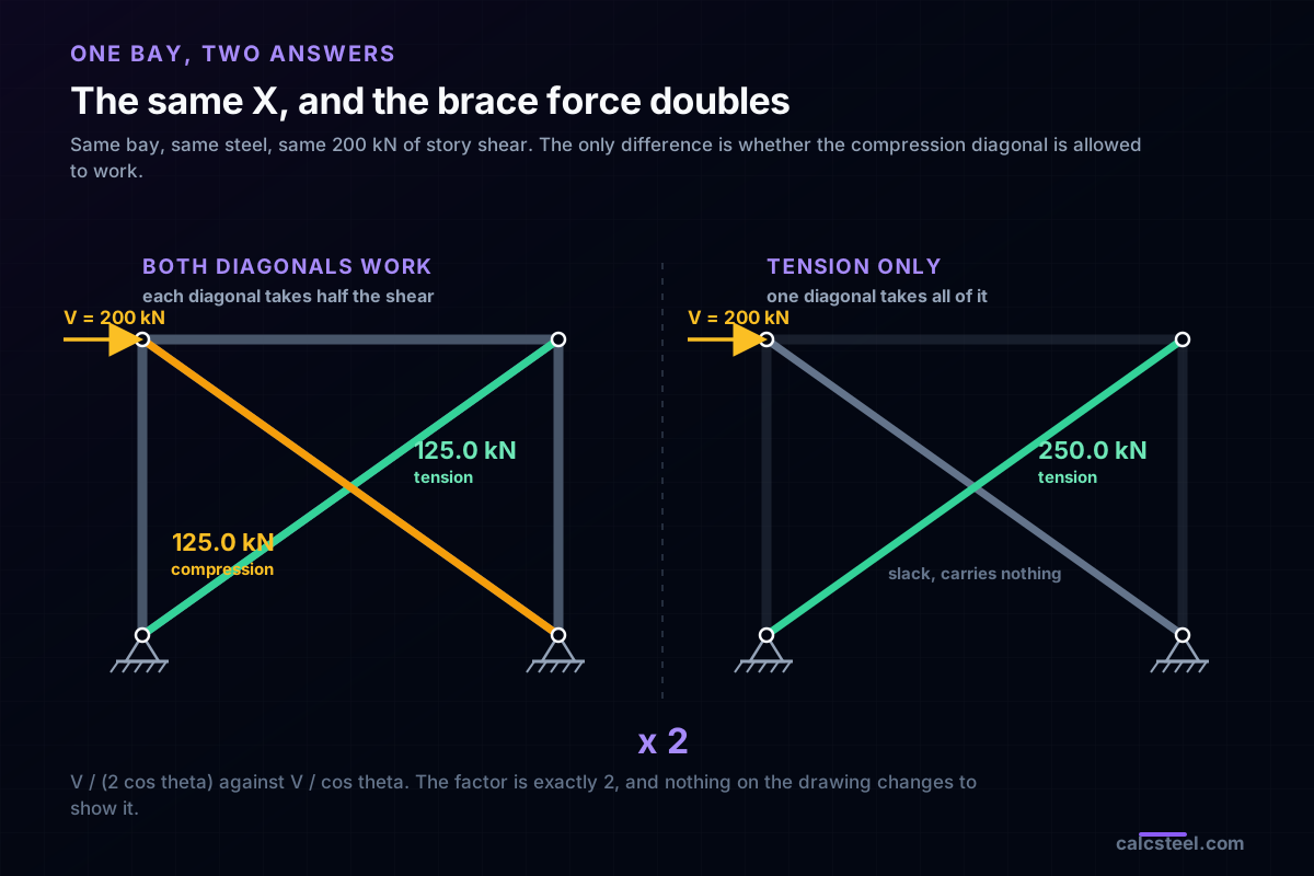
Here is a bay: 6.0 m wide, 4.5 m to the underside of the beam, two columns, one beam, two diagonals crossing in an X. A story shear of 200 kN arrives at beam level. Any engineer can size the diagonal in a minute, and two engineers given this drawing will hand back answers that differ by a factor of 2.
Not because one of them is careless. Because the drawing does not say whether the compression diagonal is allowed to work. If it is, each diagonal takes half the story shear and the demand is 125.0 kN. If it is not, the tension diagonal takes all of it and the demand is 250.0 kN. Same bay, same steel, same load, same drawing.
This is not an argument about safety factors. It is a question with an answer, the answer is a single comparison, and everything downstream of it moves: the drift of the bay, the axial force in the beam, how the two columns split the overturning. Below, the same bay is run on the CalcSteel finite element engine under both answers, and every published number is checked against the hand calculation it should reproduce.
What a cross braced frame is, and what the X is for
A cross braced frame, also called an X-braced frame, is a bay of a concentrically braced frame in which two diagonals run corner to corner and cross near mid-length. Its job is to take the horizontal load at each floor and turn it into axial force in a triangle, so it reaches the foundation without asking any member to bend. Compared with a moment frame it is stiffer for far less steel, and compared with a shear wall it is lighter and leaves the bay open.
The reason there are two diagonals and not one is reversal. Wind and earthquake both push a building one way and then the other. A single diagonal that works beautifully in tension under a push from the left has to work in compression under a push from the right, over its full unbraced length, which is the longest dimension in the bay. The second diagonal is there so that whichever way the load comes, there is always a diagonal in tension to take it.
That is the whole idea, and it is why the X is drawn. What the drawing leaves open is the follow-up question: when the load comes from the left and one diagonal is in tension, is the other one also carrying load, in compression, or is it just standing there?
The question the drawing does not answer
Take the bay under a story shear V, with the diagonal at an angle theta to the horizontal. Cut the bay with a horizontal plane just below the beam and write horizontal equilibrium of the piece above the cut. The only members crossing the cut are the two columns, which carry no horizontal force in a simple frame, and the diagonals.
If both diagonals are counted, one in tension and one in compression, they share: each takes V / (2 cos theta). If only the tension diagonal is counted, it takes V / cos theta, twice as much. There is nothing in between that you can rely on. The bay is either a tension-compression system or a tension-only system, and which one it is depends on whether the compression diagonal can actually carry its share without buckling.
This is a real design decision that is taken all the time, usually without being written down. Rod bracing and flat-bar bracing are tension only by construction, because a 32 mm rod is a piece of string in compression. Tube and angle bracing is usually tension-compression, but only if the compression diagonal has been checked at the right effective length. Between those two sits a large population of bays that were drawn as an X, modelled with both diagonals active, and detailed as if they were tension only.
The criterion behind the code, from first principles
Stripped to its core, the criterion is one comparison:
The compression diagonal participates if, and only if, its design compression strength at its real effective length is at least V / (2 cos theta).
Every code writes this the same way, because it is not really a code rule, it is a statement about which load path exists. AISC 360 gives the compression strength in Chapter E, where the flexural buckling stress depends on the slenderness KL/r through the elastic buckling stress Fe = pi squared E / (KL/r) squared. EN 1993-1-1 writes it as a reduction factor chi applied to A fy. Both have the same shape and the same consequence: compression strength falls off with the square of the effective length, so what you assume about KL is worth far more than what you assume about the steel grade.
And that is where the X earns its keep. When the two diagonals run continuous through the crossing and are attached to each other there, the compression diagonal is braced at that point by the diagonal in tension, and its effective length drops to about half the full diagonal. Because the capacity goes with the square, halving KL is worth a factor of about 4. Letting them simply pass each other throws that away, and splicing one diagonal at the crossing is worse than nothing: the splice becomes the weak link exactly when the interrupted diagonal is the one in compression.
It is worth being exact about where the two halves of this come from, because they do not carry the same authority. Turning KL into a design strength is code, and Chapter E of AISC 360 and Section 6.3 of EN 1993-1-1 both do it. The value KL = 0.5 L for an X is not a specification clause anywhere. It comes from Picard and Beaulieu, whose 1987 study derives 0.5 as the practical floor for diagonals that are continuous and connected at the intersection, and it reaches the AISC codes only as commentary, scoped to the special segment of a truss moment frame. Treat it as a well-founded recommendation with a detailing condition attached, not as a number the code hands you.
The figure below is the same SHS 90x90x5 diagonal, the same steel, evaluated across a range of effective lengths, with the demand drawn across it. At KL = 3.750 m, half the diagonal, the design strength is 226.2 kN against a demand of 125.0 kN, a utilisation of 0.553. At KL = 7.500 m, the full diagonal, the design strength is 56.9 kN, a utilisation of 2.197. One connection detail, and the same steel goes from comfortable to more than twice overloaded.
The bay, and where every number below comes from
The worked example is deliberately a 3-4-5 triangle, so that every hand check is exact and nothing hides behind rounding:
- Bay 6.0 m wide, 4.5 m high, so the diagonal is exactly 7.5 m long at 36.87 degrees, and cos theta = 0.8 exactly.
- Story shear V = 200 kN, applied half at each top node, which is what two columns of tributary width deliver.
- Columns HEB 200, beam IPE 330, diagonals SHS 90x90x5 with A = 1700 mm2 and r = 34.76 mm, or a 32 mm round bar with A = 804.2 mm2 and r = 8.00 mm. Steel S355 throughout.
- Simple frame: the columns are pinned at the base and the beam-to-column joints carry shear only, so the diagonals are the only lateral load path and the brace force is statically determinate.
- Drift limit H/400, which is 11.25 mm for a 4.5 m story. That is the top-of-columns-against-the-base row of NBR 8800 Annex C, and it sits at the loose end of the 1/600 to 1/400 range the ASCE 7 commentary suggests. It is not an inter-storey limit: NBR 8800 puts that one at h/500, and EN 1993-1-1 gives no number at all and leaves it to the National Annex.
Every member force and every displacement quoted below came out of app.engine.solver.run_analysis, the same finite element engine that runs behind the CalcSteel editor, and each one is asserted in the benchmark script against the closed-form value it has to reproduce. Where the engine and the hand calculation differ, the difference is reported rather than smoothed over.
One modelling note that matters more than it looks: the story shear is applied half at each top node. That is the honest tributary assumption for a bay flanked by two columns, and it is also the assumption that makes the beam axial force come out the way it does. Put the whole 200 kN at one node and the collector force in the beam changes, which is itself worth knowing.
Worked check, part 1: the split, against statics
Two models, identical except for the diagonals. In the first, both diagonals are present. In the second, only the tension diagonal is present, which is exactly what a tension-only design assumes.
Hand calculation first. With V = 200 kN and cos theta = 0.8:
- Sharing: V / (2 cos theta) = 200 / 1.6 = 125.0 kN, one diagonal in tension and one in compression.
- Tension only: V / cos theta = 200 / 0.8 = 250.0 kN, all of it in one diagonal.
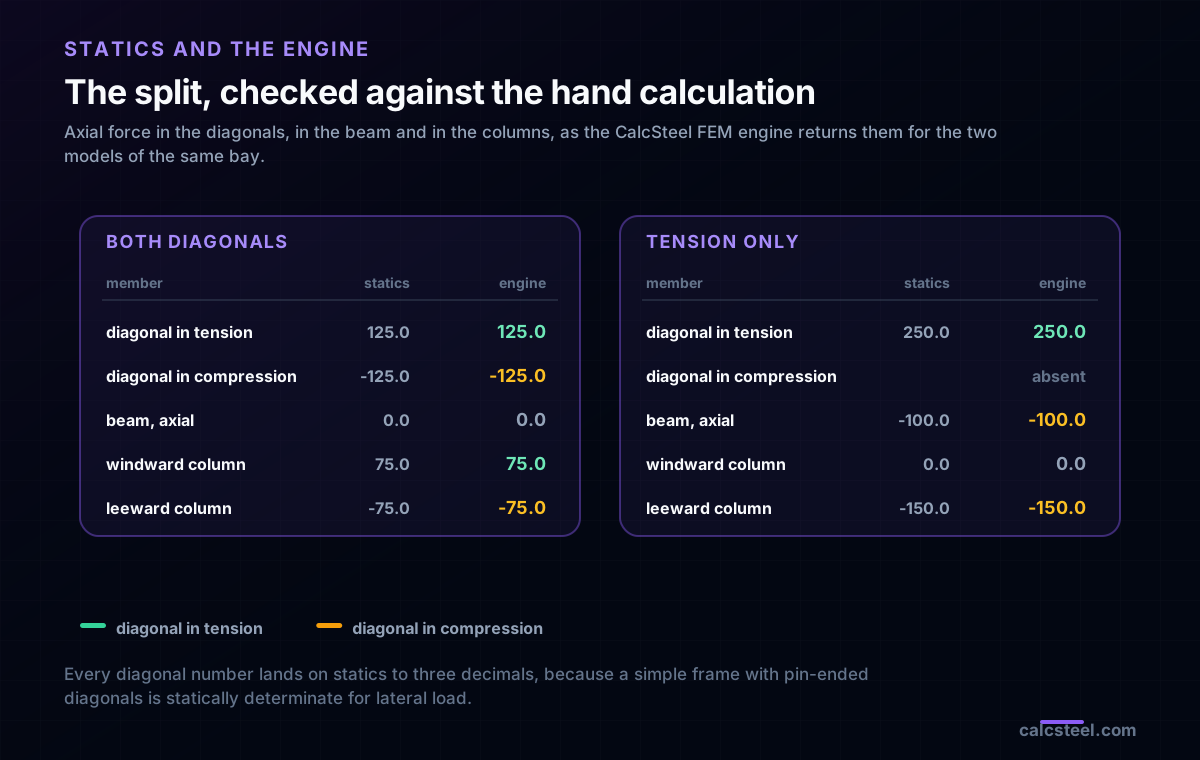
The engine returned 125.0 kN and minus 125.0 kN for the pair, and 250.0 kN for the single diagonal. The difference against statics is 0.000 % in both cases, which is what a determinate load path should give: a simple frame with pin-ended diagonals has exactly one way to carry lateral load, and the analysis has no freedom to find another.
That agreement is worth stating plainly, because it is the reason the rest of this article can be trusted. The engine is not being asked to reveal anything mysterious about the split. It is being asked to confirm the split, and then to tell us the things statics cannot: the drift, and what happens in the members that are not diagonals.
Worked check, part 2: does the compression diagonal make it?
Now apply the criterion to the actual section. The SHS 90x90x5 has A = 1700 mm2 and r = 34.76 mm, and the demand if the diagonals share is 125.0 kN.
With the crossing connection, KL = 0.5 times 7.5 = 3.750 m. That gives KL/r = 107.9, an elastic buckling stress Fe = 169.6 MPa, a critical stress Fcr = 147.8 MPa and a design strength of 226.2 kN. Utilisation 0.553. The compression diagonal participates, the bay is a genuine tension-compression system, and the 125.0 kN split is real.
Without it, KL = 7.500 m. KL/r climbs to 215.8, Fe collapses to 42.4 MPa, Fcr to 37.2 MPa, and the design strength is 56.9 kN against the same 125.0 kN demand. Utilisation 2.197. The compression diagonal does not participate, whatever the analysis model says, and the bay is a tension-only system carrying 250.0 kN in one diagonal.
Notice what did not change between those two paragraphs. Not the section, not the steel grade, not the load, not the geometry. Only the assumption about K, and it moved the capacity by a factor of 4. This is why the criterion is worth writing on the drawing: the person detailing the crossing connection is deciding the design, and usually does not know it.
For completeness, the same section in tension has a design strength of 543.1 kN, a utilisation of 0.230 against the 125.0 kN. Tension is never the problem in a braced bay. Compression and stiffness are.
Try it: move KL and watch the criterion flip
The comparison above is the whole criterion, and it is worth doing yourself. Put in the SHS 90x90x5, S355, and set the length to 3.750 m with K = 1.0, which is the X with its crossing connection. Then set the length to 7.500 m, which is the same diagonal without it. Watch the buckling curve, the slenderness and the design capacity move while nothing else does.
The demand to compare against is 125.0 kN if the diagonals share the shear, and 250.0 kN if they do not.
End conditions (buckling case)
Pinned – Pinned
Cross-section
Slenderness KL/r
134.7
limit 200 · OK
Euler Pcr (elastic)
310.7 kN
Fe = 108.9 MPa
AISC 360 φcPn
245.2 kN
Fcr = 95.5 MPa · elastic
NBR 8800 Nc,Rd
247.7 kN
χ = 0.382 · λ₀ = 1.52
Code vs code — same column
Nc,Rd / φcPn = 1.010
Both codes share the 0.658 / 0.877 buckling curve — the ~1% gap is purely φc = 0.90 (AISC) vs 1/γa1 = 0.909 (NBR).
Demand check — Nd = 150 kN
Step-by-step derivation — live for YOUR column
IPE 200 · L = 3 m · K = 1 · fy = 250 MPa
- 1
Slenderness ratio
λ = K·L/r = 1 × 3000 / 22.28 mm
λ = 134.7 (≤ 200 ✓)
- 2
Euler elastic buckling stress and load
Fe = π²E/λ² = π² × 200,000 / 134.7² · Pcr = Fe·A = Fe × 2854 mm²
Fe = 108.9 MPa · Pcr = 310.7 kN
- 3
Buckling regime (AISC E3)
4.71·√(E/fy) = 4.71·√(200,000/250) = 133.2 < λ = 134.7
elastic buckling → use E3-3 (0.877·Fe)
Elastic range: capacity no longer depends on fy — only geometry (r, K, L) helps.
- 4
AISC 360 critical stress and design capacity
Fcr = 0.877 · Fe = 0.877 × 108.9 = 95.5 MPa · φcPn = 0.9 × Fcr × A
Pn = 272.5 kN · φcPn = 245.2 kN
- 5
NBR 8800 reduction factor and design capacity
λ₀ = √(fy/Fe) = 1.515 > 1.5 → χ = 0.877/λ₀² = 0.382 · Nc,Rd = χ·A·fy/1.1
Nc,Rk = 272.5 kN · Nc,Rd = 247.7 kN
Same 0.658/0.877 curve as AISC — the ~1% difference is φc = 0.90 vs 1/γa1 = 0.909.
Sections that work — 3 lightest of 612 catalog profiles carrying Nd = 150 kN at L = 3 m, K = 1
| Section | kg/m | φcPn (kN) | Nc,Rd (kN) | Util. | |
|---|---|---|---|---|---|
| lightestSHS 80x4 | 9.2 | 164 | 166 | 91% | |
| HSS 76x76x4.8 | 9.9 | 165 | 167 | 91% | |
| CHS 88.9x5 | 10.3 | 172 | 174 | 87% |
Pass criterion: φcPn ≥ Nd (AISC 360 LRFD) AND Nc,Rd ≥ Nd (NBR 8800) AND KL/r ≤ 200, using each section's tabulated-mass area and minimum radius of gyration.
Buckling curve — IPE 200, fy = 250 MPa
Capacity of IPE 200 by unbraced length — K = 1, fy = 250 MPa
| L (m) | KL/r | Pcr Euler (kN) | φcPn AISC (kN) | Nc,Rd NBR (kN) | Regime |
|---|---|---|---|---|---|
| 1 | 45 | 2,796 | 577 | 583 | inelastic |
| 2 | 90 | 699 | 419 | 423 | inelastic |
| 3◀ yours | 135 | 311 | 245 | 248 | elastic |
| 4 | 180 | 175 | 138 | 139 | elastic |
| 5 | 224 ⚠ | 112 | 88 | 89 | elastic |
| 6 | 269 ⚠ | 78 | 61 | 62 | elastic |
| 7 | 314 ⚠ | 57 | 45 | 45 | elastic |
| 8 | 359 ⚠ | 44 | 34 | 35 | elastic |
| 9 | 404 ⚠ | 35 | 27 | 28 | elastic |
| 10 | 449 ⚠ | 28 | 22 | 22 | elastic |
Worked check, part 3: the check that actually sizes the bay
Strength was never the binding check here, and this is where the article earns its keep. The three bays below carry the same 200 kN and differ only in the diagonals.
- X, both diagonals, SHS 90x90x5: 3.609 mm, which is H/1247. Closed form gives 3.447 mm, a difference of 4.70 %.
- Tension only, the same SHS: 7.457 mm, which is H/603. Closed form 6.893 mm, a difference of 8.18 %.
- Tension only, 32 mm rod: 15.135 mm, which is H/297. Closed form 14.571 mm, a difference of 3.87 %.
The first two are the same steel. Removing the compression diagonal from the load path multiplies the drift by 2.066, and the closed form says it should be exactly 2, because the bay has half as many springs resisting the same load. The extra 3 % is the columns shortening under the vertical component of the brace force, which the closed form ignores and the engine does not.
The third line is the one that matters. The 32 mm rod was sized by strength: 250.0 kN demand against a design tension capacity of 257.0 kN, a utilisation of 0.973. It passes. It also drifts 15.135 mm against a limit of 11.25 mm, which is 34.5 % over. Nothing in the tension check, in any code, would have told you that. The rod is strong enough and the bay is not stiff enough, and those are different questions.
This is the general shape of braced-frame design, and it is why experienced engineers size braces by stiffness and then check strength rather than the other way around. In a braced bay the strength check is usually comfortable and the drift check is usually tight, so the participation decision, which halves the stiffness, hits exactly the check that governs.
What else moves: the beam becomes a collector
The diagonal is the member everybody checks. The interesting consequences of the participation decision are in the members nobody checks.
| What the engine returned | Both diagonals | Tension only |
|---|---|---|
| Diagonal in tension | 125.0 kN | 250.0 kN |
| Diagonal in compression | 125.0 kN | absent |
| Beam, axial force | 0.0 kN | 100.0 kN compression |
| Windward column, axial | 75.0 kN tension | 0.0 kN |
| Leeward column, axial | 75.0 kN compression | 150.0 kN compression |
| Base uplift | 150.0 kN | 150.0 kN |
Two things in that table are worth more than the diagonal numbers.
The beam. When both diagonals work, each top node has its own diagonal to send its 100 kN down, and the beam carries no axial force at all: 0.0 kN. When only one diagonal works, the 100 kN applied at the far top node has nowhere to go except along the beam, so the beam picks up 100.0 kN of compression, exactly half the story shear. It has become a collector, and it now has to be checked for axial force and bending together. On this beam, with 25 kN/m of gravity giving a 112.5 kN.m moment against a design capacity of 257.7 kN.m, the interaction ratio goes from 0.4366 to 0.4652 once the collector force is included. That is 6.6 % of capacity: not a crisis, and not zero, and entirely invisible to a model that never applied it.
The base does not move. Overturning is 200 kN times 4.5 m = 900.0 kN.m, resisted by a couple over the 6.0 m bay, which is 150.0 kN of uplift. The engine returns 150.0 kN under both models, because global statics cannot see a modelling decision. What the decision changes is how the bay shares that couple internally: two columns at 75.0 kN each, or one leeward column at 150.0 kN with the whole uplift delivered straight into the brace connection at the windward base. Same anchor force, very different column and gusset.
Reversal, and why one diagonal is not a cross braced frame
Everything above was computed with the load pushing one way. Reverse it and the engine hands the mirror diagonal the same 250.0 kN, in tension, with the first diagonal now going slack. That symmetry is the entire reason the second diagonal is drawn, even in a bay where it is never expected to carry compression.
Which is the precise sense in which a tension-only X is still a cross braced frame. The two diagonals are not redundant and they are not sharing: they are taking turns. Each is the whole lateral system for one direction of load, which is why each has to be sized for the full V / cos theta and not for half of it.
Delete one of them and you have a single-diagonal braced bay, which is a different structure. It has to work in compression under reversed load, over its full 7.5 m, which is fine for a tube and impossible for a rod: a 32 mm rod at KL/r = 938 has a design compression strength of 1.43 kN. Not 143. 1.43 kN. That is the number that separates the two systems, and it is why rod and flat bracing is always drawn as a pair.
The linear model that hides half the tension
Here is the failure mode this article exists to prevent. Model the rod-braced bay the obvious way, with both rods present as ordinary truss members, run a linear elastic analysis, and read off the brace forces. The engine returns 125.0 kN in one rod and minus 125.0 kN in the other, because a linear analysis has no way to know a rod cannot push.
That result is wrong twice, and only one of the two errors is the one people talk about.
- The visible error: 125.0 kN of compression in a bar whose design compression strength is 1.43 kN. The model is over by a factor of 88. This one is easy to catch, because it is absurd on its face and the compression check screams.
- The error that gets built: the same run reports 125.0 kN of tension in the working rod, when the rod actually has to carry 250.0 kN. The model under-states the demand on the one member that matters by a factor of exactly 2, and the tension check passes comfortably, and nothing screams.
The fix is not a bigger factor of safety. It is to model what you detailed. Either remove the compression diagonal from the model for each direction of load and run both directions, or use a tension-only element that drops out of the stiffness matrix when it goes into compression, which makes the analysis nonlinear per load case. Both give 250.0 kN. The linear X with both rods gives 125.0 kN, and it will keep giving it, quietly, for as long as nobody asks.
Rods, flats and L/r: the cap, the exception and the sag
Tension members carry load regardless of how slender they are, and AISC 360 says exactly that in the mandatory text of Section D1: there is no maximum slenderness limit for members in tension. The 300 that everybody quotes sits immediately below that sentence, in a user note, which makes it a suggestion and not a requirement: L/r for members designed on the basis of tension preferably should not exceed 300. The same note then exempts rods and hangers from the suggestion.
Which is fortunate, because the 32 mm rod in this bay has L/r = 938, a little over three times the cap it is exempt from. The exemption is not a loophole: it exists because the reason for the 300 is to stop members sagging, vibrating and being damaged in handling, and a rod bracing system deals with all three by being pretensioned, usually through a turnbuckle, and by being detailed so that nobody walks on it.
Two practical consequences follow, and neither is in the tension check:
- Pretension is part of the design. A slack rod does nothing until it has taken up its own sag, which shows up as extra drift before the system even engages, on top of the 15.135 mm computed above.
- Stiffness, not strength, sets the size. The rod that passes tension at a utilisation of 0.973 has to be grown for drift, and because drift scales with 1/A, the section has to grow by at least the ratio the drift is over: roughly a third more area.
For the seismic case the participation question stops being a judgement and becomes code text, and the two big codes answer it in opposite directions. AISC 341 says a special concentrically braced frame shall not be tension only, caps the braces at an Lc/r of 200, and then makes you check the columns, beams, struts and connections against two analyses: one with every brace at its expected strength, and one with the tension braces at expected strength while the compression braces are down to a post-buckling residue the code caps at 0.3 times their expected compression strength. Eurocode 8 goes the other way and makes tension only mandatory: in frames with diagonal bracings, only the tension diagonals shall be taken into account in the elastic analysis.
Put those two side by side and the subject of this article is code text, not opinion. One forbids you to design the X as tension only and then makes you analyse it as though it were. The other simply orders you to analyse it as tension only. Neither of them lets you keep the 125.0 kN.
Eight things that go wrong
- Sizing the diagonal for V / (2 cos theta) and detailing it as tension only. The commonest version of this article's whole subject. The brace is built at half the force it will see.
- Assuming KL = 0.5 L because the drawing shows an X. The halving comes from diagonals that run continuous through the crossing and are attached there, not from the shape. If they simply pass each other, or if one of them is spliced at the crossing, the compression diagonal is not braced at midpoint, and in this bay that is 56.9 kN of capacity against 125.0 kN of demand.
- Running a linear model with both rods active. It invents compression that cannot exist and halves the tension that does. The half is the dangerous part.
- Checking the brace and stopping. The beam picked up 100.0 kN of axial force in the tension-only model and nobody applied it. On this beam it is 6.6 % of capacity; on a longer, lighter beam it is more.
- Sizing by strength in a system governed by stiffness. The rod passes tension at 0.973 and misses drift by 34.5 %. Check drift first.
- Expecting the base uplift to change. It does not: 150.0 kN either way, because 900.0 kN.m over 6.0 m is statics. What changes is the column axial split, 75.0 kN each against 150.0 kN in one.
- Forgetting that the drift limit applies to the bare frame you modelled. Cladding, partitions and connection slip all move the real number in the wrong direction, and a bay at H/603 has room for that while a bay at H/297 does not.
- Treating a single diagonal as a cross braced frame. It has to take the reversed load in compression over its full length. For a rod that is 1.43 kN of capacity, and the system does not exist in that direction.
What to actually do
The sequence that keeps a cross braced frame honest is short, and the order matters more than any individual step.
- Decide participation first, on paper. Compute phi Pc of the compression diagonal at the effective length the connection detail will actually deliver, and compare it to V / (2 cos theta). Write the answer on the drawing.
- Model the system you decided on. Tension only means one diagonal per direction of load, or tension-only elements. Sharing means the crossing connection is a structural requirement, not a detail.
- Check drift before strength. In a braced bay strength is usually comfortable and drift is usually the constraint, and the participation decision doubles the drift.
- Read the beam and column axial forces out of the model. The collector force in the beam is half the story shear in a tension-only bay and zero in a sharing one, and the leeward column axial doubles.
- Check both directions of load. Not for symmetry's sake: to confirm that the mirror diagonal really does pick up the full V / cos theta, and that the bay is complete in both directions.
- Re-check after any change to the crossing detail. It is the one connection whose detailing decides which structure you built.
The factor of 2 in the title is not an accident of this example. It is 1 / (2 cos theta) against 1 / cos theta, so it is exactly 2 for every bay, at every angle, in every bay width. What changes from bay to bay is only how much that factor of 2 costs you.
Sources
- 1.AISC 360, Specification for Structural Steel Buildings: Chapter E for the compression strength and the flexural buckling stress, and Section D1, whose mandatory text states there is no maximum slenderness limit for members in tension and whose user note adds the L/r of 300 and its exemption for rods and hangers
- 2.AISC 341, Seismic Provisions for Structural Steel Buildings: Section F2, which prohibits tension-only special concentrically braced frames, caps the brace Lc/r at 200, and requires the frame to be checked against both the expected-strength and the post-buckling analyses
- 3.EN 1993-1-1, Eurocode 3, design of steel structures, general rules: Section 6.3 for the buckling reduction factor and the buckling curves, and Section 7.2.2, which sets no horizontal deflection limit and defers it to the National Annex
- 4.EN 1998-1, Eurocode 8, design of structures for earthquake resistance: clause 6.7.2, which requires that in frames with diagonal bracings only the tension diagonals be taken into account in the elastic analysis, and clause 6.7.3, which bounds the brace slenderness of X-braced frames
- 5.ABNT NBR 8800, Projeto de estruturas de aco e de estruturas mistas de aco e concreto: the compression resistance, and Annex C Table C.1, which limits the horizontal displacement of the top of the columns relative to the base to H/400 and the displacement between consecutive floors to h/500
- 6.ASCE 7, Minimum Design Loads and Associated Criteria for Buildings and Other Structures: the non-mandatory appendix on serviceability, which suggests drift limits of the order of 1/600 to 1/400 of the building or story height
- 7.A. Picard and D. Beaulieu, Design of Diagonal Cross Bracings, AISC Engineering Journal, 1987 and 1988: the source of the effective length of 0.5 times the diagonal, valid for diagonals that are continuous and connected at their intersection point
- 8.A. El-Tayem and S. C. Goel, Effective Length Factor for the Design of X-bracing Systems, AISC Engineering Journal, 1986: the experimental study that recommends designing on one half diagonal only, with a factor of 0.85 on that half length for single-angle braces
Try CalcSteel for free
Model, analyze and design steel structures in your browser. No install, no signup.
Open the 3D editor