Knee Braced Frame: the Offset Criterion Behind the Code, and the Factor of 4 It Decides
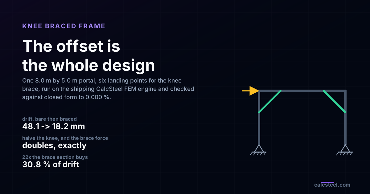
A knee brace is the only diagonal in structural steel whose axis misses the joint on purpose. It lands a distance a down the column and a distance a along the beam, cuts the corner, and leaves the opening clear. That one distance is the whole design: it sets the force in the brace exactly, it sets the drift, and it sets the moment the column is left holding. This article runs an 8.0 m by 5.0 m portal on the shipping CalcSteel FEM engine at six landing points, checks every number against closed form, and ends on a result most engineers do not expect. There is no optimum knee length, and the brace section is almost irrelevant.
Key takeaways
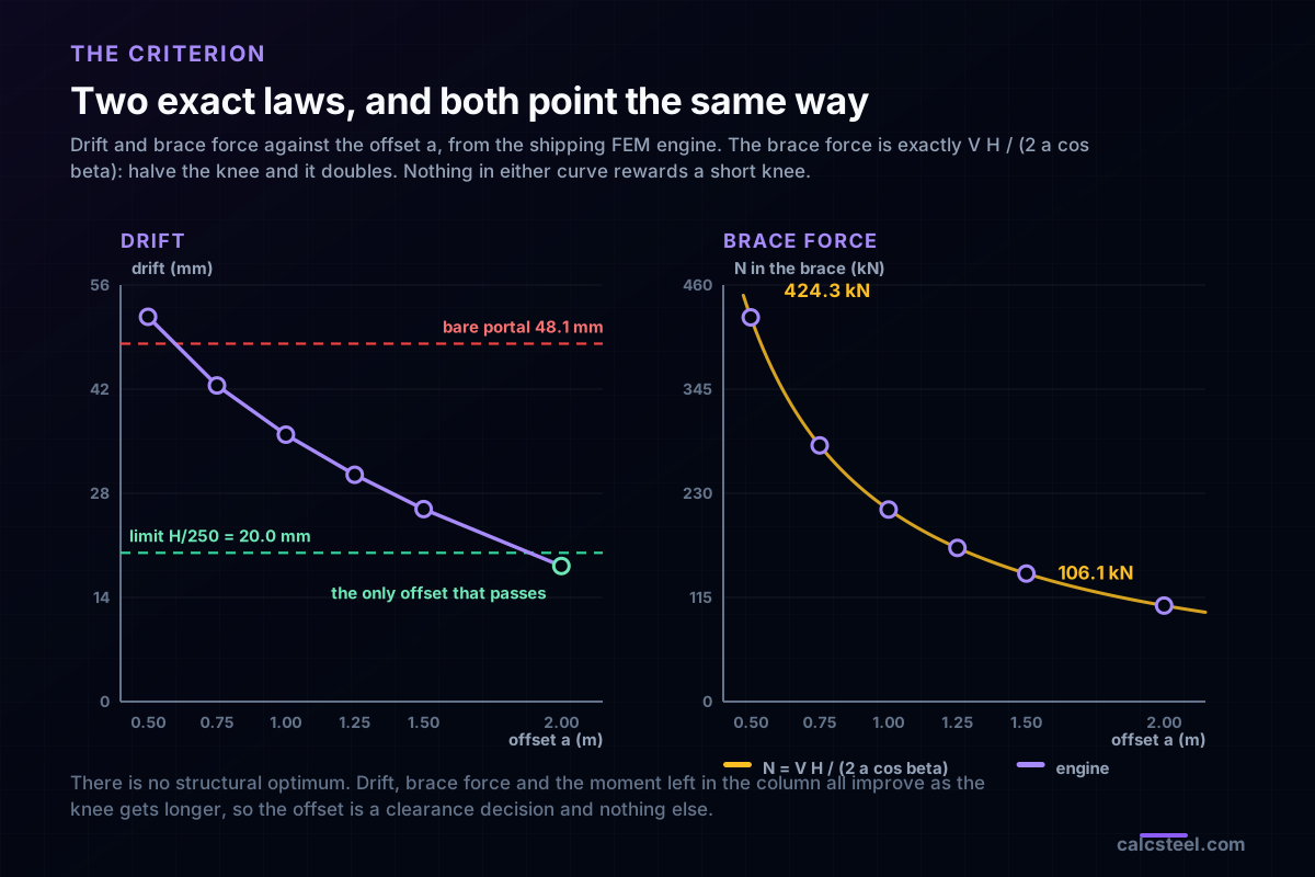
- The criterion is the offset a, and nothing else. The brace force is exactly N = V H / (2 a cos beta): halve the knee and the force doubles. Across the six offsets the engine and that expression agreed to 0.000 %.
- Across the sweep the brace force runs from 424.3 kN at a = 0.5 m to 106.1 kN at a = 2.0 m. A factor of 4 in the member, in the gusset and in the bolt group, decided by where you chose to land the brace.
- Drift moves the same way. The bare portal drifts 48.109 mm, which is H/104 and 140.5 % past an H/250 limit. At a = 0.5 m it drifts 51.728 mm, at a = 2.0 m it drifts 18.236 mm. Only the longest knee passes.
- So there is no structural optimum. Drift, brace force and the moment left in the column all improve as the knee gets longer. The offset is a clearance decision and nothing else, which means the right question is how much corner you can give up.
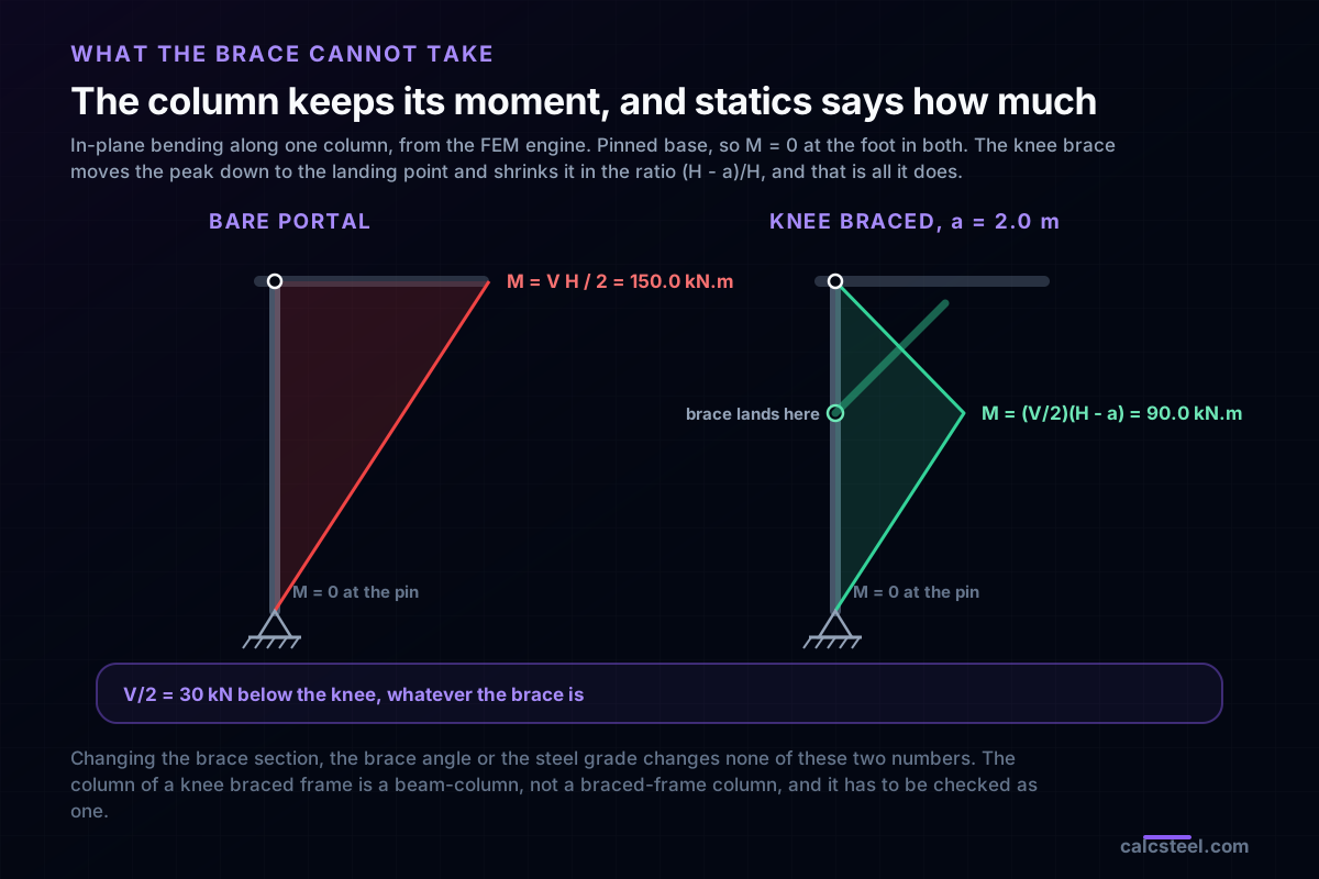
- The moment the column keeps is pure statics: M = (V/2)(H - a) = 90.0 kN.m at the landing point, with a pinned base. The brace section, the brace angle and the steel grade change none of it. A knee braced frame is a moment frame with a spring in it.
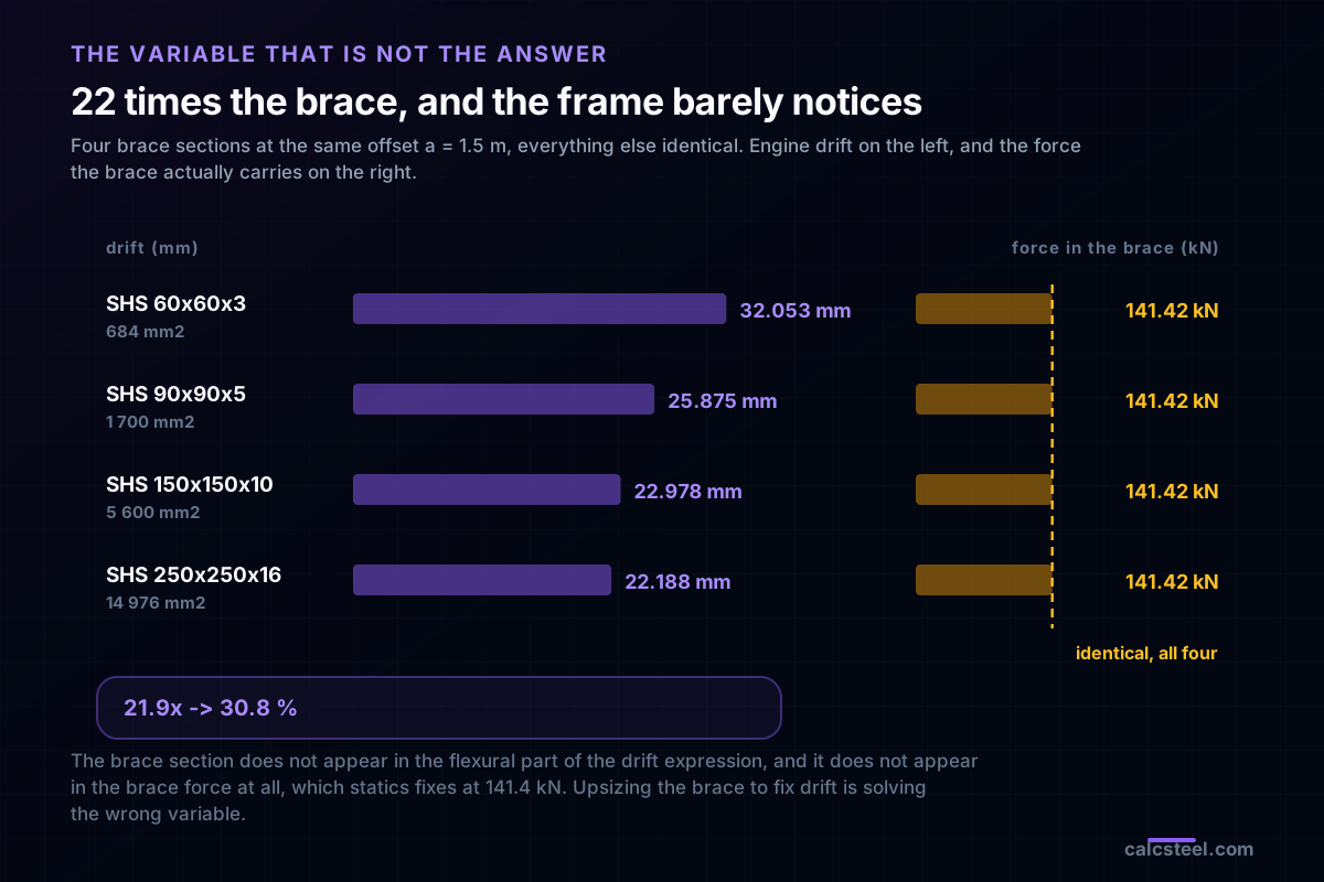
- The brace section is the wrong variable. Twenty-two times the brace area bought 30.8 % of the drift, and 0 % of the brace force, which statics had already fixed at 141.4 kN before any section was chosen.
- A short knee brace can leave the frame softer than no brace at all. At a = 0.5 m the simple frame drifts 51.728 mm against the 48.109 mm of the moment-connected portal, because the brace stretch alone gives back 12.5 mm.
- Once the knee is long enough, the beam-to-column moment connection stops earning its cost: swapping it for a shear connection changed the drift by 1.34 % at a = 2.0 m and by under 1.5 % everywhere above a = 1.0 m.
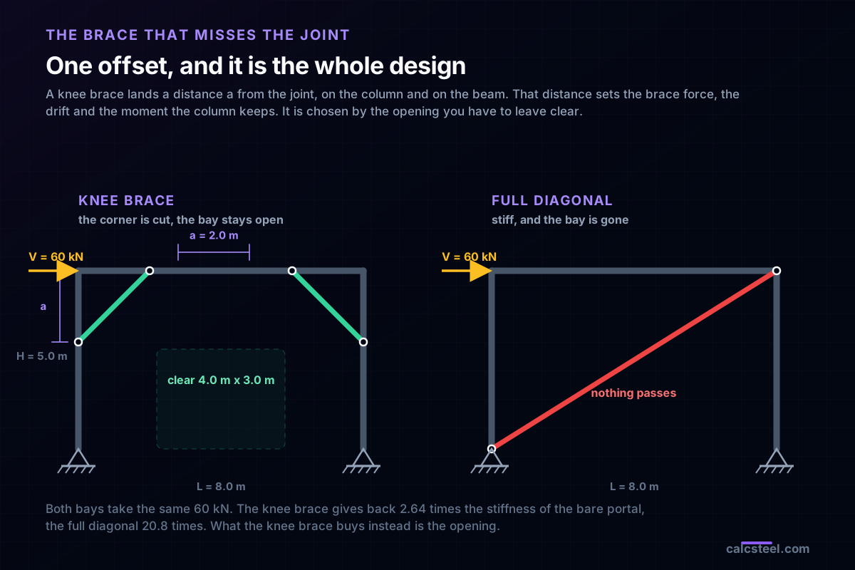
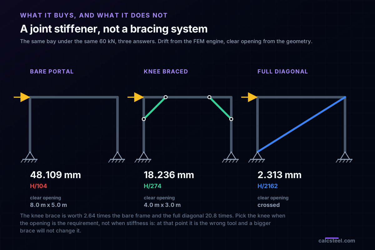
- It is a joint stiffener, not a bracing system. The knee brace bought 2.64 times the stiffness of the bare frame. A full corner-to-corner diagonal of the same SHS bought 20.8 times, and the bay with it.
- Compression is not the question here. At a = 2.0 m the brace is 2.828 m long at KL/r = 81.4, phi Pc = 330.0 kN against a demand of 106.1 kN, a utilisation of 0.321. The tension-only argument that dominates X-bracing does not arise.
- The frame is still a sway frame. The base moment is zero, each base still takes V/2, and alpha cr only moves from 19.49 to 51.41. Design the column as a beam-column, not as a braced-frame column.
The diagonal that misses the joint on purpose
Every other diagonal in structural steel is drawn to a work point. The centrelines of the beam, the column and the brace are made to meet, because when they meet the joint carries force and not moment, and the whole bay can be idealised as a truss. A knee brace does the opposite. It lands a distance a down the column and a distance a along the beam, and it misses the joint deliberately.
It misses it because of what the corner is for. A mezzanine needs the headroom under the beam. A pipe rack needs the pipe to pass. A workshop needs the door. A full diagonal across the bay solves the lateral problem and takes the bay with it. The knee brace cuts the corner instead and leaves the middle open.
What that costs is not obvious, and it is not in most textbooks. Below, an 8.0 m by 5.0 m portal is run on the CalcSteel finite element engine at six different landing points for the knee brace, with everything else held identical. The brace force moves by a factor of 4. The drift moves by a factor of 2.8. And the number that most engineers reach for first, the brace section, turns out to change almost nothing.
What a knee braced frame actually is
A knee braced frame, sometimes written KBF, is a moment-resisting frame with a short diagonal across each beam-to-column corner. The diagonal is usually at 45 degrees, usually the same offset on the column and on the beam, and usually a small tube, angle or channel. You see it on mezzanines, pipe racks, crane gantries, timber portals, canopy frames and light industrial buildings, and it is very old: the same geometry is in medieval timber framing, where it is called a brace or a strut.
Two quite different things are called knee bracing, and they are worth separating before any calculation.
- The stiffener. A knee brace added to stiffen the corner of an ordinary frame under wind, crane surge or notional load. It is a serviceability and stability device. Nothing is meant to yield. This is the common case, and it is what the worked example below is.
- The disposable knee. In seismic design, a knee element is deliberately made the weakest part of the load path so it yields in shear or flexure while the diagonal and the frame stay elastic. The idea traces to Aristizabal-Ochoa's 1986 disposable knee bracing proposal, and the element is meant to be cut out and replaced after an event. It is a cousin of the link in an eccentrically braced frame.
The two share a geometry and almost nothing else. What they do share is the one variable this article is about: the offset.
Braced frame or moment frame? Neither
The first mistake a knee braced frame invites is a classification mistake. There is a brace in the bay, so the frame gets called braced, the columns get an effective length factor of 1.0, the beam-to-column moment is assumed to have gone somewhere, and the second-order check gets skipped.
None of that is true, and the reason is geometric. In a concentrically braced bay the diagonal runs corner to corner, so the horizontal force it carries is delivered straight into the joint and straight down the diagonal to the foundation. The columns are left with axial force. In a knee braced bay the diagonal stops short. Below the landing point the column has no brace at all: it is still a cantilever from the base, and it still carries its share of the story shear in bending.
So the honest classification is a moment frame with a spring across each corner. The spring is stiff and cheap, and it is worth having. It does not convert the frame into anything else, and the numbers below make that quantitative: the base moment stays zero, the column shear below the knee stays at exactly V/2, and the frame's sway amplifier only falls from 1.0541 to 1.0198.
The criterion: two exact laws in the offset
Take one corner. Pinned base, lateral load V at beam level, symmetric bay, so each column takes V/2 of horizontal shear. The knee brace lands at a height H - a on the column and at a distance a along the beam, at an angle beta to the horizontal. Three quantities follow, and two of them are exact statics rather than analysis.
1. The moment left in the column. Below the landing point there is nothing but column. The base is pinned, so the moment grows linearly from zero, and at the landing point it is
Mknee = (V / 2) (H - a)
That expression contains no brace property at all. Not the section, not the angle, not the steel grade, not the stiffness. Whatever you do to the brace, the column keeps that moment.
2. The force in the brace. With simple beam-to-column connections the corner triangle is determinate, and the column above the landing point has to carry Mknee at its bottom and zero at the pin on top, so its shear is Mknee/a. The brace supplies the difference, and it comes out as
Nbrace = V H / (2 a cos beta)
The offset is in the denominator. Halve the knee and the brace force doubles, exactly, and so does everything the brace has to be connected with.
3. The drift. Integrating those two linear moment diagrams by virtual work gives a closed form for the sway of the whole bay:
Δ = V H (H - a)2 / (6 E Ic) + V H2 (L/2 - a)2 / (3 E Ib L) + axial terms
Set a = 0 and it collapses, term by term, onto the bare portal. That is the entire flexural benefit of a knee brace: it replaces H with (H - a) in the column term and L/2 with (L/2 - a) in the beam term. Look at what is not in those two terms. The brace section is not in them. It appears only in the axial terms, which are small.
All three point the same way. Longer knee, less force, less drift, less moment left in the column. There is no structural optimum to find. The offset is chosen by the opening you have to leave clear, and by nothing else.
The bay that is worked below
A storage mezzanine portal, which is where knee braces earn their living.
- Span L = 8.0 m column centre to column centre, height H = 5.0 m base to beam axis, pinned bases.
- Columns HEB 300 (Ix = 24 480.5 cm4), beam IPE 400 (Ix = 22 222.4 cm4), knee braces SHS 90x90x5 (A = 1 700 mm2, r = 34.76 mm). Steel S355, E = 200 GPa.
- Equal offsets on the column and the beam, so every brace is at 45 degrees and its length is a times the square root of 2.
- Lateral load V = 60 kN at beam level, 30 kN at each top node. Factored gravity on the beam 40 kN/m, which is 320 kN on the frame.
- Serviceability limit H/250 = 20.0 mm, the usual order for a clad industrial frame. Your national annex may say H/300 or H/150; the arithmetic below does not change, only which row passes.
Two modelling points, because they decide whether the numbers mean anything. First, the columns and the beam are continuous through the landing points. That is not a refinement, it is the structure: a knee brace cannot work in a fully pin-jointed frame, because the assembly would be a mechanism. Second, the primary models use simple beam-to-column connections, which is the real detail on a mezzanine, and it makes the corner determinate so that every station is a hand check. The rigid-joint version was run alongside, and the comparison is in its own section below.
Everything is run on app.engine.solver.run_analysis, the same engine behind the CalcSteel editor, and every published number is checked against closed form before it appears here.
Step 1: the bare portal, and why anyone reaches for a knee brace
Before the brace, the frame on its own. A pinned-base portal with moment connections at both corners is a perfectly respectable structure. It is also soft, and slope deflection says how soft. Writing the joint equilibrium with the sway term and the shear equation 2 Mtop / H = V gives
Δ = V H2 L / (12 E Ib) + V H3 / (6 E Ic)
which for this bay is 22.50 mm from the beam plus 25.53 mm from the columns, 48.03 mm in total. The engine returned 48.109 mm, a difference of 0.16 %, and the 0.16 % is the columns shortening axially under the overturning couple, which the closed form ignores.
48.109 mm is H/104. Against an H/250 limit it is over by 140.5 %. The frame is not close, and no reasonable adjustment of the sections fixes it: the column term goes as H cubed, so buying it back in section means a very large column.
The column moment at the top is 150.0 kN.m, which is V H / 2 exactly, and the engine returned exactly that. Hold on to the number. It is what the knee brace is about to be judged against.
Step 2: six landing points, one passes
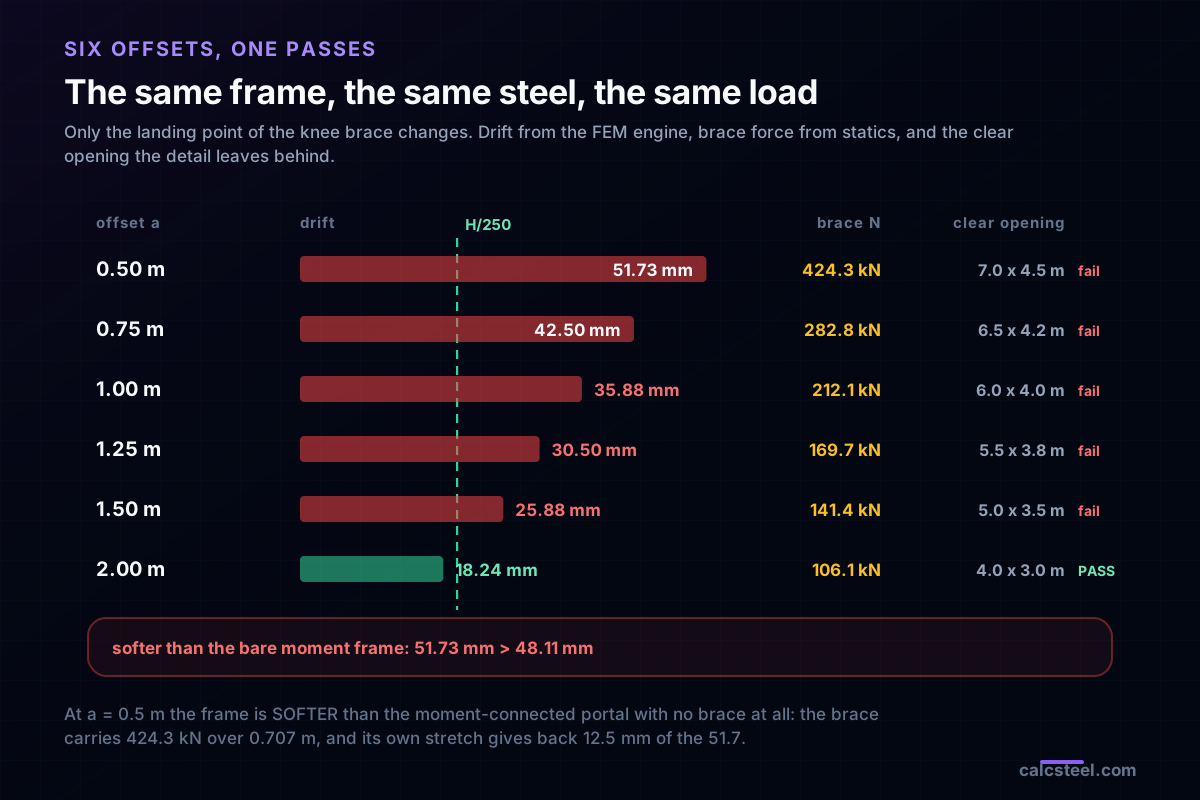
Now the knee braces go in, same SHS 90x90x5 in every run, and only the landing point changes. Six offsets from 0.5 m to 2.0 m. The drift column is the FEM engine; the brace force column is the engine as well, and it landed on V H / (2 a cos beta) to 0.000 % in all six runs.
| offset a | brace length | drift | ratio | N in the brace | M at the knee | clear opening | H/250 |
|---|---|---|---|---|---|---|---|
| 0.50 m | 0.707 m | 51.728 mm | H/97 | 424.3 kN | 135.0 kN.m | 7.0 x 4.5 m | fail |
| 0.75 m | 1.061 m | 42.498 mm | H/118 | 282.8 kN | 127.5 kN.m | 6.5 x 4.25 m | fail |
| 1.00 m | 1.414 m | 35.883 mm | H/139 | 212.1 kN | 120.0 kN.m | 6.0 x 4.0 m | fail |
| 1.25 m | 1.768 m | 30.496 mm | H/164 | 169.7 kN | 112.5 kN.m | 5.5 x 3.75 m | fail |
| 1.50 m | 2.121 m | 25.875 mm | H/193 | 141.4 kN | 105.0 kN.m | 5.0 x 3.5 m | fail |
| 2.00 m | 2.828 m | 18.236 mm | H/274 | 106.1 kN | 90.0 kN.m | 4.0 x 3.0 m | pass |
Three things in that table are worth stopping on.
Only the longest knee passes, and it passes with 8.8 % to spare. Everything shorter fails the limit, some of them badly. A knee brace is not a token: it either takes a serious bite out of the corner or it does not do much.
The brace force is exactly inverse in the offset. 424.3 kN at 0.5 m against 106.1 kN at 2.0 m is a factor of 4 on a factor of 4 in the offset. That factor is not just in the member. It is in the gusset, in the bolt group, in the weld and in the local check of the column web where the brace lands.
The 0.5 m row is softer than having no brace at all. 51.728 mm against the 48.109 mm of the moment-connected bare portal. Give up the moment connection for a short knee brace and you have traded down. The reason is in the closed form: the brace carries 424.3 kN over 0.707 m, and its own axial stretch contributes 12.5 mm of the 51.7 mm.
Step 3: checking the brace that the offset handed you
Take the row that passes, a = 2.0 m. The brace is 2.828 m of SHS 90x90x5 carrying 106.07 kN, and the first thing to notice is that the number came out of statics before any section existed. You do not size a knee brace and then find its force. The geometry fixes the force, and the section only has to survive it.
Compression governs on the leeward corner. With r = 34.76 mm and K = 1.0 over the full brace length:
- KL/r = 2 828 / 34.76 = 81.4, comfortably inside the 200 that AISC recommends for compression members.
- Fe = pi squared E / (KL/r) squared, and AISC 360 E3 then gives phi Pc = 330.0 kN.
- Demand over capacity = 106.07 / 330.0 = 0.321. It passes with room.
In tension the same section has phi Pt = 543.1 kN on the gross section, a utilisation of 0.195.
That low utilisation is characteristic and it matters. A knee brace is short, so compression is almost never the question. The tension-only argument that dominates cross bracing, where one diagonal is written off because it buckles at KL/r of 200 or more, simply does not arise here. Run the load the other way and the engine hands the mirror brace the same 106.07 kN. Both knee braces work, in both directions, always.
Two equilibrium checks worth doing on your own model, because they catch a wrongly released end immediately. At the landing point on the column, the brace's horizontal component is 75.0 kN, and the engine reports the column's axial force jumping by 75.0 kN and its shear jumping by 75.0 kN across that same node. And the beam segment between the landing point and the column picks up 75.0 kN of axial compression, which is the same component again. If those three numbers are not equal in your model, the brace is not doing what the drawing says.
Run the bare portal yourself
The bare portal is the half of this problem you can reproduce in a minute. Put in the 8.0 m span, the 5.0 m height, the sections and the 60 kN, and read the drift and the base reactions off a real 2D frame solve. The knee-braced numbers then follow from the closed form in the criterion section above.
Diagrams plotted on the deformed-free frame geometry. N, V, M recovered from the element end-forces of the direct-stiffness solve (12 elements / member). Moment drawn offset to each member's centreline.
First-order STRENGTH screening at the governing section of the NBR 8800 (BR) ULS envelope (governing CB2): N,d = 73.9 kN, M,d = 109 kN·m. Member buckling and lateral-torsional buckling are NOT included — see the stability flags below and run the full verification in the 3D editor. Click a card to make that resistance code govern the ranking.
ULS load combinations — NBR 8800 (BR)
G + W superposed · 3 combinations| Combination | Factors | Utilization |
|---|---|---|
| CB1 | 1.4 G | 69% |
| CB2governs | 1.4 G + 1.4 W | 76% |
| CB3 | 1 G + 1.4 W | 57% |
Combinations generated by the CalcSteel combinations engine (the same v4 engine the 3D editor uses, 6 codes). Gravity is treated as a single permanent action G; the wind action W is the eaves load. Each combination's γ factors are applied by superposition to the isolated gravity and wind solves, then every section is screened — the worst point of the worst combination governs.
Stability screening (buckling caveats)
not in the strength checkScreening indicators only — assumed sway effective length (K = 1.5) and the full member length as the unbraced length (no intermediate purlin/girt restraint). The strength check above deliberately excludes these; the real member verification (effective lengths from the alignment chart / notional loads, χ and Cb reduction factors, purlin bracing) runs in the 3D editor.
Lightest sections that pass (NBR)
screened 974 profiles| Profile | Mass | Frame steel | Utilization | |
|---|---|---|---|---|
| VS 400x32 | 31.9 kg/m | 723 kg | 82% | |
| VS 350x33 | 33.2 kg/m | 752 kg | 86% | |
| VS 400x34 | 34.4 kg/m | 779 kg | 75% | |
| VS 350x35 | 35.1 kg/m | 795 kg | 80% | |
| VS 400x35 | 35.1 kg/m | 795 kg | 73% |
What the brace cannot take away
Here is the result that decides how you check the column, and it is the one the braced-frame classification gets wrong.
In the bare portal the column's in-plane moment grows from zero at the pinned base to 150.0 kN.m at the top. In the knee-braced frame it grows from zero at the pinned base to 90.0 kN.m at the landing point, then falls away above it. That 90.0 is (V/2)(H - a) = 30 x 3.0, and the engine returned it to the second decimal.
So the brace did two things: it moved the peak down to the landing point, and it shrank it in the ratio (H - a)/H, which here is 3.0/5.0 = 0.6. It did not remove it, and nothing you do to the brace will. Below the landing point the column still carries V/2 = 30 kN of shear, and 30 kN of shear over 3.0 m of cantilever is 90 kN.m whether the brace above is a tube, a channel, a rod or a rolled section.
Check the column accordingly. For this frame the axial force is 160.0 kN per column against phi Pc = 3 431 kN, and the moment is 90.0 kN.m against phi Mp = 599.5 kN.m, so the AISC 360 H1-1 interaction ratio is 0.1735 with the knee braces against 0.2735 without: 36.6 % of relief. Real, welcome and finite. The column of a knee braced frame is a beam-column and has to be checked as one.
The variable that is not the answer: the brace section
A frame fails drift. The instinct is to upsize the brace. Here is what that buys, with the offset held at a = 1.5 m and everything else identical.
| brace section | area | drift | force in the brace |
|---|---|---|---|
| SHS 60x60x3 | 684 mm2 | 32.053 mm | 141.42 kN |
| SHS 90x90x5 | 1 700 mm2 | 25.875 mm | 141.42 kN |
| SHS 150x150x10 | 5 600 mm2 | 22.978 mm | 141.42 kN |
| SHS 250x250x16 | 14 976 mm2 | 22.188 mm | 141.42 kN |
21.9 times the area bought 30.8 % of the drift, and going from the 90x90x5 to the 250x250x16, an 8.8-fold jump in steel, bought 14.2 %. The curve is flat and it was always going to be flat, because the brace section does not appear in the flexural part of the drift expression. It appears only in one axial term, and by the third row that term has been squeezed close to zero. Beyond that the frame's own bending is all that is left.
And look at the last column. The force in the brace does not move at all. 141.42 kN in every row, because statics fixed it from the geometry before any section was chosen. Upsizing a knee brace does not relieve the knee brace. It only lowers its utilisation, which was not the problem.
If the frame is too soft, the variables that actually work are, in order: the offset, the column section, the beam section, and fixing the bases. The brace section is fourth or fifth on that list, and it is the one everyone tries first.
What a knee brace buys, and what it does not
Three versions of the same bay under the same 60 kN, and the comparison that should be made before the detail is chosen.
- Bare portal: 48.109 mm, H/104, clear opening 8.0 m by 5.0 m.
- Knee braced at a = 2.0 m: 18.236 mm, H/274, 2.64 times the stiffness, clear opening 4.0 m by 3.0 m.
- Full corner-to-corner diagonal, same SHS 90x90x5: 2.313 mm, H/2162, 20.8 times the stiffness, and the bay is crossed.
A factor of 2.6 against a factor of 21. That gap is the honest summary of what a knee brace is. It is a joint stiffener, not a bracing system. Choose it when the clear opening is the requirement. Do not choose it when stiffness is the requirement, because then it is the wrong tool, and the saturation table above says a bigger brace will not rescue it.
One caveat on that diagonal, in fairness to it. At 9.434 m and KL/r = 271, the same SHS in compression over the full length has phi Pc = 36.0 kN against the 67.4 kN the engine puts through it, so a single full-length diagonal of that section is a tension-only member and you would pair it into an X. That is a different design decision with its own criterion, and it is the subject of its own article.
It is still a sway frame, and the code still says so
The classification matters because two code checks hang off it.
Second-order effects. EN 1993-1-1 clause 5.2.1(3) lets you use first-order analysis when alphacr = (HEd/VEd) (h/δH) is at least 10. For this frame the lateral stiffness goes from 1 247.2 kN/m bare to 3 290.2 kN/m knee braced, so under the 320 kN of factored gravity alphacr moves from 19.49 to 51.41. The AISC 360 story amplifier B2 moves from 1.0541 to 1.0198 over the same change. Both pass either way here, which is itself worth saying plainly: for a mezzanine portal it is the serviceability limit that bites, not the stability trigger. But the amplifier is above 1.0 in both cases, because the frame sways in both cases.
Column effective length. A knee braced frame is not a braced frame for buckling. The base moment is zero, the base shear is still V/2, and the sway mode is still there. Taking K = 1.0 because there is a brace in the picture is not conservative. Use the direct analysis method, or a sway K from the story stiffness, and let the frame's own drift set the answer.
One more number on the same theme. Swapping the beam-to-column moment connections for shear connections changed the drift by 1.34 % at a = 2.0 m, and by under 1.5 % at every offset from 1.0 m up. Once the knee is long enough, the moment connection has almost stopped earning its cost, which is exactly why the simple-frame-plus-knee-braces detail exists. Below 1.0 m the comparison inverts and the moment connection is worth 13 %, so the substitution is only safe once the knee is long.
Detailing, and the seismic version
The connection is the expensive half. The brace force is fixed by geometry, so the shorter the knee the heavier every part of the connection. At a = 0.5 m the gusset, bolts and welds have to carry 424.3 kN; at a = 2.0 m they carry 106.1 kN. Size the connection for the force the offset gives you, and check the local effects where the brace lands: web crippling and panel-zone shear on the column, and web crippling on the beam, since neither landing point is a stiffened joint by default.
The beam is now a compression member too. In the worked bay the end segment of the beam carries 75.0 kN of axial compression, and the beam carries an in-plane moment of 75.0 kN.m at the landing point on top of its gravity bending. Combine them; do not check the beam for gravity alone.
Out-of-plane restraint. The knee brace is an in-plane member and does nothing about the column's minor axis. That still needs the usual side rails, floor diaphragm or plan bracing.
The seismic version. Where a knee braced frame is used as a ductile system, the hierarchy inverts: the knee element is made the fuse and has to yield first, so the diagonal and its connections are designed for the over-strength force the yielding knee can deliver, not for the elastic demand. That is the same capacity-design logic Eurocode 8 applies to the link of an eccentrically braced frame. It also means the two design problems are opposite: in the stiffener case you want the knee strong, in the fuse case you want it exactly weak enough. Decide which one you are building before you size anything, and check your national seismic provisions, because knee braced frames are not a listed system in every code and may not carry a tabulated response modification factor.
Six ways this goes wrong
- Calling it a braced frame. The column below the landing point has no brace on it. It keeps (V/2)(H - a) of moment and it keeps its sway mode. Check it as a beam-column.
- Upsizing the brace to fix drift. 21.9 times the area bought 30.8 % of the drift and 0 % of the brace force. The offset, the column and the base fixity are the variables that move the answer.
- Modelling the knee brace in a pin-jointed frame. It cannot work there. A knee brace needs flexural continuity in the column and the beam through the landing points; a fully pin-jointed version of the same geometry is a mechanism.
- A token knee brace. At a = 0.5 m the frame was softer than the moment-connected portal with no brace at all, 51.728 mm against 48.109 mm. A short knee brace is not a cheap version of a long one; it can be worse than nothing.
- Sizing the connection from the member, not the geometry. The brace force is V H / (2 a cos beta) whatever section you put there. A connection detailed from a light brace's capacity can be a long way under the force the frame will actually deliver.
- Forgetting the beam. The beam end segment took 75.0 kN of axial and 75.0 kN.m of moment from the brace in the worked bay, on top of gravity. A beam checked for gravity alone has been checked for the wrong structure.
The check, in order
- Fix the offset from the clearance, not from the structure. Take the longest knee the opening tolerates. Every structural quantity improves with it.
- Get the brace force from geometry: N = V H / (2 a cos beta). It does not depend on what you put there.
- Check the brace in compression over its full length, and in tension. It will usually be lightly used; that is normal.
- Check the column as a beam-column for (V/2)(H - a) plus its gravity axial. The brace does not take this moment away.
- Check the beam for its gravity moment combined with the axial and the local moment the brace delivers at the landing point.
- Check the drift against your limit, with the frame's real stiffness. If it fails, go back to step 1, then to the column section, then to the bases. Do not go to the brace section.
- Check stability: alphacr or B2, with the frame treated as a sway frame, because it is one.
- Detail the connection for the geometric force, and check web crippling and panel-zone shear at both landing points.
- If the answer is that you need real stiffness, and the opening will allow it, stop and put a full diagonal in. The knee brace was worth 2.64 times; the diagonal was worth 20.8.
Sources
- 1.ANSI/AISC 360, Specification for Structural Steel Buildings: Chapter E for compression (the E3 flexural buckling equations used for the brace), Chapter D for tension, Chapter H for the beam-column interaction, and Appendix 7 for the story stiffness and the B2 amplifier
- 2.ANSI/AISC 341, Seismic Provisions for Structural Steel Buildings: the capacity-design logic that makes a designated yielding element the fuse and sizes everything around it for the force that element can deliver
- 3.EN 1993-1-1, Eurocode 3, design of steel structures, general rules: clause 5.2.1(3), which allows first-order analysis when alpha cr is at least 10, and Section 6.3 for the buckling reduction factor
- 4.EN 1998-1, Eurocode 8, design of structures for earthquake resistance: clause 6.8 on frames with eccentric bracings, the closest listed relative of a ductile knee braced frame, where a designated link yields and the rest of the frame is capacity-designed around it
- 5.ABNT NBR 8800, Projeto de estruturas de aco e de estruturas mistas de aco e concreto: the compression and beam-column provisions, and Annex C Table C.1, which limits the horizontal displacement of the top of the columns relative to the base to H/400
- 6.J. D. Aristizabal-Ochoa, Disposable Knee Bracing: Improvement in Seismic Design of Steel Frames, ASCE Journal of Structural Engineering, 1986: the original proposal for the knee element as a replaceable ductile fuse
- 7.T. Balendra, M. T. Sam and C. Y. Liaw, Diagonal Brace with Ductile Knee Anchor for Aseismic Steel Frame, Earthquake Engineering and Structural Dynamics, 1990: the experimental work behind the knee-anchored braced frame
- 8.ASCE 7, Minimum Design Loads and Associated Criteria for Buildings and Other Structures: the non-mandatory appendix on serviceability, which suggests drift limits of the order of 1/600 to 1/400 of the building or story height
Try CalcSteel for free
Model, analyze and design steel structures in your browser. No install, no signup.
Open the 3D editor