Shear Wall Bracing: the Shear, Overturning and Drift Criterion Behind the Code
A shear wall is not a wall you add braces to. The wall is the brace: it takes the lateral load in its own plane and walks it down to the foundation, which is exactly what a diagonal-braced bay does with steel instead of concrete. That is why the code never writes a shear wall as one check. It writes three, and they act at the same time: the in-plane shear the panel must pass, the overturning couple that loads the two boundary chords and their hold-downs, and the drift. Which of the three governs is decided by one number you set the day you place the wall, the aspect ratio h over the wall length. This guide derives that criterion, then runs the real CalcSteel engine on a 4.0 m by 4.0 m wall and on a squat-to-slender sweep to show the same 200 kN story shear producing four times the chord force and five times the drift as the wall slims down.
Key takeaways
- A shear wall is the bracing, not something you brace. It resists the lateral load in its own plane, so shear wall bracing is a lateral-force-resisting system, the concrete or plate equivalent of a braced steel bay, not an extra member bolted to a wall.
- The criterion behind the code is three limit states at once, not one: the in-plane shear the panel passes to the foundation, the overturning couple that puts T = C = M/Lw into the two chords with a hold-down against uplift, and the story drift. A wall passes all three or fails on the one you did not check.
- The aspect ratio h/Lw decides which limit governs. On the CalcSteel engine the same 200 kN story shear gives a squat wall, h/Lw = 0.5, a 99 kN chord and 1.65 mm of drift, and a slender wall, h/Lw = 2.0, a 391 kN chord and 7.90 mm of drift: four times the chord force, roughly five times the drift, for the identical shear.
- On the worked 4.0 m by 4.0 m wall the engine returns 278.8 kN in the shear path and 197.4 kN in the leeward chord, confirming the hand values V/cos theta = 282.8 kN and M/Lw = 200 kN. The hold-down still has to carry 119 kN of net uplift, and the drift comes out at 2.35 mm, a comfortable h/1695.
- If the wall is a steel plate shear wall, the 3 mm web passes the story shear at only 18 percent of its 1134 kN strength. The plate is rarely the limit. The boundary elements that carry the overturning and the drift are what govern, which is why a steel shear wall is designed from the chords in, not the web out.
What shear wall bracing actually means
The phrase trips people up because it reads like two systems. It is one. A shear wall is a bracing element: a stiff vertical panel that receives the lateral load a floor delivers to it and carries that load down to the foundation by acting in shear along its own plane. It is the wall that keeps the building from racking sideways in a wind gust or an earthquake. When an engineer says a bay is shear-wall braced, they mean the lateral system in that bay is a wall panel rather than a diagonal, a moment frame, or a core.
For a steel building the point is worth pressing, because a shear wall and an X-braced bay do the same job by the same mechanics. Both are vertical cantilevers rooted at the base. Both convert a horizontal story force at the top into an axial couple at the bottom. The concrete or the steel plate simply spreads the diagonal compression and tension fields across a continuous panel instead of concentrating them in one member. So everything you know about designing a brace, resolve the shear along the diagonal, chase the overturning into the chords, watch the drift, carries straight over to a shear wall. What changes is only that the wall does all three jobs in one piece.
Shear wall vs braced frame vs moment frame
Three systems can brace a bay against lateral load, and they trade the same three currencies: stiffness, ductility, and the space they leave you.
- Shear wall. The stiffest of the three. A solid panel draws lateral load to itself precisely because it is stiff, so it attracts a large share of the story shear and keeps drift small. The cost is that it is a wall: it blocks the bay, and its overturning has to be anchored hard into the foundation.
- Braced frame. A diagonal or an X in a steel bay. Nearly as stiff as a wall for a fraction of the weight, and it leaves the bay open above and below the diagonal. It is the direct steel cousin of the shear wall, and the worked check below models the wall as exactly this, an equivalent braced bay.
- Moment frame. No diagonal and no wall, just rigid beam-to-column joints. It leaves the bay completely open, which architects love, but it is far more flexible, so drift, not strength, usually sizes it.
The reason a shear wall gets its own design conversation is that its stiffness is a double-edged tool. It pulls in load, which is why it protects the rest of the frame, and that same pulled-in load is a large overturning moment it then has to shed into two chords and a foundation. Stiffness in, overturning out. Keep that trade in mind and the code criterion writes itself.
The three jobs a shear wall does, not one
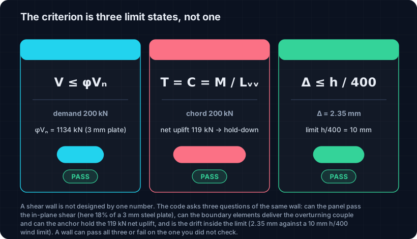
Open any code chapter on shear walls and you find not a single equation but a short list. That is the whole idea. The same wall, under the same story shear, has to satisfy three independent limit states, and they do not rise or fall together:
- In-plane shear. The panel has to pass the story shear V through itself without the web crushing, tearing, or buckling. This is the unit shear v = V/Lw smeared along the wall length.
- Overturning. A horizontal force applied high on a vertical wall is a moment at the base, M = V times h. That moment is resolved into a tension chord on the windward edge and a compression chord on the leeward edge, T = C = M/Lw, and the tension chord has to be held down against uplift.
- Drift. Even a wall that is strong enough can be too flexible. The sideways movement at the top, the drift, has to stay inside a serviceability limit so finishes do not crack and occupants do not feel the sway.
Miss any one and the wall fails on the axis you did not look at. A wall can have ample shear strength and still tear its hold-down out of the footing, or hold its ground on strength and still drift past the limit. The figure lays the three side by side for the worked wall so you can see they are separate questions with separate answers.
The criterion behind the code, from first principles
Start with equilibrium and let the wall be a cantilever standing on its base. A story shear V arrives at the top over a height h. Nothing else is needed to write all three demands.
Shear. The horizontal force has to cross every horizontal cut in the wall, so the shear demand is simply V, and per unit of wall length it is
v = V / Lw
Overturning. That same V, applied a height h above the base, makes a moment M = V h that tries to tip the wall over its leeward toe. A rigid panel resists it the way a beam cross section resists bending: plane sections stay plane, so the resistance is a couple of two edge forces separated by the wall length. Setting the resisting couple equal to the applied moment,
T = C = M / Lw = V h / Lw
One edge goes into tension, the other into compression, equal and opposite. The compression chord leans on the concrete or the column below it. The tension chord has nothing to lean on but the anchor, so it needs a hold-down sized for the net uplift after the wall's own dead load is credited.
Drift. Flexibility is the third axis. The top of the wall moves sideways by an amount that grows with the cube of its height for the flexural part and linearly for the shear part, and the code caps it, commonly at h/400 for wind serviceability or a multiple of that for seismic. Strength does not bound drift, stiffness does, which is why it is a separate check.
Look at the overturning equation and the criterion behind the code is already visible: T and C carry h in the numerator and Lw in the denominator. The wall's proportions, not just its loads, set the chord force. That is the ratio the next section puts numbers on.
The aspect ratio decides which one governs
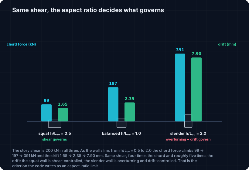
Hold the story shear fixed at 200 kN and change only the shape of the wall. A squat wall, wide and short, is nearly all shear panel: the overturning arm h is small, so the chord force is small and the thing barely moves. A slender wall, narrow and tall, is nearly all cantilever: the arm h is large and the lever Lw is short, so the same story shear becomes a large chord force and a large drift. The governing limit state migrates from shear to overturning-and-drift as the wall slims, and it does so fast.
The CalcSteel engine makes the migration concrete. Modeling each wall as its equivalent braced bay and pushing the identical 200 kN across the top:
- Squat, h/Lw = 0.5 (6.0 m by 3.0 m): leeward chord 99 kN, drift 1.65 mm, about h/1818. Shear governs; overturning and drift are almost free.
- Balanced, h/Lw = 1.0 (4.0 m by 4.0 m): chord 197 kN, drift 2.35 mm, about h/1695.
- Slender, h/Lw = 2.0 (3.0 m by 6.0 m): chord 391 kN, drift 7.90 mm, about h/758. Overturning and drift now govern.
Read the ends against each other. The story shear never changed, yet the chord force went from 99 to 391 kN, almost exactly four times, and the drift from 1.65 to 7.90 mm, roughly five times. This is why codes cap a wall's height-to-length ratio and treat slender walls as flexure-controlled: past a certain slenderness the wall stops being a shear panel and becomes a tall cantilever whose chords and anchors, not its web, decide the design.
Worked check, part 1: the in-plane shear
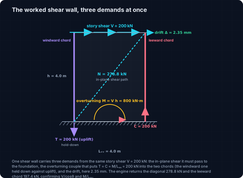
Take the balanced wall forward as the full worked example: Lw = 4.0 m, h = 4.0 m, a factored story shear V = 200 kN delivered by the diaphragm at roof level. Modeled as an equivalent braced bay, the wall's in-plane shear travels down the diagonal at 45 degrees, so the hand value for the diagonal axial force is
N = V / cos theta = 200 / cos 45 = 282.8 kN
Run the same model on the CalcSteel engine and it returns 278.8 kN in the diagonal. The small gap from 282.8 kN is real, not error: the frame shares a sliver of the shear through the columns and the joint, so the diagonal carries slightly less than the pin-truss idealization predicts. Within a percent and a half, the engine confirms the hand check.
Now the capacity side, and here the steel form of the wall is instructive. If the panel is a 3 mm steel plate web spanning the 4.0 m between boundary columns, its in-plane shear strength by the AISC plate-wall provision is phi Vn = 0.42 Fy tw Lcf, which for a mild web comes to 1134 kN. The 200 kN demand uses only 18 percent of it. The lesson repeats across nearly every real shear wall: the panel itself has shear strength to spare. What sizes the wall is what happens at its edges and how far it moves, which are parts two and three.
Worked check, part 2: overturning and the hold-down
The 200 kN story shear sits 4.0 m above the base, so the overturning moment is
M = V h = 200 times 4.0 = 800 kN m
Resolved into the chord couple over the 4.0 m wall length, that is T = C = M/Lw = 800/4.0 = 200 kN of tension on the windward edge and 200 kN of compression on the leeward edge. The engine corroborates the couple directly: it returns the leeward chord at 197.4 kN of compression, matching M/Lw once the small frame share is accounted for, and the windward edge carries the equal-and-opposite tension.
The compression chord is the easy one; it leans on the material below it. The tension chord is where shear walls are lost. That 200 kN of uplift has to be delivered into the foundation through a hold-down, and only the wall's own weight helps resist it. Credit the factored-down dead load tributary to that chord, say 0.9 times a 90 kN dead reaction, and the anchor still has to carry
net uplift = 200 minus 0.9 times 90 = 119 kN
That 119 kN is a real hold-down, a real embedment, and a real load path all the way to a footing heavy enough not to lift. On the three-criteria figure this is the middle panel, and it is the one flagged anchor-governs for a reason: for most walls of ordinary proportion, the overturning anchorage, not the panel shear, is the check that sizes the design and the one most often detailed short.
Worked check, part 3: the drift
Strength satisfied twice over, the wall still has to be stiff enough. The engine reports the top of the 4.0 m by 4.0 m wall moving 2.35 mm under the 200 kN shear. Compared against a common wind serviceability cap of h/400,
h/400 = 4000/400 = 10 mm, and 2.35 mm is h/1695
so the balanced wall clears the drift limit with a factor of more than four in hand. That comfort is a direct consequence of the aspect ratio. Go back to the sweep: the slender wall at h/Lw = 2.0 drifts 7.90 mm, still inside 10 mm but now only h/758, and a slightly taller or narrower wall would breach it while its shear strength sat almost untouched. Drift is the limit that closes in on you as the wall grows slender, silently, because it never shows up as an overstress, only as a number creeping toward the cap.
That is the whole reason drift is a separate criterion and not a footnote to strength. A wall can be twice as strong as it needs to be and still fail serviceability, and no amount of extra plate thickness fixes it, because plate thickness buys shear strength, not stiffness against overturning rotation. Stiffness against drift comes from the chords and the wall length, the same two things that set the overturning force.
See it yourself: push the wall and watch the drift
The migration from shear-controlled to drift-controlled is easier felt than read. The embedded calculator models a single-bay frame the way the worked wall was modeled: put a lateral force across the top, then change the bay width and height and watch two numbers move together, the axial force in the members and the sideways drift. Widen the bay and both fall. Raise it and both climb, the drift faster than the force. That divergence, force creeping up while drift races up, is the aspect-ratio criterion of this whole article, live and in your hands.
Reproduce the worked wall first, a 4.0 m bay under 200 kN, and you will see the drift land near the couple of millimetres the engine reported. Then slim it toward h/Lw = 2 and watch the drift approach and pass the point where serviceability, not strength, is the wall you hit.
Diagrams plotted on the deformed-free frame geometry. N, V, M recovered from the element end-forces of the direct-stiffness solve (12 elements / member). Moment drawn offset to each member's centreline.
First-order STRENGTH screening at the governing section of the NBR 8800 (BR) ULS envelope (governing CB2): N,d = 73.9 kN, M,d = 109 kN·m. Member buckling and lateral-torsional buckling are NOT included — see the stability flags below and run the full verification in the 3D editor. Click a card to make that resistance code govern the ranking.
ULS load combinations — NBR 8800 (BR)
G + W superposed · 3 combinations| Combination | Factors | Utilization |
|---|---|---|
| CB1 | 1.4 G | 69% |
| CB2governs | 1.4 G + 1.4 W | 76% |
| CB3 | 1 G + 1.4 W | 57% |
Combinations generated by the CalcSteel combinations engine (the same v4 engine the 3D editor uses, 6 codes). Gravity is treated as a single permanent action G; the wind action W is the eaves load. Each combination's γ factors are applied by superposition to the isolated gravity and wind solves, then every section is screened — the worst point of the worst combination governs.
Stability screening (buckling caveats)
not in the strength checkScreening indicators only — assumed sway effective length (K = 1.5) and the full member length as the unbraced length (no intermediate purlin/girt restraint). The strength check above deliberately excludes these; the real member verification (effective lengths from the alignment chart / notional loads, χ and Cb reduction factors, purlin bracing) runs in the 3D editor.
Lightest sections that pass (NBR)
screened 974 profiles| Profile | Mass | Frame steel | Utilization | |
|---|---|---|---|---|
| VS 400x32 | 31.9 kg/m | 723 kg | 82% | |
| VS 350x33 | 33.2 kg/m | 752 kg | 86% | |
| VS 400x34 | 34.4 kg/m | 779 kg | 75% | |
| VS 350x35 | 35.1 kg/m | 795 kg | 80% | |
| VS 400x35 | 35.1 kg/m | 795 kg | 73% |
Where the demand comes from: wind and seismic story shear
Every number above started from a 200 kN story shear, so it is worth saying where that value is born, because the two lateral loads that produce it behave differently and one of them interacts with the wall's own stiffness.
Wind is a pressure on the building face. The diaphragm at each floor collects the tributary wind pressure over the story and drags it into the shear walls in that line. Wind does not care how stiff the wall is; the force is set by exposure, height, and shape, and the wall simply has to take its share.
Seismic is an inertial force, mass times acceleration, and here the wall's stiffness bites back. Because a shear wall is stiff, it draws a large share of the seismic story shear to itself, exactly in proportion to the stiffness that made it attractive. Stiffen the wall to cut drift and you invite more seismic force into it, a feedback the equivalent-lateral-force method captures and a trap that catches engineers who tune a wall for wind and forget it now attracts more earthquake. The design story shear is the greater of the two load cases, and which one wins depends on the site and the building, not on the wall alone.
Whichever governs, the diaphragm-to-wall handoff is the demand path: floor collects lateral load, drags it into the wall line, wall walks it to the foundation as shear plus an overturning couple. The 200 kN is one story of that path made specific.
The steel version: the plate shear wall and the strip model
Everything so far is system-level and applies to a concrete wall as much as a steel one. But the steel-specific answer to shear wall bracing deserves its own paragraph, because it is where a steel building gets a true shear wall rather than a braced bay, and because its mechanics surprise people.
A steel plate shear wall is a thin steel web plate framed by columns, the vertical boundary elements, and beams, the horizontal boundary elements. The surprise is that the plate is meant to buckle. Under story shear a thin web cannot carry diagonal compression, so it buckles out of plane almost immediately and thereafter carries the shear as a field of diagonal tension only, a taut sheet pulling the frame into a parallelogram. Codes analyze this by replacing the plate with a set of inclined tension-only strips, the strip model, each strip a bar the frame solver can handle, which is precisely why a plate shear wall drops neatly into the same equivalent-brace picture used throughout this article.
The tension field is strong. The worked 3 mm web reached phi Vn = 1134 kN against a 200 kN demand, 18 percent used. So the web is not the design driver. What governs a steel plate shear wall is the boundary elements: the columns have to be stiff and strong enough to anchor the tension field without pulling inward, and they carry the full overturning couple as axial force, the 200 kN chord of part two grown by the number of stories stacked above. A steel shear wall is designed from its boundary columns inward, with the web sized last, the exact inverse of the intuition that a shear wall is mostly about shear.
Common mistakes and FAQ
Is a shear wall the same as bracing? Yes, in function. It is a lateral-force-resisting system that carries load in its own plane, the concrete or steel-plate equivalent of a braced bay. It is not a wall you separately add braces to.
I checked the shear and the wall passed. Am I done? No, and this is the most common error. Panel shear is usually the check with the most reserve. The overturning hold-down and the drift are what govern most walls of ordinary proportion. Passing shear says almost nothing about the other two.
Why does my slender wall fail when a wider one under the same load passed? The aspect ratio. Halving the length while doubling the height, at constant story shear, roughly quadruples the chord force and quintuples the drift, as the sweep shows. The load did not change; the wall's proportions did.
Do I add the wall's dead load to resist uplift? Only the factored-down portion, and only the part tributary to the tension chord. In the worked wall, 0.9 times a 90 kN dead reaction still left 119 kN of net uplift for the hold-down. Never assume dead load erases the uplift.
Stiffer is always safer, right? For wind, more stiffness cuts drift and costs nothing in demand. For seismic, stiffness pulls more force into the wall in proportion, so a wall tuned stiff for wind can attract more earthquake than you designed for. Check both load cases.
Does the plate carry compression in a steel plate shear wall? No. The thin web buckles and works in a diagonal tension field only, which is why it is modeled as tension-only strips and why the boundary columns, not the web, govern.
Key takeaways
A shear wall is the bracing, a stiff panel that takes lateral load in its own plane and is the concrete or steel-plate twin of a braced steel bay. The code writes its design as three simultaneous limit states, not one: in-plane shear v = V/Lw, the overturning chord couple T = C = M/Lw with a hold-down against uplift, and drift. Which one governs is set by the aspect ratio h/Lw, and on the CalcSteel engine the same 200 kN story shear turns a squat wall's 99 kN chord and 1.65 mm drift into a slender wall's 391 kN chord and 7.90 mm drift, four times the force and five times the movement. On the balanced worked wall the engine confirms 278.8 kN in the shear path and 197.4 kN in the chord, leaving a 119 kN hold-down and a comfortable h/1695 drift, and for a steel plate version the 3 mm web spends only 18 percent of its shear strength, proving that a shear wall is designed from its chords and its drift inward, not from its web out.
Sources
- 1.AISC 341, Seismic Provisions for Structural Steel Buildings (special plate shear walls, boundary elements, strip model)
- 2.AISC 360, Specification for Structural Steel Buildings (shear and tension members, drift)
- 3.ASCE/SEI 7, Minimum Design Loads and Associated Criteria for Buildings and Other Structures (wind and seismic story shear, drift limits)
- 4.ACI 318, Building Code Requirements for Structural Concrete (structural walls, boundary elements)
- 5.ABNT NBR 8800 (estruturas de aco) e NBR 6123 (forcas devidas ao vento)
Try CalcSteel for free
Model, analyze and design steel structures in your browser. No install, no signup.
Open the 3D editor