Maximum beam deflection: the criterion behind the code, with a worked check
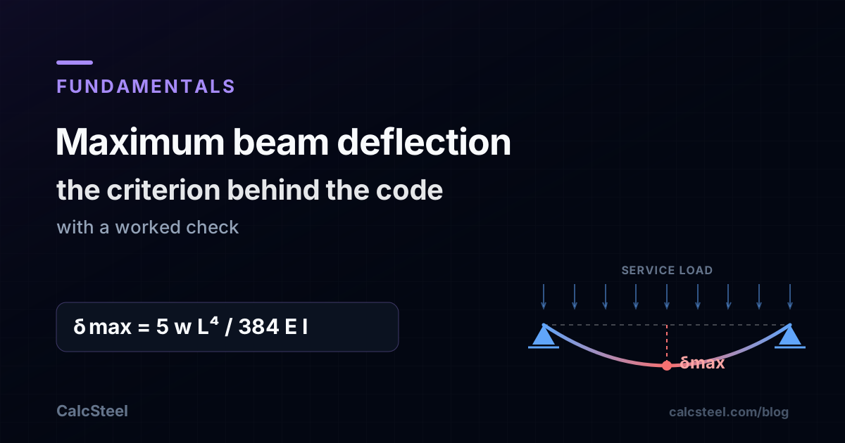
Maximum beam deflection is the single number serviceability turns on: not the average sag, but the largest vertical movement anywhere along the member under service load. A beam can pass every strength check and still fail this one, because the code does not cap the force in the beam, it caps how far the beam moves. This article gives the four closed forms that produce that peak, shows where along the span it actually lands, follows a real beam through the calculation on the shipping CalcSteel engine, and turns the answer into the span over deflection ratio a code compares against.
Key takeaways
- Maximum beam deflection is the peak of the elastic curve under service load, and it is what serviceability limits govern, not strength.
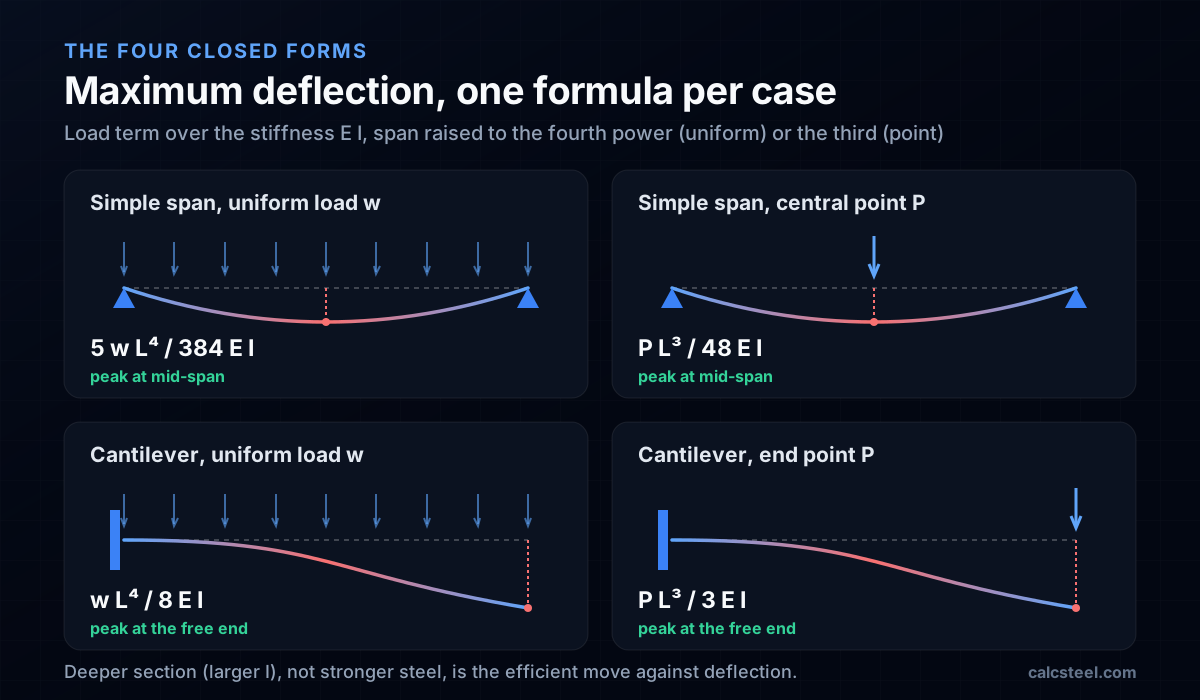
- Four closed forms cover most of practice: 5 w L^4 / 384 E I and P L^3 / 48 E I for a simple span, w L^4 / 8 E I and P L^3 / 3 E I for a cantilever.
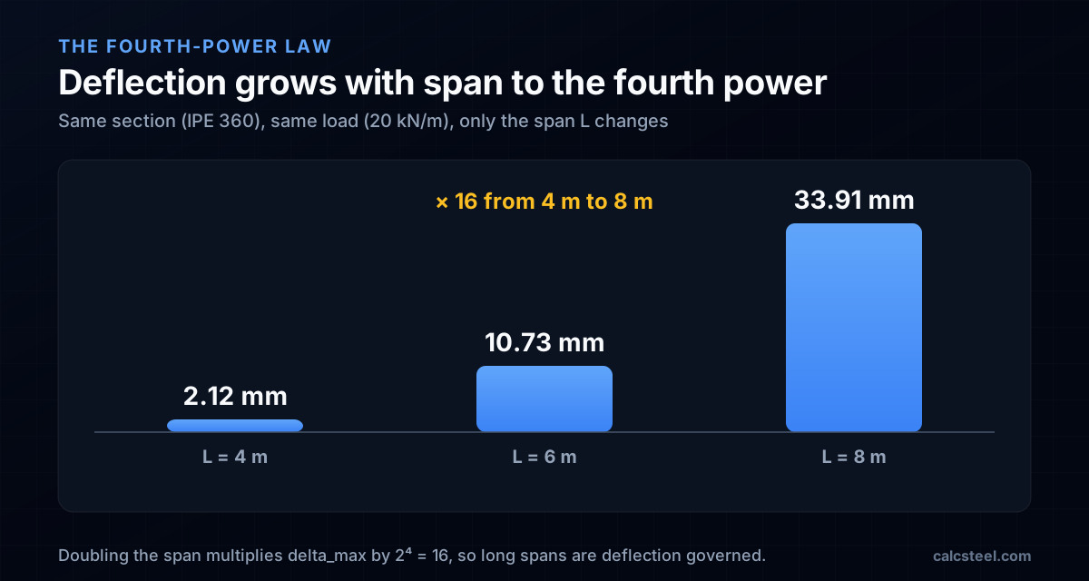
- Deflection scales with the fourth power of span: doubling L multiplies the sag by 16, which is why long spans are almost always deflection governed.
- The engine reproduces every one of the four formulas to four significant figures (ratio 1.000), so the closed form is exactly what the FEM solves.
- The code compares delta_max as a ratio L / delta against a limit such as L/360 or L/250, checked under the right service load, live alone for one limit and total for the other.
The one number serviceability turns on
Ask a strength check whether a beam is fine and it answers about stress: does the moment stay under the section's capacity. Ask an occupant and the answer is about movement: does the floor bounce, does the plaster crack, does the door still close. Those two questions are decided by different numbers, and the second one is maximum beam deflection, delta_max, the largest vertical movement anywhere along the member under service load.
It is a serviceability quantity, so it is computed under unfactored service loads, not the factored loads of a strength combination. And it is a maximum, a single worst point on the deflected shape, which is why the whole calculation reduces to one closed form per case and one comparison. This article builds delta_max from its formula, finds where along the span it lands, runs a real beam through the shipping CalcSteel FEM engine, and converts the result into the span over deflection ratio the code actually reads. For the limits themselves, the companion pillar on deflection limits in steel design codes traces where L/360 came from and what each code requires; this one is about producing the number you compare against it.
What maximum beam deflection actually means
Under load a beam bends into a smooth curve, the elastic curve, described by the differential equation E I d2y/dx2 = M(x). Integrate the bending moment twice, apply the support conditions, and you have y(x), the vertical movement at every point. Maximum beam deflection is simply the largest magnitude of that curve:
delta_max = max over x of |y(x)|
Two properties of that definition matter in practice. First, delta_max is a displacement, measured in millimetres, and it is governed by stiffness E I, not by strength. A beam that is strong but flexible sags a lot; a beam that is stiff but lightly built barely moves. Second, the maximum lives where the slope of the curve is zero, dy/dx = 0, which is the point of zero rotation. That is not always mid-span, and it is not the same point as the maximum moment, a distinction the section on location returns to. Everything else, the four formulas below, the code ratio, the worked check, is bookkeeping on top of these two facts.
The four closed forms that cover most of practice
Integrating E I d2y/dx2 = M(x) for the standard load and support cases gives the deflection formulas that sit in every handbook. Four of them cover the large majority of everyday members: a simple span under a uniform load or a central point load, and a cantilever under a uniform load or an end point load. In each, delta_max is the peak of the curve and it is set by the load, the span to a power, and the stiffness E I.
| Case | Maximum deflection | Where it occurs |
|---|---|---|
| Simple span, uniform load w | 5 w L^4 / (384 E I) | mid-span |
| Simple span, central point load P | P L^3 / (48 E I) | mid-span |
| Cantilever, uniform load w | w L^4 / (8 E I) | free end |
| Cantilever, end point load P | P L^3 / (3 E I) | free end |
Read the powers of L, because they carry the intuition. A uniform load raises span to the fourth power; a point load to the third. That single exponent, four for distributed and three for concentrated, is why span dominates deflection more than any other variable, and it is the subject of its own section below. The coefficients, 5/384, 1/48, 1/8, 1/3, are pure geometry of the load and support arrangement; they never change for these cases. For anything outside the four, a partially loaded span, an overhang, a fixed-end beam, a two-span continuous member, the same integration gives a different coefficient, and a virtual work or slope-deflection hand calculation, or the FEM engine, produces the number directly.
Where the maximum lands, and why it is not the max moment
The peak of the deflected shape is where the slope is zero. For a symmetric case, a simple span under a symmetric load or a cantilever, symmetry puts that point at the obvious place: mid-span for the simple beam, the free end for the cantilever. The trap is asymmetry. Move the point load off centre, add an overhang, or make the two spans of a continuous beam unequal, and the zero-slope point drifts away from mid-span, so reading the deflection at the middle underestimates the true maximum.
It is also a different point from the maximum bending moment. Maximum moment sits where shear crosses zero, dM/dx = V = 0. Maximum deflection sits where slope crosses zero, dy/dx = 0. On a simple span under a uniform load both happen to fall at mid-span, which quietly trains the habit that they coincide, but they are answers to two different integrals and in general they separate. The safe rule is to take delta_max from the whole curve, not from a nominated section: report the largest |y| the analysis finds, wherever it is. The shear and bending moment diagrams locate the moment peak; the deflected shape locates the deflection peak, and they are read separately.
What drives the number: E I and the fourth-power law
Every formula in the table is a load term over E I. The stiffness E I is the whole story of how much a beam moves, and it splits cleanly. E, the modulus of elasticity, is a material constant, about 200 GPa (20000 kN/cm2) for all structural steel, mild or high strength alike, which is why a higher grade does nothing for deflection: same E, same sag. I, the second moment of area, is geometry, and it is where the designer has leverage, because I grows with the cube of depth. Making a section deeper is the efficient move against deflection; making it stronger is not.
Against E I sits the span, and the span wins. Hold the load and the section fixed on a simple span under a uniform load, IPE 360 carrying 20 kN/m, and let only the length change:
| Span L | delta_max = 5 w L^4 / 384 E I |
|---|---|
| 4 m | 2.12 mm |
| 6 m | 10.73 mm |
| 8 m | 33.91 mm |
From 4 m to 8 m the span doubles and the deflection goes from 2.12 to 33.91 mm, a factor of 15.995, which is 2^4 to within rounding. That is the fourth-power law made concrete: deflection is far more sensitive to span than to anything else on the page. It is the reason long-span floors and roofs are almost always sized by deflection rather than by strength, and the reason the first honest question about any sagging beam is not how heavy the load is but how long the span is.
The criterion behind the code: a ratio, not a millimetre
No code caps deflection in millimetres, because 20 mm is generous on a 12 m span and alarming on a 3 m one. What matters to the plaster and the occupant is the sag relative to the span, so the criterion is a ratio: delta_max expressed as L / delta, checked against a limit such as L/360, L/300 or L/250. Divide the span by your computed deflection and compare the denominator: a beam at L/503 is well inside an L/360 limit; a beam at L/300 has just met an L/300 limit.
Two details decide whether the check is done correctly. The first is which service load. Codes attach different limits to different loads: a tighter one, often L/360, to the variable (live) load alone, because that is the movement an occupant sees day to day, and a looser one, often L/250, to the total load, dead plus live. You compute a deflection for each load and check it against its own limit; the governing case is whichever has the higher utilisation, not the larger deflection. The second is that deflection superposes: because the response is linear elastic, the deflection under dead plus live equals the deflection under dead plus the deflection under live, which is what lets you split the checks cleanly. The limit values themselves, and how EN 1993, AISC 360, NBR 8800 and IS 800 differ on them, are laid out in the deflection limits pillar; here we produce the ratio and apply it.
A worked check: an IPE 360 floor beam over 7 metres
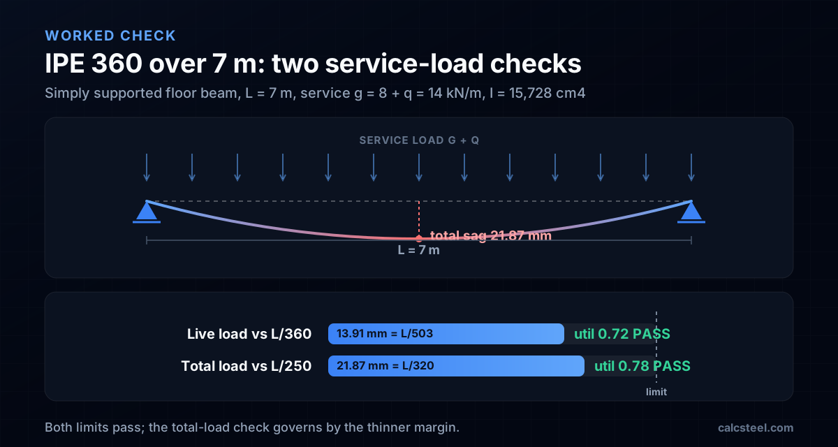
Take a real member. A simply supported floor beam, IPE 360, spanning L = 7.0 m, carrying service loads of g = 8 kN/m permanent and q = 14 kN/m variable. The analysis carries I = 15,728 cm4 for this section and E = 20000 kN/cm2. Both limits in play are the common floor pair: L/360 on the live load, L/250 on the total.
Compute the two deflections from 5 w L^4 / 384 E I, one per load, then read each as a ratio and check it:
| Load | delta_max | as L / delta | Limit | Allowed | Utilisation | Verdict |
|---|---|---|---|---|---|---|
| Live, q = 14 kN/m | 13.91 mm | L/503 | L/360 | 19.44 mm | 0.72 | PASS |
| Total, g + q = 22 kN/m | 21.87 mm | L/320 | L/250 | 28.00 mm | 0.78 | PASS |
The live-load deflection is 13.91 mm, which is the span divided by 503, comfortably inside the L/360 limit of 19.44 mm at a utilisation of 0.72. The total-load deflection is 21.87 mm, or L/320, inside L/250 at 0.78. The beam passes both, and the total-load case governs by the thinner margin. Note the superposition working underneath: the live part alone is 13.91 mm, the dead part alone is 7.96 mm, and their sum, 21.87 mm, is exactly the total-load deflection the engine returns, which is the linearity the split relies on. Every number here is the shipping FEM engine's output, hand-checked against the closed form, and the next section shows that agreement in full.
The engine reproduces the formula to four figures
A formula is only worth trusting if an independent solver lands on the same number. We ran each of the four canonical cases on the shipping CalcSteel FEM engine, the same solver the 3D editor uses, and compared its deflection to the closed form evaluated with the identical section stiffness. The agreement is exact to four significant figures, ratio 1.000 in every case:
| Case | Formula | Closed form | FEM engine | Ratio |
|---|---|---|---|---|
| Simple span, w = 20 kN/m, L = 6 m | 5 w L^4 / 384 E I | 10.729 mm | 10.729 mm | 1.000 |
| Simple span, P = 50 kN, L = 6 m | P L^3 / 48 E I | 7.153 mm | 7.153 mm | 1.000 |
| Cantilever, w = 20 kN/m, L = 3 m | w L^4 / 8 E I | 6.438 mm | 6.438 mm | 1.000 |
| Cantilever, P = 30 kN, L = 3 m | P L^3 / 3 E I | 8.583 mm | 8.583 mm | 1.000 |
All four sections are IPE 360, so the only thing changing across the rows is the load case and the span, and the closed form tracks the FEM step for step. That is the point of the exercise: the hand formula and the matrix solver are solving the same beam equation, so when a project needs a number outside the four cases, the engine can be trusted to extend the same physics the formulas encode.
Try it: compute your own maximum deflection
Enter a span, a section and a load below and the calculator returns the maximum deflection, its location, and the span over deflection ratio, alongside the moment and shear. It is the fastest way to see the fourth-power law move: change only the span and watch delta_max climb far faster than the length does. For a full member with real supports, load cases and a code deflection limit applied automatically, the same model opens in the CalcSteel 3D editor.
Max moment
45 kN·m
Max shear
30 kN
Max deflection
10.55 mm
= L/569
Bending stress σ
84.4 MPa
σ = M/Sx
Utilization
44.0%
NBR 8800 · δ ≤ L/250
Geometry & supports
Section
Ix 7999 cm⁴ · Sx 533 cm³ · 42.2 kg/m
Point loads (↓ positive)
None — add as many as you need.
Distributed loads (uniform or trapezoidal)
Model sketch
Diagrams — free PNG / SVG / CSV export, no watermark
Step-by-step — the calculation memory of YOUR beam
IPE 300 · L = 6 m · fy = 250 MPa
1. Reactions (equilibrium of the solved FEM model)
ΣFy = 0 · ΣM = 0
R_A = 30 kN · R_B = 30 kN
2. Peak shear (read from the SFD)
Vmax = |V(x)|max
Vmax = -30 kN @ x = 6 m
3. Peak moment (read from the BMD)
Mmax = |M(x)|max
Mmax = 45 kN·m @ x = 3 m
4. Peak deflection
EI = 15998 kN·m² (E = 200 GPa)
δmax = 10.55 mm @ x = 3 m = L/569
5. Elastic bending stress
σ = Mmax / Sx = 45.00 × 10³ / 533.3
σ = 84.4 MPa
6. Bending check — both codes, side by side
NBR 8800: σ ≤ fy/1.10 = 227.3 MPa · AISC 360: σ ≤ 0.90·fy = 225 MPa
NBR 37.1% PASS · AISC 37.5% PASS
7. Deflection check (serviceability — code-independent)
δ ≤ L/250 = 24 mm
10.55 mm / 24 mm = 44.0% PASS
Recomputed live from the current inputs by the direct-stiffness FEM engine — change any load and every step updates. Reproduce it by hand with the formulas in the sections below.
Lightest catalog profiles that pass (974 flexural candidates · NBR 8800)
| Profile | Std | Weight | Total steel | σ util | δ util | |
|---|---|---|---|---|---|---|
| W310x21 | AISC | 21 kg/m | 126 kg | 83% | 98% | |
| VS 300x23 | BR | 22.6 kg/m | 136 kg | 71% | 84% | |
| U 300x90x6.3 | BR | 23.1 kg/m | 139 kg | 82% | 98% | |
| U 300x100x6.3 | BR | 24.1 kg/m | 145 kg | 77% | 91% | |
| VS 250x25 | BR | 24.6 kg/m | 148 kg | 70% | 100% |
Elastic bending (σ = M/Sx vs fy/γa1, γa1 = 1.10 — NBR 8800) + deflection screening of the full flexural catalog. Lateral-torsional buckling, shear and local buckling are NOT checked here — run the full NBR 8800 / AISC 360 verification in the 3D editor.
Superposition, camber and the long game
Two moves extend the basic calculation. The first is superposition, already used in the worked check: because a steel beam under service load is linear elastic, deflections from separate load cases add, so a combined pattern can be built from the simple cases in the table rather than integrated from scratch. A beam under a uniform load plus a central point load deflects by the sum of 5 w L^4 / 384 E I and P L^3 / 48 E I, no new integration needed.
The second is camber, fabricating the beam with a built-in upward curve so that the permanent, dead-load part of the deflection is cancelled and the beam sits flat once the structure is up. Camber offsets the dead-load sag; it does nothing for the live-load deflection, which still has to pass its own limit, and it is usually specified only above a threshold span. Beyond the elastic picture, two long-term effects push the real deflection higher than the formula: the slab a composite beam carries creeps, and any sustained load on a member with a concrete component grows over years. Those belong to a serviceability assessment of the finished floor, covered in the serviceability, deflection and vibration pillar; the elastic delta_max here is the starting point they build on.
Five ways a deflection number goes wrong
The formula is simple, which is exactly why the errors are quiet ones.
- Checking delta instead of delta over L. A raw millimetre figure means nothing without its span. Always reduce to L / delta before comparing to a limit.
- The wrong second moment of area. Deflection uses the axis the beam bends about, the strong axis I for an ordinary floor beam. Slip in the weak-axis value and the deflection is off by an order of magnitude. And beware the source of I itself: a handbook may list about 16,300 cm4 for an IPE 360 while a software model carries 15,700, a few-percent spread that comes from how the root fillets are modelled. Keep one consistent source for a given check.
- Factored loads on a serviceability check. delta_max is a service-load quantity. Feeding it the 1.35 or 1.6 factored loads of a strength combination inflates the deflection by that factor and fails beams that are fine.
- Reading deflection at mid-span by habit. For an asymmetric load or an overhang the peak is not at the middle. Take the maximum of the whole curve, not the value at a nominated point.
- Forgetting the load split. The live-load limit and the total-load limit are separate checks against separate loads. Running only the total misses the case the tighter live-load limit is there to catch.
Maximum beam deflection: quick answers
What is the formula for maximum deflection of a simply supported beam? Under a uniform load it is 5 w L^4 / 384 E I at mid-span; under a central point load it is P L^3 / 48 E I, also at mid-span.
What is the maximum allowable deflection of a steel beam? It is a ratio of the span, not a fixed millimetre value: common limits are L/360 for live load and L/250 for total load, with the exact values set by the code and the element. See the deflection limits pillar.
Where does the maximum deflection occur? Where the slope of the deflected shape is zero. For symmetric cases that is mid-span or the free end of a cantilever; for asymmetric loading it shifts, and it is not generally the point of maximum moment.
Does a higher steel grade reduce deflection? No. Deflection depends on E, which is about 200 GPa for every structural steel. A stronger grade changes capacity, not stiffness. To cut deflection, add depth, which raises I.
Why is span so important? Maximum deflection scales with L^4 for a distributed load. Doubling the span multiplies the sag by 16, so span is the dominant variable and long members are usually deflection governed.
Key takeaways
Maximum beam deflection is the peak of the elastic curve under service load, governed by stiffness E I and checked as a ratio L / delta against a code limit. The four closed forms, 5 w L^4 / 384 E I and P L^3 / 48 E I for a simple span, w L^4 / 8 E I and P L^3 / 3 E I for a cantilever, cover most members, and the FEM engine reproduces them to four significant figures. Deflection scales with span to the fourth power, so long spans are deflection governed; a higher steel grade does nothing, because E is the same for every grade; and the check is only right when it is done against the correct service load, live for one limit and total for the other.
Sources
- 1.EN 1993-1-1:2005 Eurocode 3, Design of steel structures, Part 1-1, clause 7.2 (serviceability limit states, deflections) and clause 3.2.6 (material properties of steel)
- 2.EN 1990:2002 Eurocode, Basis of structural design, Annex A1.4 (serviceability limit states, vertical deflection limits)
- 3.ANSI/AISC 360-22, Specification for Structural Steel Buildings, Chapter L (design for serviceability) and Commentary
- 4.AISC Design Guide 3, Serviceability Design Considerations for Steel Buildings, 2nd ed., West and Fisher
- 5.Warren C. Young and Richard G. Budynas, Roark's Formulas for Stress and Strain, 8th ed., Table 8.1 (beam deflection formulas)
- 6.ABNT NBR 8800:2008, Projeto de estruturas de aco e de estruturas mistas de aco e concreto de edificios, Anexo C (deslocamentos maximos)
Try CalcSteel for free
Model, analyze and design steel structures in your browser. No install, no signup.
Open the 3D editor