Material Yield Criteria: von Mises and Tresca on One Structural Detail, and the 15.470 % Between Them
A yield criterion is the bridge between the six numbers of a stress state and the one number a code compares against fy. Two have survived a century of testing: von Mises, an ellipse, and Tresca, the hexagon inscribed in it. They agree exactly at six points, they never disagree by more than 2/√3 = 15.470 %, and the whole of that gap sits at a single stress state. This article puts both criteria on the same real connection, depth by depth, using the internal forces the CalcSteel engine returned, and finds the one plate where the choice flips the verdict and the eight member ends where it changes nothing at all.
Key takeaways
- A yield criterion answers one question: this point has σ and τ acting together, so how close is it to the uniaxial test that produced fy? von Mises answers √(σ² + 3τ²) and Tresca answers √(σ² + 4τ²).
- The two never differ by more than 2/√3 = 1.154701, which is 15.470 %, and Tresca is always the conservative one. The hexagon is inscribed in the ellipse and touches it at six points, so the disagreement is bounded by geometry, not by judgement.
- The entire 15.470 % lives at one stress state: pure shear. At σ = 0 the gap is exactly 2/√3, and it falls away fast. At τ/σ = 0.1463 the gap is already down to 1 %, and at τ/σ = 0.3847 it is 5 %.
- On one section of one beam the gap runs the full range. At the connection of an IPE 450 the engine returned V = 203.58 kN and M = 20.62 kN·m, and across that section the gap is 15.470 % on the neutral axis, 14.958 % at the web to flange junction and 0.000 % at the extreme fibre.
- Where the member is bending-governed the criterion is irrelevant. At the quarter point the governing stress is 223.34 MPa under both criteria, identical to five figures, because the governing point is the flange tip and the flange tip is in pure tension.
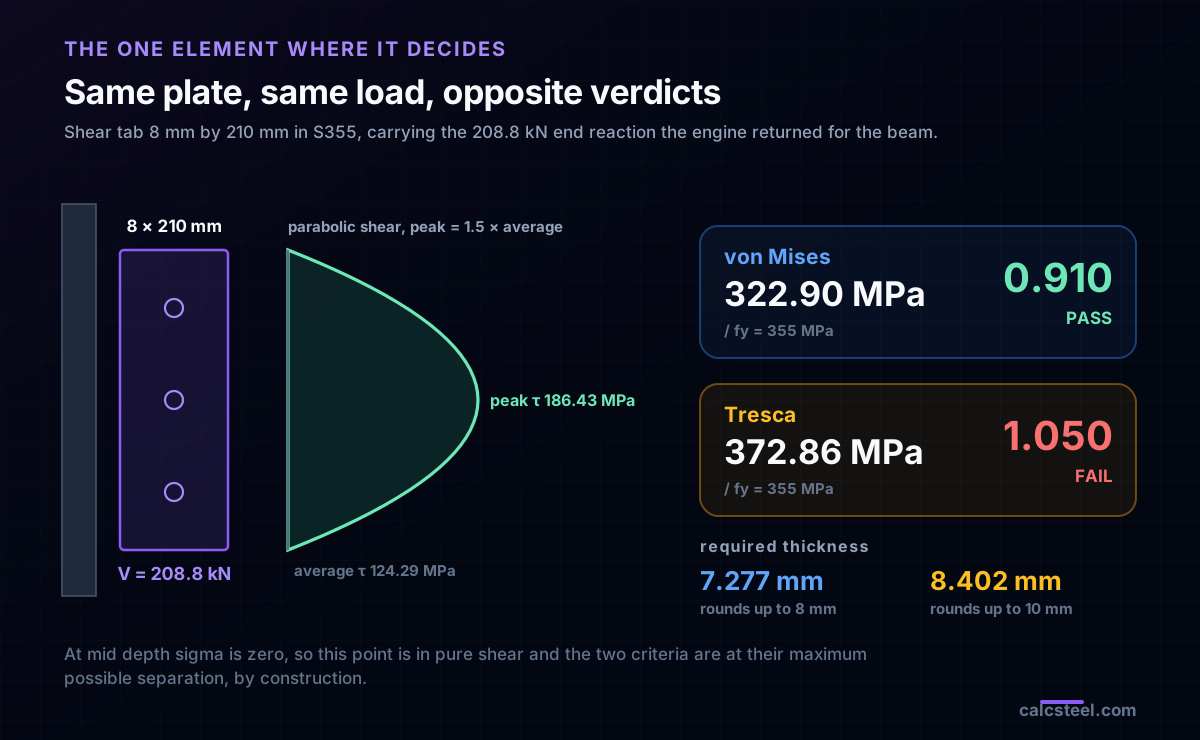
- It decides on the thin plate. The 8 mm by 210 mm shear tab carrying the engine's 208.8 kN reaction reaches 322.90 MPa by von Mises and 372.86 MPa by Tresca. Against S355 that is 0.910, a pass, against 1.050, a fail, on the same plate on the same day.
- Written as thickness, the same disagreement is 7.277 mm against 8.402 mm of required tab. One rounds up to 8, the other rounds up to 10.
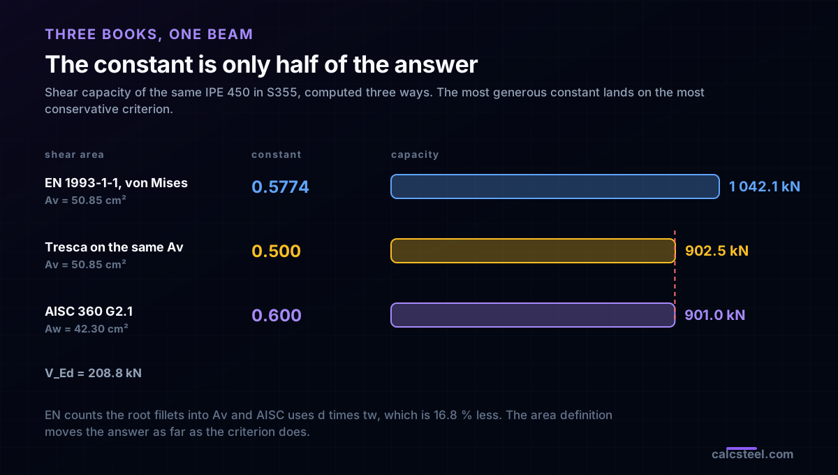
- The codes have already made the choice for you and hidden it in a constant. Tresca yields in shear at 0.500 fy, von Mises at 0.5774 fy, and AISC 360 writes 0.600 fy.
- The constant matters less than the area it multiplies. On this IPE 450, EN 1993-1-1 gives Vpl,Rd = 1042.1 kN with Av = 50.85 cm² and AISC 360 gives Vn = 901.0 kN with Aw = 42.30 cm². The two land 15.7 % apart, almost exactly the criterion gap, for a reason that has nothing to do with criteria.
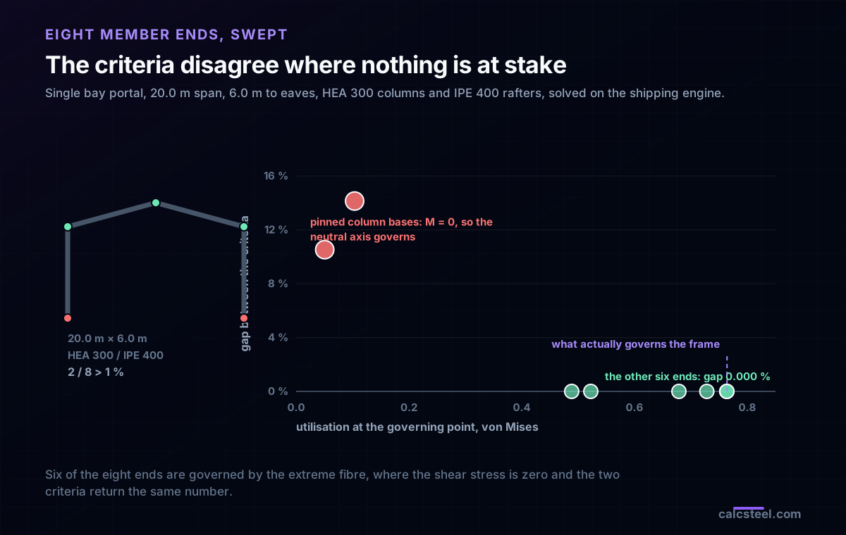
- Across the eight member ends of a portal frame, six showed a gap of 0.000 % and the two that exceeded 1 % were the pinned column bases, at utilisations of 0.051 and 0.104. The criteria disagree loudest exactly where nothing is at stake.
- Steel codes chose von Mises because the metal did. Taylor and Quinney's thin-walled tube tests in 1931 landed between the two surfaces and much closer to the ellipse, and ASME moved Division 2 from Tresca to von Mises in its 2007 rewrite for the same reason.
One plate, one load, two verdicts
An 8 mm plate, 210 mm deep, S355, welded to a column flange and bolted to a beam web. It carries 208.8 kN, which is what the CalcSteel engine returned as the end reaction of the beam sitting on it. Nothing unusual anywhere.
Check it against yield and you get two answers.
- By von Mises, the peak equivalent stress is 322.90 MPa. Against fy = 355 MPa that is a utilisation of 0.910. The plate passes.
- By Tresca, the same point is at 372.86 MPa. Utilisation 1.050. The plate fails.
Same plate, same load, same steel, same day. The two numbers are 15.470 % apart, and that is not a coincidence or a rounding difference. It is exactly 2/√3, the largest gap the two criteria are capable of, and this plate hits it on the nose because it is in pure shear.
Written as thickness rather than as a ratio, the disagreement is 7.277 mm against 8.402 mm of plate. One rounds up to an 8 mm plate, the other rounds up to a 10 mm plate. That is the whole subject in one detail.
What follows is the same question asked everywhere else on the same structure: through the full depth of the beam section, at three stations along the span, and at all eight member ends of a portal frame. The answer turns out to be sharply uneven. The 15.470 % is real, it is bounded, and almost everywhere it is in the wrong place to matter.
What a yield criterion is actually for
Every allowable you have ever used traces back to one experiment: a round bar pulled in one direction until it yields. That test produces one number, fy, and it describes one stress state, pure uniaxial tension.
Real points in real structures are almost never in that state. A point in a beam web has a normal stress σ from bending and a shear stress τ from the shear force at the same instant. A point in a shear tab has τ and nothing else. A point at a weld root has all of it. You cannot compare a state to a number until you have converted the state into a number, and the rule that does the converting is the yield criterion.
So the question a criterion answers is narrow and precise:
This point has σ and τ acting together. What single uniaxial stress would be equally dangerous?
Call the answer the equivalent stress. Once you have it, the check is the schoolbook one again: equivalent stress against fy, divided by whatever partial factor the code attaches.
For the plane state that dominates structural steelwork, one normal stress and one shear stress, the two surviving criteria give:
- von Mises: σeq = √(σ² + 3τ²)
- Tresca: σeq = √(σ² + 4τ²)
The 3 and the 4 are the entire argument. Everything else in this article is a consequence of those two coefficients.
If you want to see where the σ and τ at a point come from in the first place, the companion article on the stress tensor builds the full Cauchy tensor on a real bracket. This one takes the state as given and argues about what to do with it.
An ellipse and the hexagon inside it
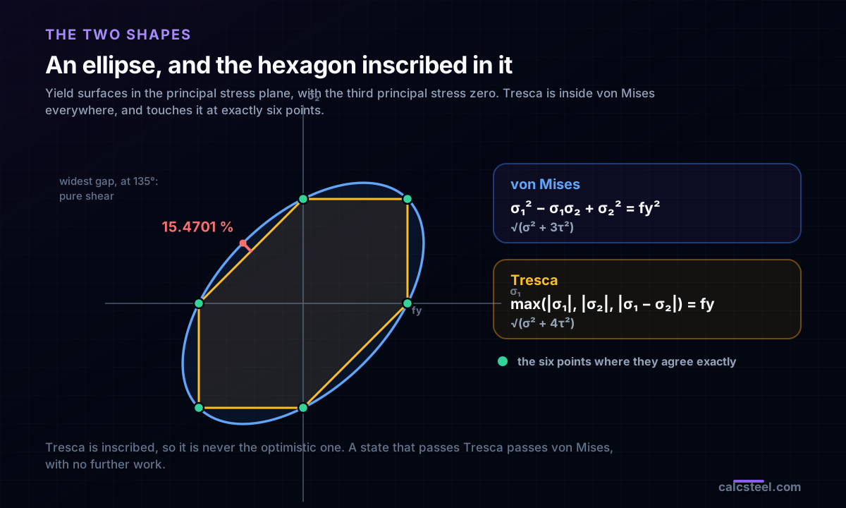
Plot every stress state that is exactly at yield and you get a surface. In the plane of the two principal stresses σ₁ and σ₂, with the third one zero, the two criteria draw two shapes.
von Mises draws an ellipse: σ₁² − σ₁σ₂ + σ₂² = fy². Its long axis runs along the line σ₁ = σ₂, the pressure direction, which is the criterion saying that squeezing a point equally from all sides does not yield it. Only distortion does.
Tresca draws a hexagon: the largest of |σ₁|, |σ₂| and |σ₁ − σ₂| equals fy. It is the criterion saying that yielding starts when the maximum shear stress in the point reaches half of fy, which is what the uniaxial test shows at the moment it yields.
The relationship between them is fixed and it is worth stating carefully, because it is what bounds the whole disagreement:
- The hexagon is inscribed in the ellipse. Tresca is therefore always the conservative one, everywhere, without exception.
- They touch at six points, the hexagon's vertices: the uniaxial states (fy, 0), (0, fy), (−fy, 0), (0, −fy) and the equal-biaxial states (fy, fy) and (−fy, −fy). Substituting each of the six into the ellipse equation returns exactly 1.000000, which is the check the simulation runs before drawing anything.
- The largest gap sits at the hexagon's edge midpoints, and the sweep confirms it: scanning all 360 radial directions, the worst is at 135°, the pure shear direction σ₁ = −σ₂, where the ellipse is 15.4701 % further out than the hexagon.
That is the ceiling on the entire argument. Whatever the stress state, the two criteria cannot be more than 15.470 % apart, and Tresca is never the optimistic one. As disagreements in engineering go, this is an unusually well-behaved one.
The whole disagreement lives at one stress state
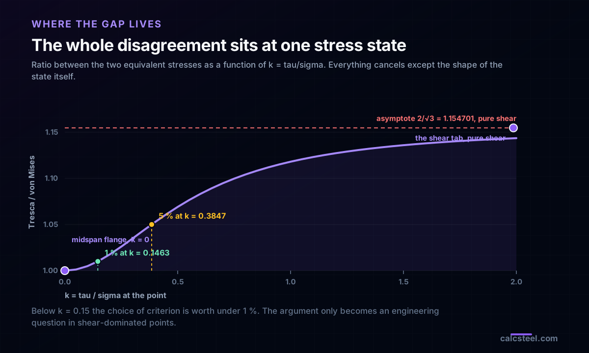
Take the ratio of the two equivalent stresses and everything cancels except the shape of the state itself. Writing k = τ/σ:
Tresca / von Mises = √(1 + 4k²) / √(1 + 3k²)
Sweeping k from 0 to 2 and asserting that expression against the criteria evaluated directly gives agreement to 1e-12, which is the algebra check. The shape of the curve is the point:
- k = 0, pure normal stress. The ratio is exactly 1.000000. The criteria are the same criterion.
- k = 0.1463. The gap reaches 1 %.
- k = 0.3847. The gap reaches 5 %.
- k → ∞, pure shear. The ratio goes to 2/√3 = 1.154701, and it is asymptotic, so 15.470 % is approached and never passed.
Read that as a practical statement and it says something blunt. A point needs to be seriously shear-dominated before the choice of criterion moves the number by even 5 %. Below τ = 0.38σ the two criteria are, for design purposes, the same tool.
This is also why the argument is so often theoretical. In a structure designed by members rather than by finite elements, the points that decide the design are usually the ones where k is small. The points where k is large are usually nowhere near their limit. The next three sections are that claim, tested.
The detail, and where its numbers come from
The structure is deliberately ordinary. An IPE 450 in S355, simply supported over 8.0 m, carrying g = 22.0 kN/m of permanent load and q = 15.0 kN/m of variable load. The EN 1990 persistent design combination gives 1.35 × 22.0 + 1.5 × 15.0 = 52.2 kN/m.
The engine was calibrated before it was trusted. Solved with a plain UDL, it returns wL²/8 and wL/2 with an error of 0.000000 %, and the midspan deflection against 5wL⁴/384EI with an error of 0.000010 %. Only then were the design numbers taken:
- Peak bending moment 417.6 kN·m, and against the section's elastic modulus Wel = 1447.92 cm³ that is a bending stress of 288.41 MPa, a utilisation of 0.812 against S355.
- End reaction 208.8 kN. This is the number the connection carries.
The connection is a single-plate shear tab, 8 mm thick and 210 mm deep, welded to the supporting column and bolted to the beam web. This detail was chosen for a reason that will become obvious: a shear tab is the one element in an ordinary steel frame whose governing point sits at k → ∞.
Every stress below is built from the engine's own M and V and the profile registry's own geometry: Ix = 32578.28 cm⁴, tw = 9.4 mm, tf = 14.6 mm, b = 190 mm, h = 450 mm. The first moment of area Q(y) is computed from that geometry rather than read from a table, because the registry's stored plastic modulus is known to be half its correct value and is not used anywhere in this article. Section properties ignore the root fillets, so Ix sits a few per cent below the published catalogue value, and demand and capacity are both on that basis.
One section, and the gap runs the full range
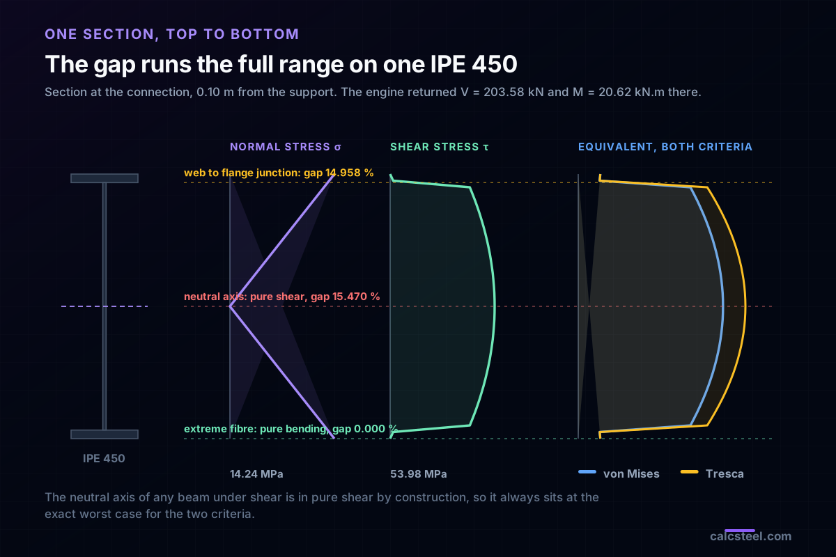
Take the beam section right at the connection, 0.10 m from the support. The engine gives V = 203.58 kN and M = 20.62 kN·m there: nearly all shear, almost no bending. Now walk down the depth of that one section, evaluating σ = M·y/Ix and τ = V·Q(y)/(Ix·t) at 41 depths, and apply both criteria at every one.
The gap between them is not a property of the section. It is a property of each point, and on this single section it sweeps the entire possible range:
- Extreme fibre, y = ±225 mm. Q = 0, so τ = 0 and the state is pure bending. The gap is exactly 0.000 %, asserted to 1e-6. The criteria are identical here, and they always are at the outer fibre of any beam.
- Web to flange junction, y = 210.4 mm, taken on the web side where the thickness is tw. σ = 13.32 MPa, τ = 40.15 MPa. von Mises 70.80 MPa, Tresca 81.39 MPa. Gap 14.958 %. This is the point EN 1993-1-5 §7.1 sends you to, and the shear stress here drops by a factor of b/tw = 20.2 the moment you step across into the flange, where the same Q is divided by 190 mm instead of 9.4 mm.
- Neutral axis, y = 0. σ = 0 by definition and τ peaks at 53.98 MPa, using Q = 811.96 cm³ over tw = 9.4 mm. von Mises 93.49 MPa, Tresca 107.96 MPa. Gap exactly 15.470 %.
That last line is worth pausing on. The neutral axis of any beam under shear is in pure shear by construction, so it always sits at the exact worst case for the two criteria. If you go looking for the maximum disagreement between von Mises and Tresca in a steel structure, you will find it on the neutral axis of every single bending member, guaranteed, in full.
And it will almost never matter, for the reason the next section makes precise.
Why the gap is always in the wrong place
A cross-section check does not care about the average point. It cares about the governing one, the point with the highest equivalent stress. So the honest question is not how big is the gap, it is how big is the gap where the section is actually governed.
Three stations along the same 8.0 m beam answer it:
| Station | M (kN·m) | V (kN) | Governing von Mises | Governing Tresca | Gap | Utilisation |
|---|---|---|---|---|---|---|
| At the tab, x = 0.10 m | 20.62 | 203.58 | 93.49 MPa | 107.96 MPa | 15.470 % | 0.263 / 0.304 |
| Quarter point, x = 2.10 m | 323.38 | 99.18 | 223.34 MPa | 223.34 MPa | 0.000 % | 0.629 / 0.629 |
| Midspan, x = 4.10 m | 417.34 | 5.22 | 288.23 MPa | 288.23 MPa | 0.000 % | 0.812 / 0.812 |
The pattern is exact and it is not an accident. At the quarter point and at midspan the governing point is the extreme fibre, where τ = 0, so the criteria return the same number to five significant figures. At the tab station the governing point is the neutral axis, because there is barely any bending, so the gap is the full 15.470 %.
But look at the last column. The station where the criteria disagree by 15.470 % is running at a utilisation of 0.263. The station that governs the beam is at 0.812 and the criteria agree there exactly. The disagreement is real and it is confined to the part of the structure that has capacity to spare.
This is the structural version of a very general fact: bending wins the argument about where the peak stress is, and bending is the state where the two criteria are the same criterion.
The one element where it decides
Now the plate from the first section, in full.
The tab is 8 mm by 210 mm, gross area 16.8 cm², carrying the engine's 208.8 kN reaction. A rectangle in shear has a parabolic shear distribution, so the peak is 1.5 times the average:
- Average shear stress, V/A = 208.8/16.8 = 124.29 MPa.
- Peak shear stress at mid depth, 1.5 × 124.29 = 186.43 MPa.
- At that point σ = 0. This is pure shear, so the criteria are at their maximum separation, by construction.
- von Mises: √3 × 186.43 = 322.90 MPa. Utilisation against S355 with γM0 = 1.0: 0.910.
- Tresca: 2 × 186.43 = 372.86 MPa. Utilisation: 1.050.
The verdicts are opposite, and unlike the beam stations there is no high-utilisation bending point elsewhere in the plate to overrule them. The shear tab has no other check to hide behind: it is the shear-critical element.
Turn the same disagreement into the thing that gets ordered from the mill and it becomes concrete. The thickness required to bring the utilisation to exactly 1.0 is 7.277 mm by von Mises and 8.402 mm by Tresca. Rounded to stock, that is an 8 mm plate against a 10 mm plate, a 25 % increase in the plate weight of every shear tab in the job, decided entirely by which of two equations from the 1860s and the 1910s you opened.
One caveat, and it is a large one, treated properly two sections down: the numbers above are the peak point stresses, which is what a finite element plate model reports. Every steel code checks the tab on the average shear instead, and that modelling choice is worth 50 %, more than three times the criterion gap.
Try it: put a state in and watch both criteria move
The fastest way to build intuition for the ratio curve is to move a stress state around and watch the principal stresses respond. Enter the neutral axis state of the beam at the tab, σ = 0 and τ = 53.98 MPa, and read the principal stresses: they come back as +53.98 and −53.98 MPa, equal and opposite, which is the signature of pure shear and the exact state where the criteria are 15.470 % apart.
Then add bending. Enter the web to flange junction at the quarter point, σ = 208.85 MPa with τ = 19.56 MPa, and the circle slides away from the origin until it nearly touches it. That is k = 0.094, and the gap has already fallen to 0.426 %.
σ₁ (major)
92.4MPa
σ₂ (minor)
7.6MPa
τmax in-plane
42.4MPa
θp (to σ₁)
22.5°
τabs (3-D)
46.2MPa
von Mises
88.9MPa
η · NBR
0.28 ✓
Plane-stress state (MPa)
Tension positive. τxy positive = shear that tends to rotate the element counter-clockwise on the +x face.
Plane stress (σz = 0). Enable to inspect a genuine triaxial state — three circles, not two.
Code check — steel grade
σvM = 88.9 MPa ≤ 313.6 MPa = fy / γa1 (γa1 = 1.10)
NBR 8800:2008 §5.4.2.2 (γa1 = 1,10)
From your solved model
Solve a model in the CalcSteel 3D editor, then return here to load the real σx/σy/τxy at any member section — Mohr's circle becomes the solver's inspection lens.
Presets
Element rotation θ
0°Export (free · no watermark)
0.500, 0.5774, 0.600: the choice is already in the constant
You have probably never typed a yield criterion into a design check, because the codes made the choice for you and buried it in a coefficient. Set σ = 0 in each criterion and solve for the shear stress at yield:
- Tresca: τy = fy/2 = 0.500 fy. For S355, 177.50 MPa.
- von Mises: τy = fy/√3 = 0.5774 fy. For S355, 204.96 MPa.
- AISC 360: the specification writes 0.600 fy, in G2.1 for web shear and in J4.2 for shear yielding on the gross section. For S355, 213.00 MPa.
So AISC is not on either surface. It is 3.923 % above von Mises, which is a deliberate, documented rounding of 1/√3 upward, and 20.0 % above Tresca. Eurocode is explicit rather than rounded: EN 1993-1-1 §6.2.6 writes Vpl,Rd = Av·(fy/√3)/γM0, and the √3 in that formula is von Mises, spelled out. NBR 8800 follows the 0.60 convention. EN 1993-1-1 §6.2.1(5) goes further and gives you the criterion in the open, as the σ² + 3τ² ≤ fy² check.
Now the part that is worth more than the whole criterion argument. Apply all three constants to the shear capacity of the same IPE 450 and the answers do not line up the way the constants suggest:
| Basis | Area | Constant | Capacity |
|---|---|---|---|
| EN 1993-1-1, von Mises | Av = 50.85 cm² | 0.5774 | 1042.1 kN |
| Tresca on the same Av | Av = 50.85 cm² | 0.500 | 902.5 kN |
| AISC 360 G2.1 | Aw = d·tw = 42.30 cm² | 0.600 | 901.0 kN |
AISC, with the most generous constant of the three, lands at 901.0 kN, which is within 0.2 % of the answer you get from the most conservative criterion on the European area. The reason is that the two codes do not agree on what the shear area is. EN 1993-1-1 §6.2.6(3) includes the flange-to-web fillets and gives Av = A − 2b·tf + (tw + 2r)·tf = 50.85 cm². AISC uses the full depth times the web thickness, 45.0 × 0.94 = 42.30 cm², which is 16.8 % less.
The lesson is not that one code is right. It is that the criterion is one term in a product, and the other terms are just as capable of moving the answer by 15 %. Arguing about von Mises and Tresca while ignoring the area definition is arguing about the smaller half.
Eight member ends of a portal frame, swept
One beam is an anecdote. To see whether the criterion choice matters at the scale of a real frame, a single-bay portal was solved on the same engine: 20.0 m span, 6.0 m to eaves, HEA 300 columns, IPE 400 rafters, 12.0 kN/m on the roof and 4.5 kN/m of lateral load on the windward column, pinned bases. Then both criteria were applied at 41 depths of all eight member ends, with the axial stress N/A riding on every fibre.
The result is lopsided:
- Six of the eight ends showed a gap of 0.000 %. At every one of them the governing point is the extreme fibre, where the axial and bending stresses add and the shear stress is zero.
- Two ends exceeded 1 %, at 10.53 % and 14.14 %. Both are the pinned column bases, where M = 0 by definition and the section carries only N and V, so the governing point drops to the neutral axis.
- Those two ends are running at utilisations of 0.051 and 0.104. The frame is governed by the ridge and eaves moments, at 0.764 and 0.679, where the criteria agree exactly.
- The mean gap over all eight ends is 3.08 %, which is a statistic that describes nothing: it is the average of six zeros and two numbers from the least-loaded sections in the frame.
Meanwhile the neutral axis of every one of those eight sections has the full 15.470 % gap sitting on it, permanently. It just never carries more than 33.1 % of the section's governing stress, and at the ridge it carries 3.1 %.
That is the general shape of the answer. In frames designed member by member, the criterion choice is close to free. It stops being free the moment the load path passes through something thin and short: a shear tab, a coped beam web, a gusset, a link, a web panel in a moment connection, a stiffened opening. Those are the details where you should know which criterion your software is using, and they are exactly the details where a plate finite element model gets pointed at the structure.
Which one is right, and why steel chose the ellipse
The two criteria are not two opinions. They are two hypotheses about what physically triggers yielding in a ductile metal, and the experiments have been in for a long time.
Tresca (1864) proposed that yielding starts when the maximum shear stress reaches a critical value. It is simple, it is safe, and it has a clean physical picture: metals yield by slip on planes, and slip is driven by shear.
von Mises (1913), with Huber ahead of him in 1904 and Hencky giving it its physical reading in 1924, proposed that the trigger is the distortion energy stored in the point, which is the same as saying the second invariant of the deviatoric stress. That is why hydrostatic pressure does not appear in it: pressure changes volume, not shape.
Taylor and Quinney (1931) settled it experimentally. They loaded thin-walled copper, aluminium and mild steel tubes in combined tension and torsion, which is exactly the combined σ and τ state of a beam web, and measured where yield actually started. The points landed between the two surfaces and consistently much closer to the ellipse. For the ductile metals we build with, von Mises is simply the better fit.
Two practical consequences follow, and they point in opposite directions:
- Structural steel codes use von Mises, because for a material that yields ductilely, the extra 15.470 % in shear is real capacity and not optimism. The √3 in EN 1993-1-1's Vpl,Rd is that decision.
- Tresca survived where consequences are worse. ASME Boiler and Pressure Vessel Code Section VIII Division 2 ran on Tresca, under the name stress intensity, for decades. It moved to von Mises in the 2007 rewrite of Part 5, for the same reason the steel codes did.
Tresca also survives as a hand tool, and it deserves to. It needs no square root of a sum, it is always on the safe side, and if a Tresca check passes then the von Mises check passes too, guaranteed, without further work. Failing Tresca by less than 15.470 % is the only situation that requires you to go back and do it properly.
Six things that go wrong
- Comparing an equivalent stress to fu instead of fy. Both criteria are yield criteria. They say nothing about rupture, and the ductile reserve between fy and fu is not theirs to describe.
- Adding a von Mises stress to another von Mises stress. The equivalent stress is a scalar derived from a state. Two of them do not superpose: you superpose the σ and τ components first, then apply the criterion once. Applying it twice and adding the results is a real and common error, and it is unconservative in some combinations.
- Reading the peak FE stress as a code demand. A plate model gives you the 186.43 MPa peak; the code writes its check on the 124.29 MPa average. That is a 50 % difference, three times the criterion gap, and mixing the two bases is how a perfectly good tab gets thickened.
- Chasing the neutral axis. It always shows the maximum criterion gap and it almost never governs. Check the governing point, not the most interesting one.
- Applying a von Mises check to a brittle or a buckling-governed element. Neither criterion knows about instability, and neither is valid for a material that fails without yielding. A slender web fails by shear buckling long before it reaches 0.5774 fy, and no criterion will warn you.
- Assuming your software's number is comparable to the code's. The criterion, the area definition and the peak-versus-average convention are three independent choices. On this IPE 450 they were worth 15.5 %, 16.8 % and 50 % respectively.
What to actually do
- Estimate k = τ/σ at the governing point before you argue. Below k = 0.15 the criterion choice is worth under 1 % and the argument is not worth having.
- Find the shear-critical elements and treat them separately. Tabs, coped webs, gussets, links, panel zones. Those are where 15.470 % turns into a plate thickness.
- When you use Tresca, use it as a pass filter. A passing Tresca check guarantees a passing von Mises check. Only a Tresca failure needs the second pass.
- Read the constant, not the criterion name. 0.500, 0.5774 and 0.600 fy are three different books, and the shear area they multiply can move the answer further than they do.
- Keep the peak and the average on separate lines. Say which one you are quoting, every time.
The plate that opened this article is a fair place to stop. It is at 322.90 MPa or 372.86 MPa depending on the criterion, at 0.910 or 1.050 depending on the criterion, and at 0.606 if you check it the way AISC 360 J4.2 actually tells you to, on the average shear over the gross section. All three numbers are correct answers to three different questions. The engineering is in knowing which question the drawing is going to be built from.
Sources
- 1.EN 1993-1-1, Eurocode 3: design of steel structures, general rules: §6.2.1(5) the σ² + 3τ² yield check, §6.2.6 the plastic shear resistance Vpl,Rd = Av(fy/√3)/γM0 and the definition of Av
- 2.EN 1993-1-5, plated structural elements: §7.1, the interaction between bending and shear in a web panel
- 3.AISC 360, Specification for Structural Steel Buildings: §G2.1 web shear strength and §J4.2 shear yielding on the gross section, both written as 0.60 Fy
- 4.ABNT NBR 8800, Projeto de estruturas de aço e de estruturas mistas de aço e concreto: the 0.60 fy shear convention and γa1
- 5.G. I. Taylor and H. Quinney, The Plastic Distortion of Metals, Philosophical Transactions of the Royal Society A, vol. 230 (1931), the combined tension and torsion tests that placed ductile metals closer to von Mises than to Tresca
- 6.R. von Mises, Mechanik der festen Körper im plastisch deformablen Zustand, Göttinger Nachrichten (1913), and M. T. Huber (1904) and H. Hencky (1924) on the distortion energy reading of the same surface
- 7.ASME Boiler and Pressure Vessel Code, Section VIII Division 2, Part 5: the 2007 rewrite that replaced the Tresca stress intensity with the von Mises equivalent stress
- 8.Timoshenko and Goodier, Theory of Elasticity: the shear stress distribution τ = VQ/(It) in an I section and the 1.5 factor for a rectangle
Try CalcSteel for free
Model, analyze and design steel structures in your browser. No install, no signup.
Open the 3D editor