Centroid and First Moment of Area: Computed by Hand and by Software on the Same Section

Every section property you will ever use is built on two numbers you compute first: where the centroid sits, and how much area lies on one side of a cut. This article takes one welded plate girder and one IPE 400, computes both by hand and on the engine that ships inside CalcSteel, and reconciles every digit. On the girder the two routes agree to 2 × 10⁻¹⁶. On the IPE 400 they differ by 4.482 %, and that difference is not a bug in either of them.
Key takeaways
- The centroid is a weighted average, not a midpoint. On the worked girder, 200x12 top flange, 500x8 web, 320x20 bottom flange, the composite table gives ȳ = 2 406 400 / 12 800 = 188.0 mm from the bottom fibre. Mid depth would have said 266.0 mm, and every number downstream would have been wrong.
- On a straight-sided section, hand and software are evaluating the identical integral, so they must agree exactly. They do: A 12 800 mm² both ways, ȳ 188.0 mm both ways, and Ix 58 743.47 cm⁴ with a relative gap of 2 × 10⁻¹⁶. Any real difference on a polygon is an arithmetic error, not a modelling choice.
- The first moment about the centroid is zero, by definition. Sum A(y − ȳ) came out at exactly 0 from three different datums, with ΣAy reading 2 406 400, −4 403 200 and −998 400 mm³. That is a free one-line audit of any centroid you were handed.
- Q is not a section property. A catalogue prints one A, one I and one S, but Q depends on where you cut: 1 252.096 cm³ at the neutral axis, 1 139.2 cm³ at the bottom flange junction, 811.2 cm³ at the top one, and exactly zero at both extreme fibres.
- Under the 225.0 kN the engine returned at the interior support, τ = VQ/(It) peaks at 59.947 MPa. The V/Aw shortcut says 56.25 MPa, low by a factor of 1.0657. At the top flange junction Q is continuous but t is not, and the stress jumps 25 times in the thickness of a weld.
- Measure ȳ' from the wrong datum and Q becomes 2 202 624 mm³ instead of 1 252 096 mm³, overstating the shear stress by a factor of 1.759, from 59.95 MPa to 105.46 MPa. It is the most common Q mistake, and nothing about the answer looks wrong.
- Three rectangles are not a rolled shape. On an IPE 400 the root fillets are 378.558 mm² of steel, so the hand model is 4.482 % low on A, 5.413 % low on Ix and 5.265 % low on Q. Add the fillets in closed form and it lands 0.043 % from the published area and 0.007 % from the published Ix.
- Software handles the curve by turning it into chords, and the error falls by four every time you double them: 6.884 % on Ix with one chord per fillet, 0.031 % with sixteen, 0.002 % with sixty-four. That is finer than the rolling tolerance of the section itself.
Two engineers, one section, and only one of them is wrong
Give the same welded plate girder to two people and ask for the shear stress in the web. One works it by hand on paper. The other draws it and reads the number off the screen. The hand answer comes back as 105.46 MPa, the software answer as 59.95 MPa. Neither person made a typo, neither tool is broken, and the gap is a factor of 1.759.
Now do the same thing with an IPE 400. Ask for the area. The hand answer is 80.678 cm², the catalogue says 84.5 cm², and the gap is 4.482 %. Again nobody made an arithmetic mistake.
One of those two disagreements means somebody is wrong. The other one means the two sides were describing different shapes. Telling them apart is the whole skill, and it lives entirely in the two quantities you compute before you ever get to the moment of inertia: the centroid, and the first moment of area.
This article works both, by hand and on the section engine that ships inside CalcSteel, on the same two sections. Everything you read below was produced by running the code and asserting it against a closed form. The shears come from the finite element solver, the section properties from the polygon routine behind the moment of inertia calculator, and the published IPE 400 values from the EN 10365 table.
Two integrals, and why only one of them is a property
Both quantities are first moments. The difference is what you integrate over, and it is a bigger difference than the shared name suggests.
The centroid is the first moment of the whole section about a chosen axis, divided by the area:
ȳ = ∫ y dA / ∫ dA
It is a weighted average of height, with area as the weight. It has units of length. It is a property of the shape, and once you know it, the numerator measured about that same axis is zero, which is the definition of a neutral axis in bending.
The first moment of area, written Q or S, is the same integral taken over a part of the section, and always about the centroid:
Q(y) = ∫ (y − ȳ) dA, over the area above the cut at y
It has units of length cubed, and it is a function of where you cut. That is the sentence most textbooks skip past, and it is why a steel catalogue can print one A, one I and one S for a shape, and can never print one Q. There is no such thing as the Q of an IPE 400. There is only the Q of an IPE 400 at a particular height.
For a composite made of parts with straight edges both integrals collapse to sums, and that is the hand method: ȳ = Σ Aᵢ yᵢ / Σ Aᵢ, and Q = A' ȳ', where A' is the area on one side of the cut and ȳ' is the distance from the centroid of that area to the centroid of the whole section. Both of those are exact for a polygon, not approximations.
By hand: a table of three rows
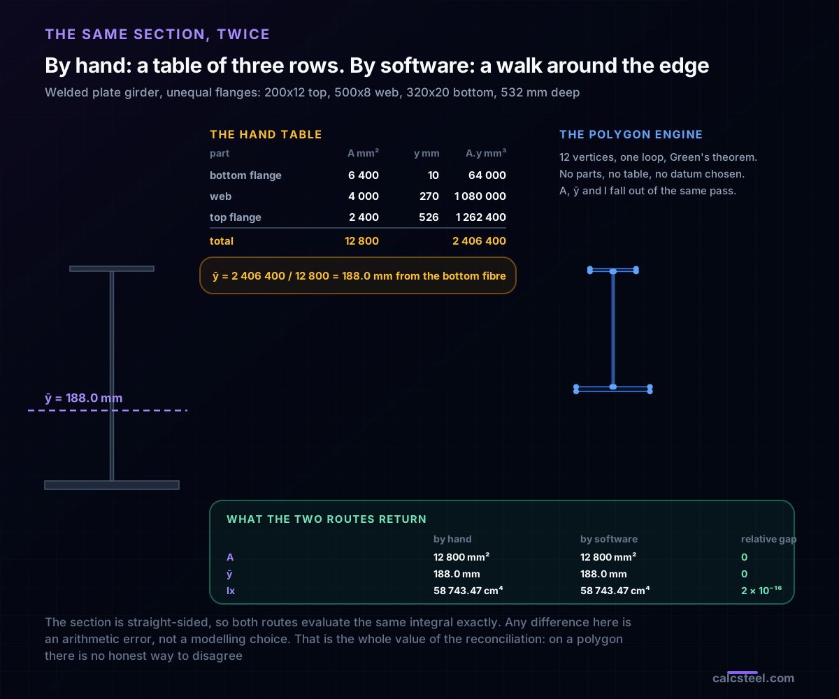
The worked section is a welded plate girder with unequal flanges: a 200 x 12 top flange, a 500 x 8 web, a 320 x 20 bottom flange, 532 mm deep overall. The flanges are deliberately different, because a symmetric section hides the centroid at mid depth and hiding the centroid is exactly what this article is against.
Pick a datum. Any datum, and the bottom fibre is the usual one. Then write three rows.
The bottom flange is 320 x 20 = 6 400 mm², its own centre sits at 10 mm, so A·y = 64 000 mm³. The web is 8 x 500 = 4 000 mm², centred at 20 + 250 = 270 mm, so A·y = 1 080 000 mm³. The top flange is 200 x 12 = 2 400 mm², centred at 20 + 500 + 6 = 526 mm, so A·y = 1 262 400 mm³.
Add the columns. A = 12 800 mm², ΣA·y = 2 406 400 mm³, and
ȳ = 2 406 400 / 12 800 = 188.0 mm from the bottom fibre.
Mid depth would have said 266.0 mm. The centroid is 78.0 mm lower than the geometric middle, because the bottom flange is wider and thicker and it drags the average down. Everything after this point is built on that 188.0.
The moment of inertia follows from the same table with one more column. Each part contributes its own bh³/12 plus the transfer term A·d², where d is the distance from that part's centre to ȳ: −178.0 mm for the bottom flange, +82.0 mm for the web, +338.0 mm for the top flange. The own terms add to 83 575 466.67 mm⁴, the transfer terms to 503 859 200 mm⁴, and
Ix = 587 434 666.67 mm⁴ = 58 743.47 cm⁴.
Note the proportions: 86 % of this section's stiffness comes from the transfer term, which is to say from how far the metal sits from the centroid. Get ȳ wrong and you have not made a small error in a big number, you have made a big error in the term that dominates.
By software: one loop around the edge
The engine does not see three parts. It sees a closed list of vertices, in this case twelve of them, and it never asks you to choose a datum or to decompose anything.
What it runs is Green's theorem, which converts an integral over an area into an integral around the boundary of that area. Walk the twelve edges once, accumulate a cross product per edge, and A, ∫y dA and ∫y² dA all fall out of the same pass. Then divide for the centroid and apply one parallel-axis transfer for the second moments. There is no mesh, no numerical integration and no tolerance anywhere in it. This is the algebra in customSection.ts, which is what the calculator embedded further down this page executes in your browser.
Run both routes on the girder and put the answers side by side.
Area: 12 800 mm² by hand, 12 800 mm² by software. Centroid: 188.0 mm by hand, 188.0 mm by software. Second moment: 58 743.47 cm⁴ by hand, 58 743.47 cm⁴ by software, with a relative gap of 2 × 10⁻¹⁶, which is one floating point rounding step and nothing else.
That agreement is not a coincidence and it is not a validation of anything clever. The section has straight sides, so the hand sum and the boundary integral are the same integral written twice. Which means any real difference between them, on a polygon, is an arithmetic error and not a modelling choice. That is worth saying plainly, because it makes the hand check useful: on a plate girder, if your number and the software's number disagree in the third digit, one of you is simply wrong, and the discussion is short.
The one-line audit: the first moment about the centroid is zero
There is a test that catches a wrong centroid without recomputing anything, and it takes one line.
By definition, ∫ (y − ȳ) dA over the whole section is zero. So if you have a centroid and a decomposition, form Σ Aᵢ (yᵢ − ȳ) and look at it. On the worked girder the three terms are −1 139 200, +328 000 and +811 200 mm³, and they sum to exactly 0.
What makes this useful is that it is invariant. The same section was measured from three different datums, and ΣA·y came out as 2 406 400 mm³ from the bottom fibre, −4 403 200 mm³ from the top fibre and −998 400 mm³ from mid depth. The centroid read 188.0 mm, −344.0 mm and −78.0 mm respectively. All three describe the same point on the same steel, and Ix came back as 587 434 666.67 mm⁴ in every case, identical to the last digit.
So when a hand calculation and a piece of software report different values of ȳ, the first question is not who is right. It is from where. A centroid quoted without its datum is not a number, and this is the single most common way two correct calculations appear to contradict each other.
The zero test settles it. Run it on your own decomposition, with your own datum, and if it does not return zero the error is yours regardless of what anybody else got.
Q is not a section property, and the curve shows why
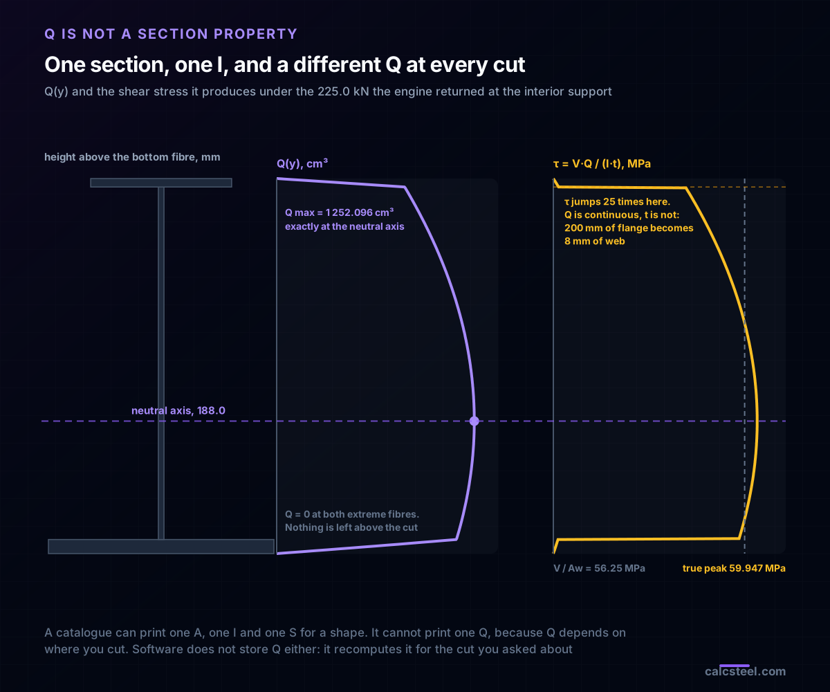
Now cut the girder horizontally and ask for the first moment of everything above the cut, about the centroid. Slide the cut from the bottom fibre to the top and you do not get a number, you get a curve.
At the very bottom fibre there is no area above the cut on one side of the centroid without an equal and opposite area on the other, and Q is exactly 0. At the very top fibre there is nothing left above the cut at all, and Q is exactly 0 again. In between it rises to a single maximum, and that maximum sits precisely at the neutral axis: Q max = 1 252.096 cm³ at y = 188.0 mm, which is where the (y − ȳ) weighting changes sign and stops subtracting.
Take a cut anywhere else and you get a different number. At the top of the bottom flange, y = 20 mm, Q = 1 139.2 cm³. At the underside of the top flange, y = 520 mm, Q = 811.2 cm³. Same section, same steel, three cuts, three answers, all of them correct.
These were computed twice and on purpose by two routines that share no algebra: the closed form band by band, and brute-force midpoint strips, 40 000 per band. The largest disagreement over the whole depth was 5 × 10⁻¹⁰ mm³ against values of order 10⁶.
Which brings back the point from the definitions. Software does not store Q any more than a catalogue prints it, because there is nothing to store. It recomputes Q for the cut you asked about, every time you ask.
Where Q shows up: τ = VQ/(It), and the jump nobody expects
Q earns its keep in one formula, and it is the one that turns a shear force into a stress:
τ = V Q / (I t)
The V here is real. The girder was put into a two-span continuous beam, 9.0 m per span, 40 kN/m, 72 elements, and solved on the finite element engine. At the interior support it returned 225.0 kN of shear and 405.0 kN·m of hogging moment, against the textbook 0.625 w L = 225.0 kN and w L² / 8 = 405.0 kN·m. The engine and the closed form agree to zero relative error, which is the calibration that licenses everything after it.
Feed that through. At the neutral axis, Q = 1 252 096 mm³, I = 587 434 667 mm⁴ and t = 8 mm, so τ max = 59.947 MPa. Against fy/√3 = 204.959 MPa for S355 that is a utilisation of 0.2925, comfortable.
The familiar shortcut τ = V/Aw gives 225 000 / (500 × 8) = 56.25 MPa, low by a factor of 1.0657. Over the full depth instead of the clear web it gives 52.87 MPa, low by 1.1339. On a deep girder the shortcut is close enough to design with, and knowing how close is the point of computing Q at all.
Then look at the flange junctions, because that is where the formula does something that surprises people. Q is continuous across the junction: it is an integral of area, and no area appears or disappears at a line. The thickness t is not continuous. At y = 520 mm the width goes from 200 mm of flange to 8 mm of web, so within the thickness of a weld the stress goes from 1.55 MPa to 38.84 MPa. That is a jump by a factor of exactly 25, which is 200/8. At the bottom junction the same thing happens by a factor of 40, which is 320/8.
Nothing physical is discontinuous there. The elementary theory is, because it assumes the shear stress is uniform across the width at any height, and at a junction that assumption breaks. The jump is a signal that you are reading a one-dimensional theory at the one place it does not hold.
The legitimate disagreement: three rectangles are not an IPE 400
Now the second case, and the one where hand and software differ without either being wrong.
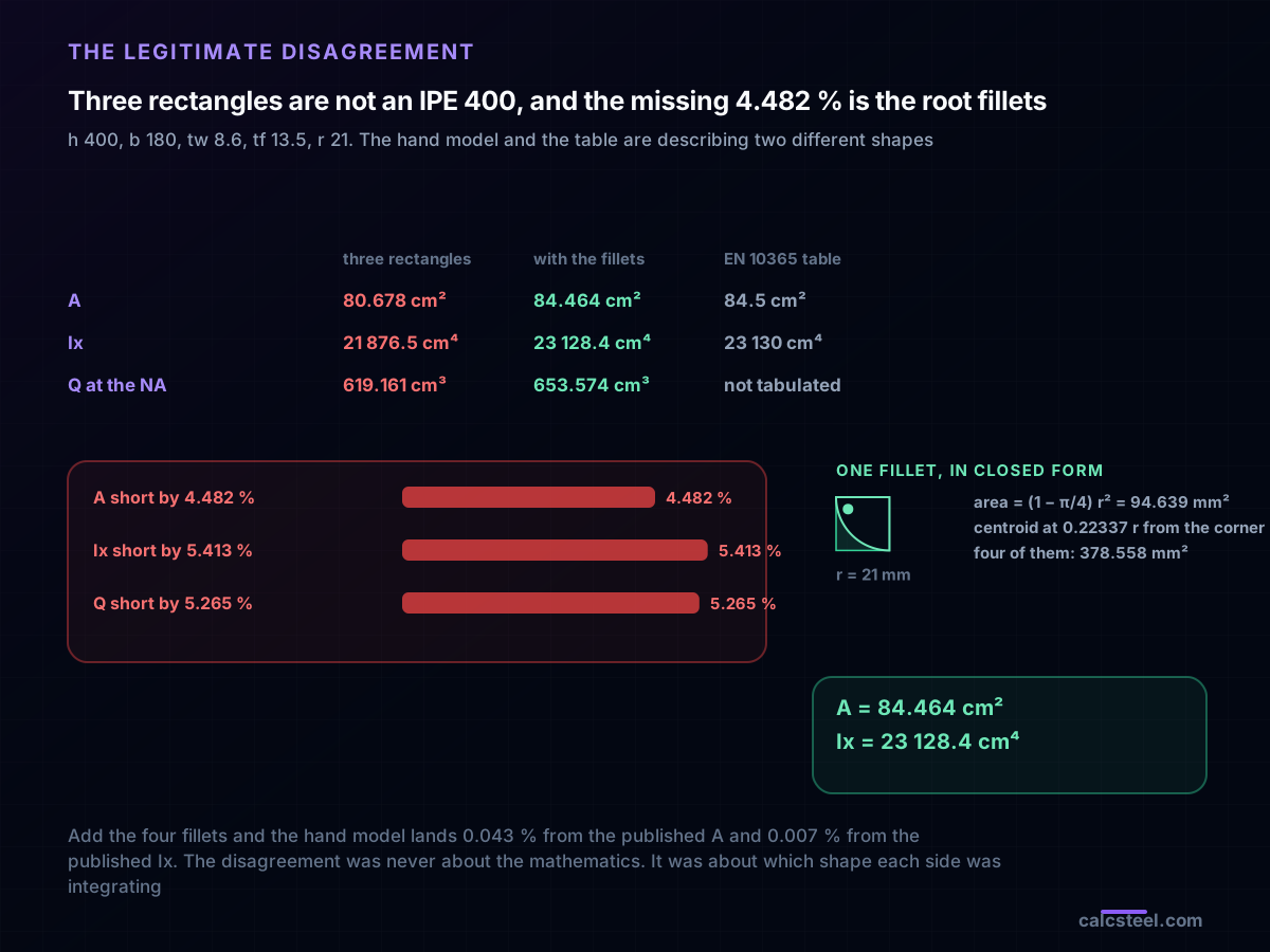
Model an IPE 400 the way everyone first models it: two flange rectangles and a web rectangle. h = 400, b = 180, tw = 8.6, tf = 13.5. That gives A = 80.678 cm², Ix = 21 876.5 cm⁴ and Q at the neutral axis = 619.161 cm³.
The published EN 10365 table says A = 84.5 cm² and Ix = 23 130 cm⁴. The hand model is 4.482 % low on area and 5.413 % low on Ix. That is not rounding.
The missing steel is the four root fillets, the curved transitions where each flange meets the web, and on an IPE 400 the root radius is r = 21 mm. One fillet is the region between a square corner and a quarter circle, so its area is (1 − π/4) r² = 94.639 mm², and its centroid sits at (10 − 3π)/(12 − 3π) = 0.22337 of the radius from the corner, which is 4.691 mm. Four of them are 378.558 mm² of steel, sitting almost as far from the neutral axis as the flanges do.
Add them in closed form, transfer term included, and the hand model returns A = 84.464 cm² and Ix = 23 128.4 cm⁴. That is 0.043 % from the published area and 0.007 % from the published Ix. The first moment moves too: Q at the neutral axis goes from 619.161 cm³ to 653.574 cm³, a 5.265 % correction that lands straight on the shear stress.
So the disagreement was never mathematical. Both sides integrated correctly. They integrated two different shapes, and only one of those shapes is what gets rolled. Before you argue about a section property, agree on the outline.
The practical rule: for a rolled shape, take the catalogue values. They come from the real profile geometry and they are what the code was calibrated against. Use the three-rectangle model for intuition, for a first pass, and for checking that the catalogue value is the right order of magnitude, which it will be to within about 5 %.
What software does with a curve
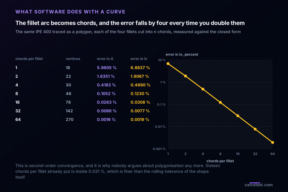
Green's theorem needs edges. A fillet is an arc, and an arc is not an edge, so something has to give. What gives is the arc: the engine replaces it with a chain of straight chords and integrates the polygon exactly.
The question is how many chords. Trace the same IPE 400 as a polygon and cut each of the four fillets into n chords, then measure against the closed form above.
With one chord per fillet, 18 vertices in total, the area is off by 5.961 % and Ix by 6.884 %. With two chords, 1.635 % and 1.907 %. Four chords, 0.418 % and 0.489 %. Eight, 0.105 % and 0.123 %. Sixteen, 0.026 % and 0.031 %. Thirty-two, 0.007 % and 0.008 %. Sixty-four chords, 270 vertices, 0.002 % on both.
The error falls by a factor of four every time the chord count doubles. That is second-order convergence, the signature of a chord approximation to a smooth curve, and it plots as a straight line on log axes.
It also settles a question worth settling: sixteen chords per fillet already put Ix inside 0.031 %, which is far finer than the rolling tolerance of the beam itself. Polygonisation stopped being a source of engineering error a long time ago, and it is not where you should look when two programs disagree.
Moving the centroid on purpose: a cover plate
Everything so far has treated the centroid as something you find. It is also something you move, and a cover plate is the cheapest lever there is.
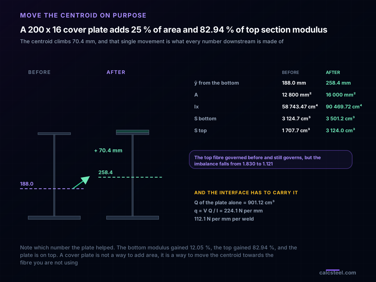
Weld a 200 x 16 plate onto the top flange of the girder. That is 3 200 mm² of steel, a 25 % increase in area, and the composite table now has four rows instead of three. The polygon has sixteen vertices instead of twelve. Both routes agree again, exactly.
The centroid climbs from 188.0 mm to 258.4 mm, a shift of 70.4 mm, and Ix goes from 58 743.47 cm⁴ to 90 469.72 cm⁴, up 54.01 %. Twenty-five per cent more steel bought fifty-four per cent more stiffness, which is the parallel-axis term doing what it always does.
But look at what happened to the section moduli, because that is the number that sizes the beam. The bottom modulus went from 3 124.7 cm³ to 3 501.2 cm³, up 12.05 %. The top modulus went from 1 707.7 cm³ to 3 124.0 cm³, up 82.94 %. The plate is on top, and the top fibre is the one it helped, by nearly seven times as much.
That is the design idea. On a section with unequal flanges the two fibres do not share the load: before the plate, the ratio of the two distances to the centroid was 1.830, so the top fibre reached its limit while the bottom fibre was still loafing. After the plate the ratio is 1.121, and the two fibres are nearly balanced. A cover plate is not a way to add area. It is a way to move the centroid towards the fibre you were not using.
The interface has to carry the change. The first moment of the plate alone, about the new centroid, is 901.12 cm³, so the shear flow at the weld line is q = V Q / I = 224.1 N per mm, or 112.1 N per mm on each of the two fillet welds. Against EN 1993-1-8, with fu = 490 MPa, βw = 0.9 and γM2 = 1.25, the design shear strength on the throat is 251.5 MPa, so the throat needed is 0.446 mm and the leg 0.63 mm. AISC 360 J2 with an E70 electrode asks for a 0.734 mm leg. Both are far below any weld you can actually deposit, so the minimum-size rule governs and a 4 mm fillet is the answer. Compute it anyway: the day the shear is four times larger, the arithmetic is already set up.
Try it: type in a section and read the centroid
The calculator below runs the same polygon routine described above. Give it a rolled shape and it returns the catalogue geometry; give it a custom section and it walks your vertices and returns A, the centroid, Ix, Iy and the product of inertia from one pass around the outline.
The useful exercise is the one this article just did. Enter the worked girder: a 200 x 12 top flange, a 500 x 8 web, a 320 x 20 bottom flange. Check that the centroid comes back at 188.0 mm from the bottom fibre and Ix at 58 743.47 cm⁴. Then add the 200 x 16 cover plate and watch the centroid climb to 258.4 mm.
Do the hand table first, on paper, before you look. The reconciliation is worth more than either number on its own.
Formula — hover a variable to highlight it on the drawing
Ix = [ b·h³ − (b − tw)·hw³ ] / 12= 1,845.6 cm⁴(hw = h − 2·tf)
Iy = [ 2·tf·b³ + hw·tw³ ] / 12= 141.9 cm⁴
Root fillets are neglected — rolled-section tables run 1–5% higher on Ix.
Parallel-axis theorem, live — Ix = Σ ( I₀ + A·d² )
| Part | A (cm²) | d (cm) | I₀ (cm⁴) | A·d² (cm⁴) | I₀ + A·d² (cm⁴) |
|---|---|---|---|---|---|
| Web | 10.25 | 0 | 286 | 0 | 286 |
| Flange (top) | 8.5 | 9.58 | 0.512 | 779.3 | 779.8 |
| Flange (bottom) | 8.5 | 9.58 | 0.512 | 779.3 | 779.8 |
| Σ = Ix | 287 | 1,558.6 | 1,845.6 |
Exact rectangle parts (web + two flanges) about the section centroid — the flange A·d² transfer terms are the whole story of the I-beam. Change any dimension above and watch the table re-derive.
Section properties
Moment of inertia Ix
1,845.6 cm⁴
1.846 × 10⁷ mm⁴
Moment of inertia Iy
141.9 cm⁴
1.419 × 10⁶ mm⁴
Area A
27.25 cm²
Mass
21.39 kg/m
Section modulus Sx
184.6 cm³
Section modulus Sy
28.39 cm³
Plastic modulus Zx
209.7 cm³
Plastic modulus Zy
43.93 cm³
Radius of gyration rx
8.23 cm
Radius of gyration ry
2.28 cm
Centroid x̄ (from left)
50 mm
Centroid ȳ (from bottom)
100 mm
Local slenderness — NBR 8800 / AISC 360 fingerprint
Flange
λ = b / 2·tf = 5.88
λp = 10.75 · λr = 28.28
Web
λ = hw / tw = 32.68
λp = 106.3 · λr = 161.2
Flexure limits per AISC 360 Table B4.1b (≈ NBR 8800 Annex F), fy = 250 MPa, E = 200 GPa — λp/λr scale with √(E/fy). Compact sections reach the full plastic moment Mp = Z·fy; non-compact and slender elements are capped by local buckling.
Closest standard profiles — matched by Ix against 876 real catalog sections
Ix = 1,845.6 cm⁴ (-0.0%)
Iy = 141.9 cm⁴ (-0.0%)
21.39 kg/mlightest
Best match — design checks
Ix = 1,844.2 cm⁴ (-0.1%)
Iy = 902.5 cm⁴ (+535.8%)
34.19 kg/m#2 by weight
Design checks
Ix = 1,838.7 cm⁴ (-0.4%)
Iy = 1,838.7 cm⁴ (+1195.4%)
43.96 kg/m#3 by weight
Design checks
Same 1,309-profile database that powers the CalcSteel 3D editor and profile pages — ABNT cold-formed (Ue, U, rounds), AISC (W, HSS, L, Pipe), European (IPE, HEA, HEB, HEM, UPN) and Indian (ISMB/ISMC) series. Opening a match carries your custom section along as the comparison baseline.
Five ways this goes wrong, and how to tell which one you hit
1. Measuring ȳ' from the datum instead of from the centroid. This is the big one. On the worked girder the area above the neutral axis is 5 056 mm² and its own centre sits at 435.646 mm from the bottom fibre, but only 247.646 mm from the centroid. Use the first and Q becomes 2 202 624 mm³ instead of 1 252 096 mm³, a factor of 1.759, and the shear stress reads 105.46 MPa instead of 59.95 MPa. Nothing about 105.46 MPa looks wrong, which is precisely the danger.
2. Worrying about which side of the cut to take. This one is harmless and people lose time on it. The first moment of the area above the cut is +1 252 096 mm³ and of the area below is −1 252 096 mm³. They sum to zero, because that is the zero test again, so their magnitudes are identical and τ = VQ/(It) does not care. Take whichever side has fewer parts.
3. Using a three-rectangle model against a catalogue value. The 4.482 % area gap on an IPE 400 is the root fillets, and it is real. Two different shapes, two correct answers. Decide which shape you meant before you compare.
4. Quoting a centroid without its datum. The same point on the same girder is 188.0 mm, −344.0 mm or −78.0 mm depending on where you measured from, and all three are right. Half the apparent contradictions between a hand check and a model are this.
5. Reading τ at a flange junction as if it were a real stress. The 25-fold jump at y = 520 mm is the elementary theory failing at the one place its assumption does not hold, not a stress concentration you can design against. If a junction stress governs anything, you need a finer model, not a bigger safety factor.
A six-step routine to reconcile any section against any software
1. Agree on the outline first. Fillets in or out. Corner radii in or out. Galvanising and paint out. Most disagreements die here, before any arithmetic.
2. Write the table with an explicit datum, and put the datum in writing next to ȳ. A centroid without a datum is not an answer.
3. Run the zero test. Σ Aᵢ (yᵢ − ȳ) must be zero. One line, no extra data, and it catches a wrong centroid regardless of how you got it.
4. Check the split of Ix. On the worked girder the transfer terms are 86 % of the total. If the own terms dominate in your table, your parts are probably too big or your ȳ is wrong.
5. Compute Q at the cut you actually care about, not at the neutral axis by reflex. The neutral axis gives the peak web stress; a flange junction gives the shear flow into a weld or a bolt group; and those are different numbers on the same section.
6. Sanity-check τ against V/Aw. On a plate girder the exact peak should sit a few per cent above it, 1.0657 here. If your exact value is far off that, you have used the wrong Q, the wrong t, or both.
Two integrals, one division, one subtraction. The centroid and the first moment of area are the least glamorous quantities in structural analysis, and every number that follows them inherits whatever you did to them.
Sources
- 1.EN 10365, hot rolled steel channels, I and H sections: the published dimensions and section properties of the IPE 400 used as the external anchor
- 2.EN 1993-1-1, design of steel structures, general rules: elastic section properties, the shear area of a rolled section and the shear resistance check
- 3.EN 1993-1-8 §4.5.3, fillet welds: the directional method, βw = 0.9 for S355 and γM2 = 1.25, used to size the cover plate weld
- 4.AISC 360, Specification for Structural Steel Buildings, chapter G (shear) and section J2 (welds), for the second route through the same weld check
- 5.Gere and Goodno, Mechanics of Materials: the shear formula τ = VQ/(It), its derivation from horizontal equilibrium, and the assumptions it rests on
- 6.Timoshenko and Goodier, Theory of Elasticity: why the elementary shear formula fails at an abrupt change of width, and what the real stress field does there
- 7.ABNT NBR 8800, Projeto de estruturas de aço e de estruturas mistas de aço e concreto: elastic section properties and the shear check on a built-up girder
- 8.Green's theorem and the shoelace family of formulas, the standard route from an area integral to a walk around a polygon boundary
Try CalcSteel for free
Model, analyze and design steel structures in your browser. No install, no signup.
Open the 3D editor