Material Stress: Why the Same 226.60 MPa Passes in One Steel and Fails in Another, with a Worked Check
Change the steel grade in your model and watch the bending stress. It does not move. One IPE 360, ten different materials from the engine's own catalogue, and the same 226.60 MPa comes back every time, because in a determinate member the stress is what the load and the geometry do, not what the metal is. What the material changes is the verdict: the same fy = 250 MPa passes at 0.997 under NBR 8800 and fails at 1.007 under AISC 360, on the same beam, on the same day. This article separates the two halves of the phrase “material stress” on the shipping CalcSteel engine, and finds the one case where the material really does rewrite the stress.
Key takeaways
- In a statically determinate member the stress does not know what the member is made of. The same IPE 360 was solved ten times with ten materials and returned M = 198.0 kN·m every time, spread 0.000 kN·m, so σ = M/Wel = 226.60 MPa in all ten.
- The material owns the LIMIT, and the limit is a package, not a number: fy, fu, E, the thermal coefficient, the temperature curve, and the partial factor the code attaches to that family.
- Two steels with the identical fy = 250 MPa split on this beam. NBR 8800 allows fy/1.10 = 227.27 MPa and it passes at 0.997. AISC 360 allows 0.90·fy = 225.0 MPa and it fails at 1.007. The whole disagreement is 2.27 MPa of convention.
- E is a convention too. EN 1993-1-1 declares 210 GPa and AISC and NBR declare 200 GPa, so the identical beam deflects 28.26 mm or 29.67 mm, exactly 5.000 % apart, depending on which book you opened.
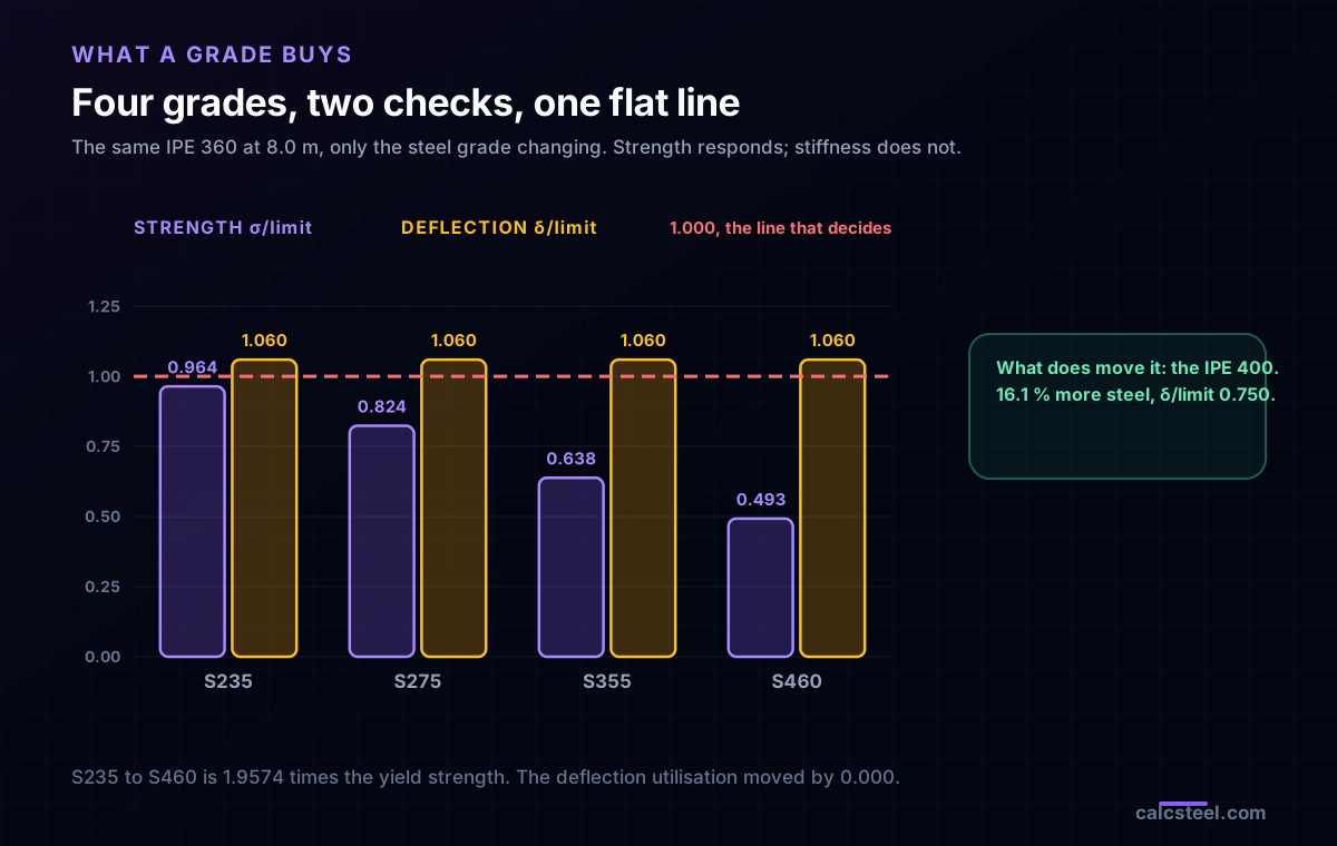
- Upgrading the grade does not touch stiffness. Going from S235 to S460 is 1.9574 times the yield strength: the strength utilisation falls from 0.964 to 0.493 and the deflection utilisation stays at 1.0597, to the last digit. The beam still fails.
- What fixes a stiffness problem is geometry. The IPE 400 is 16.1 % heavier than the IPE 360 and lands at 0.750. The HEA 300 is 54.6 % heavier and only reaches 0.948.
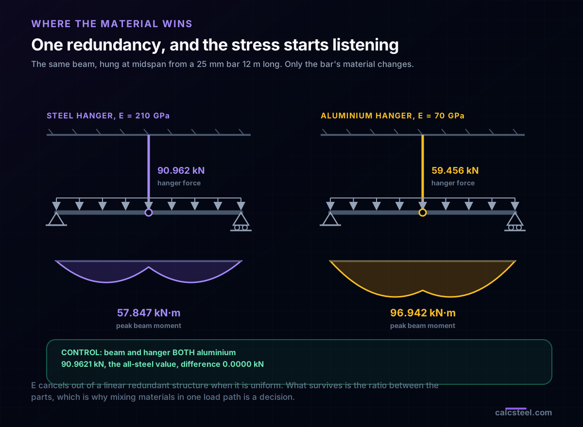
- Redundancy is where the material does change the stress. With a steel hanger at midspan the beam peaks at 57.847 kN·m; swap the hanger for aluminium and the same structure under the same load peaks at 96.942 kN·m, 1.6758 times more, because the split follows the stiffness ratio. Make everything aluminium and the forces return to the all-steel values to the last decimal: it is the ratio that matters, never E alone.
- The material can write stress with no load at all. A 30 K rise on the hanger produces 20.03 MPa with a steel bar and 25.09 MPa with an aluminium one, even though aluminium's fully restrained stress is only 48.3 MPa against steel's 75.6 MPa.
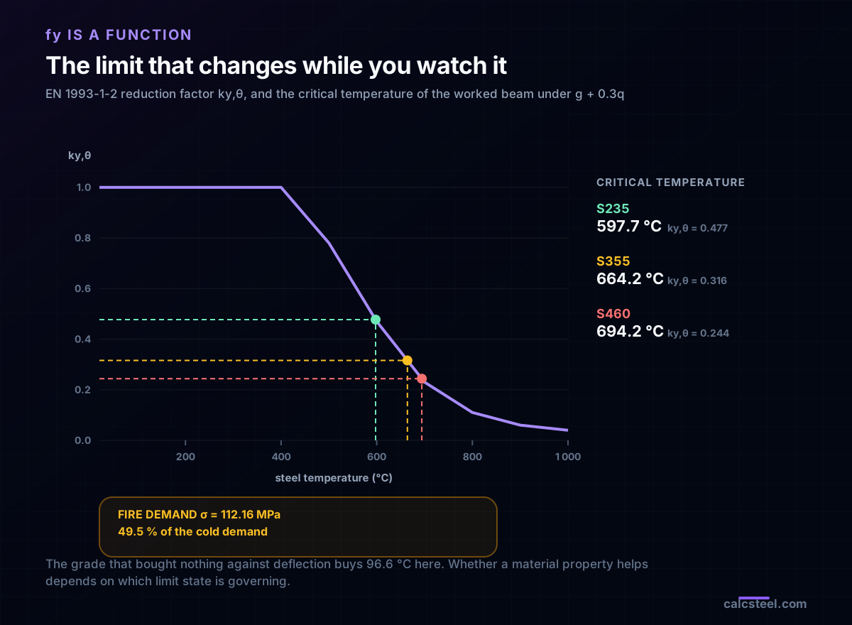
- Above about 400 °C fy is not fy any more. Under the accidental combination this beam runs at 112.16 MPa, and its critical temperature is 597.7 °C in S235 and 694.2 °C in S460. Fire is the one place where paying for a higher grade buys real time.
- Some materials have no yield point to compare against. Austenitic 1.4301 answers with a 0.2 % proof stress, and at the service stress of this beam its secant modulus is 134,005 MPa, 67.0 % of the nominal E, so the real deflection is 44.28 mm and not the 29.67 mm a linear model reports.
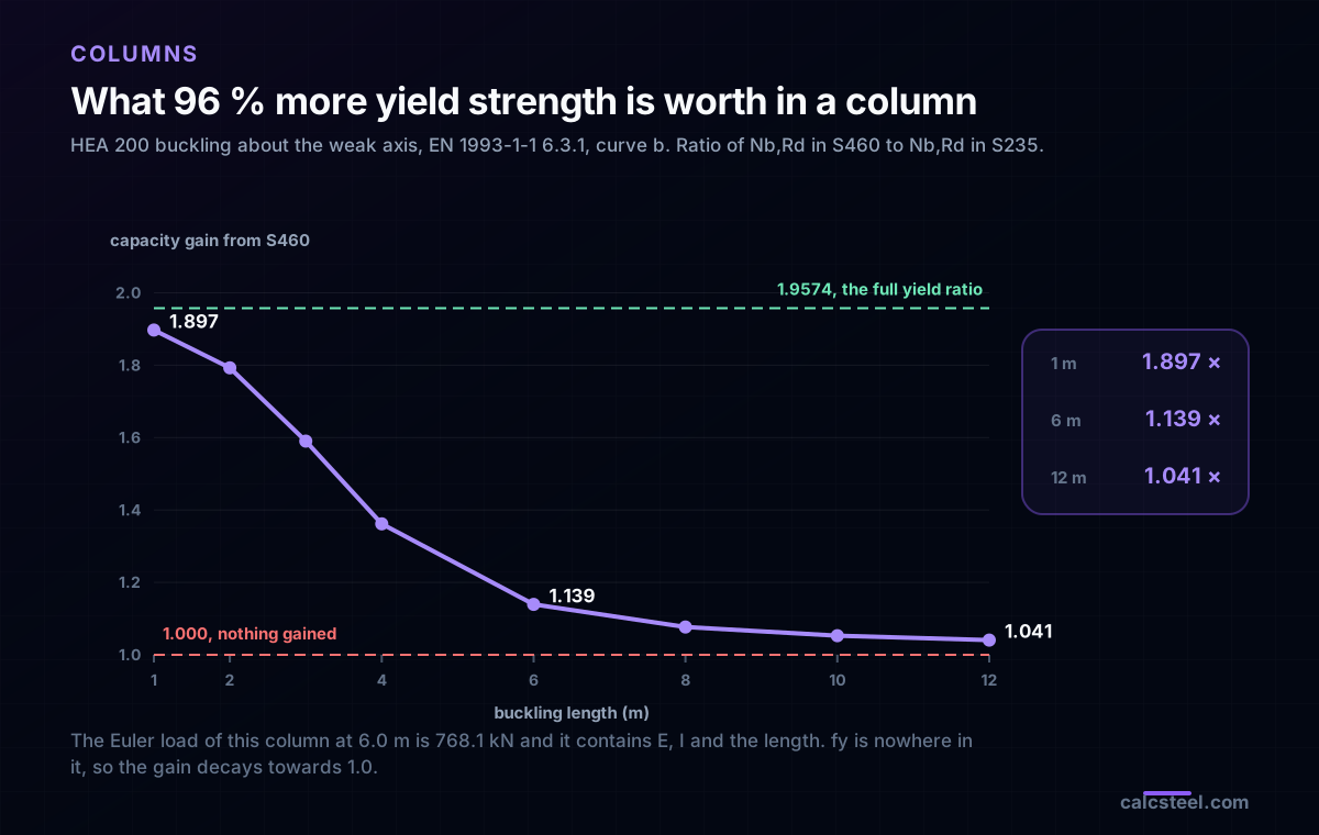
- In a slender column the grade almost stops mattering. On a HEA 200, S460 gives 1.897 times the capacity of S235 at 1 m and only 1.041 times at 12 m, because buckling is governed by E and E is the same in both.
The same beam, passing in one country and failing in another
Here is a beam with nothing interesting about it. An IPE 360, simply supported, 8.0 m of span, carrying 10.0 kN/m of permanent load and 7.5 kN/m of variable load. Composite floors, mezzanines and office bays are full of it.
Run it. The design combination is 1.35 × 10.0 + 1.5 × 7.5 = 24.75 kN/m, the CalcSteel engine returns a peak bending moment of 198.0 kN·m, and against the elastic section modulus of the IPE 360, Wel = 873.77 cm³, that is a bending stress of 226.60 MPa.
Now answer one question: does the beam pass?
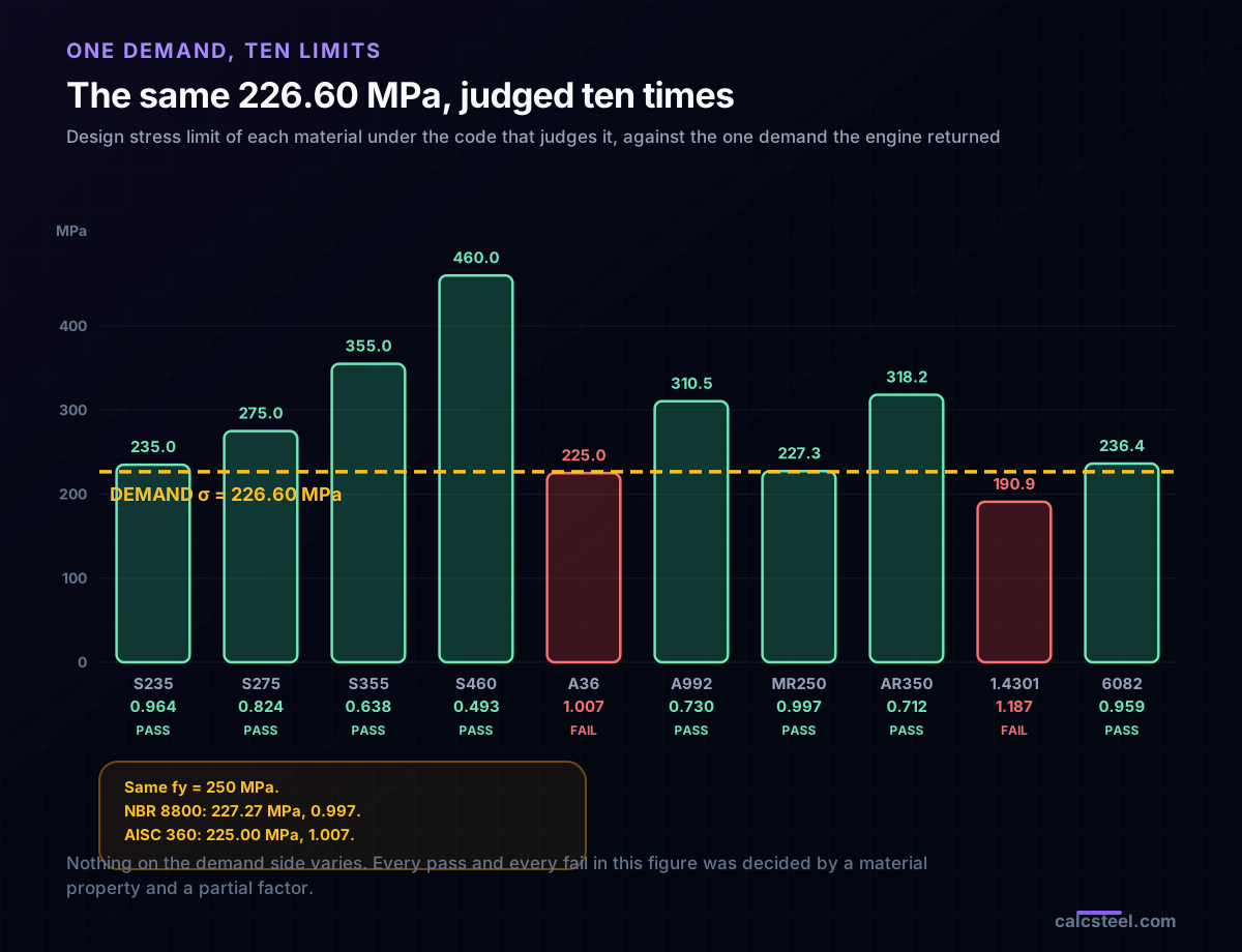
You cannot. Not because the number is uncertain, but because the question is only half asked. In MR250, the ordinary Brazilian structural steel, the screening limit is fy/1.10 = 227.27 MPa and the utilisation is 0.997, a pass. In ASTM A36, which has the exact same yield strength of 250 MPa, the limit is 0.90 × 250 = 225.0 MPa and the utilisation is 1.007, a fail. Same steel. Same beam. Same stress. Opposite verdicts, separated by 2.27 MPa of pure convention.
And in 1.4301 stainless, which most people would call the premium material, the utilisation is 1.187 and the beam is not close. Meanwhile in S460, the strongest steel in the sweep, the bending utilisation drops to 0.493 and the beam still fails, for a reason that has nothing to do with strength.
That is what this article is about. “Material stress” fuses two questions that behave in completely different ways, and every one of the numbers above was produced by the same engine that runs inside CalcSteel, with the material changed and nothing else.
What the phrase actually names
Search “material stress” and you get two different topics wearing one label. One is the stress state: the internal force intensity at a point, in MPa, the thing that σ = N/A and σ = M/W compute. The other is the material limit: the intensity at which that particular metal stops behaving the way the model assumed.
They belong to different owners. The stress state is owned by the load and the geometry. The limit is owned by the material and by the code that judges it. Keeping them apart is not pedantry, it is the difference between two sentences that sound alike and are not:
- “This steel has a stress of 226 MPa.” Meaningless. Steel does not have a stress. A point in a loaded member does.
- “This member is at 226 MPa, and this steel is allowed 225.” A complete engineering statement, and the reason the beam above fails.
There is a real question hiding inside the confusion, though, and it is worth asking properly: does the stress itself depend on the material? The honest answer is that it depends on whether the structure is determinate. In a determinate member, no. In a redundant one, yes, and by a lot. The engine settles both cases below, and the second one is where the modelling errors live.
The worked beam, and what the engine was asked
One model, defined once, solved many times. Only the material identifier on the bars changes between runs.
| Item | Value |
|---|---|
| Section | IPE 360, 57.1 kg/m |
| Span, simply supported | 8.0 m, 40 elements |
| Area, second moment, elastic modulus | A = 72.73 cm², Ix = 15,727.9 cm⁴, Wel = 873.77 cm³ |
| Permanent and variable load | g = 10.0 kN/m, q = 7.5 kN/m |
| Strength combination | 1.35 g + 1.5 q = 24.75 kN/m |
| Serviceability combination | g + q = 17.5 kN/m |
| Deflection limit | L/300 = 26.67 mm |
Before any of it is trusted, the engine has to reproduce the textbook. A calibration run on an IPE 400 at 8.0 m under 30.0 kN/m returned M = 240.0 kN·m against wL²/8 = 240.0, V = 120.0 kN against wL/2 = 120.0, and a midspan deflection of 35.99968 mm against 5wL⁴/384EI = 35.99968 mm. Agreement to five decimal places, so what follows is the model talking, not the solver.
One note on the section properties, because it matters for reproducing these numbers with a steel table in hand. The profile registry builds the shape from the rolled geometry without the root fillets, which gives Wel = 873.77 cm³ where the published table for an IPE 360 says 903.6 cm³, about 3 % higher. Demand and capacity here are computed on the same basis, so every utilisation is consistent, and slightly conservative.
The check itself is the elastic screening the CalcSteel beam calculator runs: σ = M/Wel against the code's design stress. A full verification of a compact section would use the plastic moment and would be more generous. That is deliberate. The point of this article is a comparison between materials, and the elastic route compares them on identical terms.
The engine's answer: ten materials, one stress
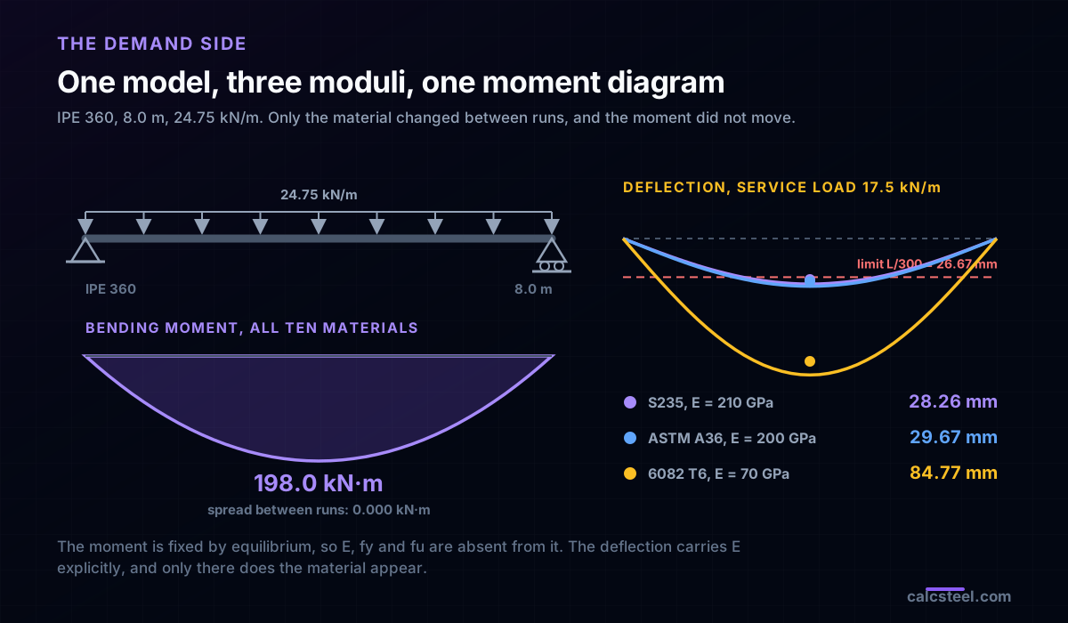
The beam was solved ten times. Structural steels from four traditions, one austenitic stainless and one aluminium alloy, each one carrying the engine's own catalogue values for E, fy, fu and density. The bending moment came back identical in all ten runs: 198.0 kN·m, with a spread between the largest and the smallest of 0.000 kN·m.
That is not a coincidence and it is not a rounding artefact. The beam is statically determinate, so equilibrium alone fixes the internal forces: M = wL²/8 contains the load and the span and nothing else. E, fy, fu and density are simply absent from the equation. So σ = M/Wel = 226.60 MPa in all ten cases, including the aluminium one.
This is the single most useful thing a student can take from a stress chapter, and the least often stated plainly: in a determinate structure the material does not appear in the demand at all. Choosing a stronger steel does not reduce the stress you have to resist. It raises the stress you are allowed to reach.
The deflection is a different story, and the difference is instructive. It carries E explicitly, δ = 5wL⁴/384EI, so it moved in every run where E moved. Under the serviceability combination the same beam came back at 28.26 mm with the European steels at 210 GPa, 29.67 mm with the American and Brazilian steels and the stainless at 200 GPa, and 84.77 mm in aluminium at 70 GPa. The ratio against the steel case is 3.0000, which is 210/70 to four decimals, exactly as the closed form demands.
Look at the first two numbers again, because there is something odd in them. S235 and A36 are, physically, almost the same metal. Their real Young's moduli differ by well under one per cent. But EN 1993-1-1 declares E = 210 GPa and both AISC 360 and NBR 8800 declare E = 200 GPa, and that declaration is what a solver uses. The identical beam therefore deflects 5.000 % more in the American model than in the European one, and no laboratory would find the difference. Part of what we call a material property is a decision written in a committee.
One demand, ten limits, four codes
Here is the whole comparison in one table. The demand column is constant because the previous section proved it has to be. Everything that varies is on the capacity side.
| Material | Code and factor | fy (MPa) | Limit (MPa) | σ/limit | Verdict |
|---|---|---|---|---|---|
| S235 | EN 1993-1-1, γM0 = 1.00 | 235 | 235.00 | 0.964 | pass |
| S275 | EN 1993-1-1, γM0 = 1.00 | 275 | 275.00 | 0.824 | pass |
| S355 | EN 1993-1-1, γM0 = 1.00 | 355 | 355.00 | 0.638 | pass |
| S460 | EN 1993-1-1, γM0 = 1.00 | 460 | 460.00 | 0.493 | pass |
| ASTM A36 | AISC 360, φb = 0.90 | 250 | 225.00 | 1.007 | fail |
| ASTM A992 | AISC 360, φb = 0.90 | 345 | 310.50 | 0.730 | pass |
| MR250 | NBR 8800, γa1 = 1.10 | 250 | 227.27 | 0.997 | pass |
| AR350 | NBR 8800, γa1 = 1.10 | 350 | 318.18 | 0.712 | pass |
| Stainless 1.4301 | EN 1993-1-4, γM0 = 1.10 | 210 | 190.91 | 1.187 | fail |
| Aluminium 6082 T6 | EN 1999-1-1, γM1 = 1.10 | 260 | 236.36 | 0.959 | pass |
Three things in that table are worth more than the rest of the article.
The stainless fails while the mild steel passes. Austenitic 1.4301 costs several times what S235 costs and everybody calls it a better material, which it is, for corrosion. Structurally its 0.2 % proof stress is 210 MPa, below plain S235, and EN 1993-1-4 divides it by 1.10 rather than 1.00. “Better material” is not a structural category. It is only ever better at something specific.
The aluminium passes on strength. With fo = 260 MPa the 6082 T6 profile is allowed 236.36 MPa and lands at 0.959, better than S235. Anyone stopping the check there would ship it. The next section is what happens to that beam.
Two identical yield strengths, opposite verdicts. MR250 and A36 both have fy = 250 MPa, and the codes that judge them disagree by 1.0 %. That deserves its own section.
Same fy, two codes, two answers
MR250 and ASTM A36 are, for this purpose, the same steel: fy = 250 MPa, fu = 400 MPa, E = 200 GPa. The two codes then treat the number differently.
- NBR 8800 divides. The design strength is fy/γa1 with γa1 = 1.10, so 250/1.10 = 227.27 MPa, and 226.60/227.27 = 0.997.
- AISC 360 LRFD multiplies. The design strength is φb·fy with φb = 0.90, so 0.90 × 250 = 225.00 MPa, and 226.60/225.00 = 1.007.
The gap is 2.27 MPa, or 1.01 %, and it is the entire difference between a beam you detail and a beam you resize. It is not a disagreement about steel. 1/1.10 = 0.909 and 0.90 are two roundings of the same reliability target, calibrated against different load factor sets by different committees in different decades. Neither is more correct.
Which is exactly why the CalcSteel beam calculator prints both utilisations side by side on every solve instead of picking one. When a member lands in the 0.99 to 1.01 band, the governing code is not a detail of the report, it is the answer.
The practical rule that follows is short. A utilisation is only a number next to the code that produced it. Copying 0.997 out of a Brazilian job into an American one is not a units conversion, and the beam does not know it moved.
The limit that no grade will move
Return to the beam that fails. The instinct of every engineer under time pressure is to upgrade the steel, so let us do exactly that and measure what it buys.
S235 to S460 is 1.9574 times the yield strength, the largest jump the European catalogue offers in ordinary construction. The strength utilisation falls from 0.964 to 0.493, cut almost in half, and it feels like a solved problem.
The deflection under the serviceability combination is 28.26 mm in S235. In S460 it is 28.26 mm. Not approximately: the engine returned a spread of exactly 0.000 mm across S235, S275, S355 and S460, because all four have the same E = 210 GPa. Against the L/300 limit of 26.67 mm, the utilisation is 1.0597 before the upgrade and 1.0597 after it.
The beam fails identically in the strongest steel available. Not marginally better, not slightly worse. Identically, to the last digit the solver carries.
The reason is one line long. Deflection depends on E and I, and the grade changes neither. Yield strength is a chemistry and processing outcome; Young's modulus is set by the interatomic bond stiffness of iron and is essentially the same in every carbon steel ever rolled. You buy strength with grade. You buy stiffness with shape.
Which is why so many real floor beams are governed by serviceability. The moment you are in that regime, the grade column of the catalogue stops being useful, and the money you spend there buys nothing at all.
What actually fixes it: geometry
If the material cannot fix a stiffness problem, the section has to. Same span, same loads, same S235, only the profile changes.
| Section | Mass (kg/m) | Ix (cm⁴) | δ (mm) | δ/limit | σ/fy |
|---|---|---|---|---|---|
| IPE 360 | 57.1 | 15,727.9 | 28.26 | 1.060 | 0.964 |
| IPE 400 | 66.3 | 22,222.4 | 20.00 | 0.750 | 0.758 |
| IPE 450 | 77.6 | 32,578.3 | 13.64 | 0.512 | 0.582 |
| HEA 300 | 88.3 | 17,578.4 | 25.28 | 0.948 | 0.695 |
The IPE 400 costs 16.1 % more steel than the IPE 360 and takes the deflection utilisation from 1.060 to 0.750. Problem closed, in the cheapest possible currency.
The HEA 300 is the instructive failure. It weighs 54.6 % more than the IPE 360, 33 % more than the IPE 400, and still ends at 0.948, worse than the lighter IPE. All that extra metal went into flange width, which serves stability and column work, not into depth, which is what a second moment of area is made of. Ix scales with the cube of the depth. Nothing else in the catalogue comes close to that leverage.
Two sentences to keep, then, and they are the practical core of the whole topic: a strength problem is a material problem, and a stiffness problem is a geometry problem. Diagnose which one you have before you spend money, because the two remedies do not substitute for each other in either direction.
Run it yourself below. Change fy and watch only the strength utilisation move. Change the profile and watch both move. The calculator prints the NBR 8800 and AISC 360 screenings side by side, which is the 2.27 MPa argument from three sections ago, live.
Max moment
45 kN·m
Max shear
30 kN
Max deflection
10.55 mm
= L/569
Bending stress σ
84.4 MPa
σ = M/Sx
Utilization
44.0%
NBR 8800 · δ ≤ L/250
Geometry & supports
Section
Ix 7999 cm⁴ · Sx 533 cm³ · 42.2 kg/m
Point loads (↓ positive)
None — add as many as you need.
Distributed loads (uniform or trapezoidal)
Model sketch
Diagrams — free PNG / SVG / CSV export, no watermark
Step-by-step — the calculation memory of YOUR beam
IPE 300 · L = 6 m · fy = 250 MPa
1. Reactions (equilibrium of the solved FEM model)
ΣFy = 0 · ΣM = 0
R_A = 30 kN · R_B = 30 kN
2. Peak shear (read from the SFD)
Vmax = |V(x)|max
Vmax = -30 kN @ x = 6 m
3. Peak moment (read from the BMD)
Mmax = |M(x)|max
Mmax = 45 kN·m @ x = 3 m
4. Peak deflection
EI = 15998 kN·m² (E = 200 GPa)
δmax = 10.55 mm @ x = 3 m = L/569
5. Elastic bending stress
σ = Mmax / Sx = 45.00 × 10³ / 533.3
σ = 84.4 MPa
6. Bending check — both codes, side by side
NBR 8800: σ ≤ fy/1.10 = 227.3 MPa · AISC 360: σ ≤ 0.90·fy = 225 MPa
NBR 37.1% PASS · AISC 37.5% PASS
7. Deflection check (serviceability — code-independent)
δ ≤ L/250 = 24 mm
10.55 mm / 24 mm = 44.0% PASS
Recomputed live from the current inputs by the direct-stiffness FEM engine — change any load and every step updates. Reproduce it by hand with the formulas in the sections below.
Lightest catalog profiles that pass (974 flexural candidates · NBR 8800)
| Profile | Std | Weight | Total steel | σ util | δ util | |
|---|---|---|---|---|---|---|
| W310x21 | AISC | 21 kg/m | 126 kg | 83% | 98% | |
| VS 300x23 | BR | 22.6 kg/m | 136 kg | 71% | 84% | |
| U 300x90x6.3 | BR | 23.1 kg/m | 139 kg | 82% | 98% | |
| U 300x100x6.3 | BR | 24.1 kg/m | 145 kg | 77% | 91% | |
| VS 250x25 | BR | 24.6 kg/m | 148 kg | 70% | 100% |
Elastic bending (σ = M/Sx vs fy/γa1, γa1 = 1.10 — NBR 8800) + deflection screening of the full flexural catalog. Lateral-torsional buckling, shear and local buckling are NOT checked here — run the full NBR 8800 / AISC 360 verification in the 3D editor.
The one case where the material does change the stress
Everything so far rested on the beam being statically determinate. Remove that and the conclusion inverts.
Take the same IPE 360 in S355 and hang its midspan from a 25 mm round bar that rises 12 m to a fixed point overhead, the way a floor beam is picked up by a roof truss in an industrial building. That is one degree of redundancy. Equilibrium no longer determines the split between the two load paths: compatibility does, and compatibility is written in stiffnesses.
| Hanger material | E (GPa) | Hanger stiffness (kN/mm) | Hanger force (kN) | Peak beam moment (kN·m) |
|---|---|---|---|---|
| S355 bar | 210 | 8.590 | 90.962 | 57.847 |
| A36 bar | 200 | 8.181 | 89.773 | 59.155 |
| 1.4301 bar | 200 | 8.181 | 89.773 | 59.155 |
| 6082 T6 bar | 70 | 2.863 | 59.456 | 96.942 |
Swapping the hanger from steel to aluminium, and touching nothing else, moves the peak moment in the beam from 57.847 kN·m to 96.942 kN·m. That is 1.6758 times more bending, and the beam's bending stress goes from 66.2 MPa to 110.9 MPa. The load did not change. The geometry did not change. Only what the hanger is made of changed, and the stress in a member 12 m away moved by 68 %.
Each engine result was checked against the compatibility closed form R = δ₀/(L³/48EI + Lh/EhAh), where δ₀ = 39.965 mm is the free midspan deflection of the unpropped beam. Steel: 90.962 kN from the engine against 90.962 kN by hand. Aluminium: 59.456 against 59.456.
Now the control that stops the wrong lesson being learned. Solve it again with the beam and the hanger both in aluminium: the hanger force comes back at 90.9621 kN, and the all-steel case was 90.9621 kN. A difference of 0.0000 kN.
So a soft material does not attract less load. A relatively soft one does. E cancels out of a linear redundant structure whenever it is uniform, and only the ratio between the parts survives. That is why mixing materials in one load path is a decision and not a detail: steel ties on aluminium frames, stainless hangers on carbon frames, timber on steel. The stiffer partner takes the load, and it takes it in proportion to a ratio nobody wrote in the specification.
Stress with no load at all
Stay with the propped beam and delete the loads. Every load case is empty. Now raise the temperature of the hanger by 30 K, which is a sunny afternoon on an exposed member.
The bar wants to grow by α·ΔT·L. The structure will not let it grow freely, and the part of the growth that is prevented becomes force. Applied to the engine as the equivalent thermal load, N₀ = E·A·α·ΔT, and checked against N = -N₀·kbeam/(kbeam + khanger):
| Hanger | α (1/K) | Fully restrained σ (MPa) | Real force (kN) | Real σ (MPa) |
|---|---|---|---|---|
| S355 bar | 12 × 10⁻⁶ | 75.6 | -9.832 | 20.03 |
| 1.4301 bar | 16 × 10⁻⁶ | 96.0 | -12.938 | 26.36 |
| 6082 T6 bar | 23 × 10⁻⁶ | 48.3 | -12.318 | 25.09 |
Three things here are worth slowing down for.
First, the stress exists with no load in the model. This is as literal as “material stress” ever gets: the number was produced by a material property, α, and by nothing else.
Second, the fully restrained stress E·α·ΔT is a trap. Steel reads 75.6 MPa and aluminium only 48.3 MPa, because aluminium's larger α is more than cancelled by its smaller E. From that column you would conclude the aluminium hanger is the safer choice.
Third, the real answer reverses it. The aluminium bar ends up at 25.09 MPa against the steel bar's 20.03 MPa, 1.2528 times more, because a soft bar in series with a beam of finite stiffness keeps a bigger share of its own thermal load: the restraint ratio kbeam/(kbeam + khanger) is 0.52 for aluminium and 0.26 for steel. Full restraint is a bound, not an estimate, and in a real structure the fraction that survives is decided by the stiffnesses around the member.
The engineering habit that follows is old and reliable. Thermal force lives on redundancy, so if you do not want it, do not build the redundancy: a slotted hole, a sliding bearing or an expansion joint turns the whole table into zeros.
The material limit is not one number
Every check so far compared a stress to fy. The limit that a material actually imposes is a package, and fy is only the entry that governs on a warm day with a static load.
fu, at the sections where a net area governs. Yielding on the gross section is ductile and self-limiting, so it is judged against fy with a mild factor. Rupture through a bolt line is neither, so it is judged against fu with a harsher one, EN 1993-1-1 §6.2.3 pairing A·fy/γM0 with 0.9·Anet·fu/γM2 at γM2 = 1.25. The ratio fu/fy is itself a material property: 1.380 in S355 and 2.476 in 1.4301, which is why stainless connections and carbon connections do not fail in the same order.
Temperature. Above roughly 400 °C, fy stops being fy. EN 1993-1-2 reduces it by ky,θ: 0.78 at 500 °C, 0.47 at 600 °C, 0.23 at 700 °C. Under the accidental combination this beam carries g + 0.3q = 12.25 kN/m, so M = 98.0 kN·m and σ = 112.16 MPa, 49.5 % of its cold demand. The critical temperature is where ky,θ·fy drops to that:
- S235 needs ky,θ = 0.477, reached at 597.7 °C.
- S355 needs ky,θ = 0.316, reached at 664.2 °C.
- S460 needs ky,θ = 0.244, reached at 694.2 °C.
Note what just happened. The grade upgrade that bought exactly nothing against deflection buys almost 100 °C here, and 100 °C of a standard fire curve is real minutes and real millimetres of intumescent paint. Whether a material property helps depends entirely on which limit state you are in.
Cycles. Under fatigue, fy drops out of the check completely. A welded detail in S460 and the same detail in S235 share a detail category and an S-N curve; the stress range decides, and the strongest steel on the site carries no advantage whatsoever. It is the clearest case of a material limit that is not a material strength.
The material with no yield point
There is an assumption buried under every number in this article: that the material is linear up to a yield plateau, so E is a constant and fy is a corner. Carbon steel earns that assumption. Austenitic stainless does not.
A 1.4301 tensile curve rounds over from the very beginning and never shows a plateau. There is no yield point to read, so the codes define one: the 0.2 % proof stress, the stress that leaves 0.002 of permanent strain behind. For 1.4301 that is 210 MPa, and it is a convention with a measurement attached, not a physical corner.
The consequence lands on stiffness, not on strength. EN 1993-1-4 models the curve as ε = σ/E + 0.002(σ/f₀.₂)ⁿ with n ≈ 6 for austenitics, so the secant modulus falls as the stress rises. At this beam's serviceability stress of 160.22 MPa, which is 0.763 of the proof stress, the total strain is 1.1957 × 10⁻³ against an elastic 8.011 × 10⁻⁴. The secant modulus is 134,005 MPa, 67.0 % of the nominal 200 GPa.
Which means the deflection of a stainless beam is not the 29.67 mm a linear solver reports. It is roughly 44.28 mm, 49.2 % more, and this is precisely why EN 1993-1-4 asks for a secant modulus at serviceability instead of the nominal E. A stainless member designed by a linear run and checked against a deflection limit can be wrong by half.
Aluminium alloys behave the same way, for the same reason, and are handled the same way in EN 1999-1-1. The general lesson is worth more than either case: the elastic constants you feed a solver are a model of the material, and models have a validity range. Ask where the range ends before you trust the third decimal.
Columns, where a stronger steel almost stops mattering
One more place the material property behaves nothing like the intuition. A HEA 200 column, buckling about the weak axis, checked with EN 1993-1-1 §6.3.1 on curve b, in S235 and in S460.
| Length (m) | λ̄ (S235) | Nb,Rd S235 (kN) | Nb,Rd S460 (kN) | Gain from S460 |
|---|---|---|---|---|
| 1.0 | 0.214 | 1,258.8 | 2,388.0 | 1.897 |
| 3.0 | 0.642 | 1,031.8 | 1,640.8 | 1.590 |
| 4.0 | 0.856 | 872.4 | 1,188.0 | 1.362 |
| 6.0 | 1.283 | 550.3 | 626.8 | 1.139 |
| 8.0 | 1.711 | 347.9 | 374.6 | 1.077 |
| 12.0 | 2.567 | 168.3 | 175.2 | 1.041 |
At 1 m the stubby column is a squash problem and S460 delivers 1.897 times the capacity, almost the full 1.9574 ratio of the yield strengths. At 12 m it delivers 1.041, so 96 % more yield strength has bought 4 % more column.
The reason is that a slender column is not limited by strength at all. The Euler load of this member at 6.0 m is 768.1 kN and it contains E, I and the length: fy is nowhere in it. The design curve only bends the elastic answer down for imperfections and residual stress. As the member gets more slender the answer converges on Euler, and Euler does not care what grade is stamped on the flange.
So the same catalogue upgrade is a bargain in a short column, a waste in a long one, and precisely nothing in a deflection-governed beam. The material is not good or bad on its own. It is good or bad relative to the limit state that is actually governing, which is a property of the structure, not of the metal.
The two questions, and how to keep them apart
Everything above collapses into a short procedure.
- Compute the stress without thinking about the material. In a determinate member it cannot depend on the material, and that is a check on your model, not an approximation.
- Then ask which limit governs. Strength responds to grade. Stiffness responds only to E and I. Stability responds mostly to E. Fatigue ignores grade completely. Fire responds to grade strongly.
- Read the utilisation together with the code that produced it. The same fy = 250 MPa is 227.27 MPa in NBR 8800 and 225.00 MPa in AISC 360.
- Look for mixed materials in one load path. That is the only place where changing a material rewrites the stress, and this beam's moment moved 1.6758 times when the hanger changed.
- Check whether your elastic constants are still valid. Stainless at 0.763 of proof stress is already at 67.0 % of its nominal modulus, and a linear deflection is then 49.2 % optimistic.
The beam that opened the article is a good place to finish. It was at 226.60 MPa, which passed at 0.997 in Brazil and failed at 1.007 in the United States, was comfortable at 0.493 in S460, and failed all three of those times anyway because it deflected 28.26 mm against a 26.67 mm limit. Its actual answer was never a material. It was an IPE 400.
Sources
- 1.EN 1993-1-1, Eurocode 3: design of steel structures, general rules: §6.2 cross-section resistance, §6.3.1 flexural buckling, and the nominal values of fy and E = 210 GPa
- 2.EN 1993-1-2, structural fire design: Table 3.1, the reduction factor ky,θ for the effective yield strength of carbon steel
- 3.EN 1993-1-4, supplementary rules for stainless steels: the 0.2 % proof stress, γM0 = 1.10 and the secant modulus at serviceability
- 4.EN 1999-1-1, Eurocode 9: design of aluminium structures, material properties of 6082 T6 and the partial factor γM1 = 1.10
- 5.AISC 360, Specification for Structural Steel Buildings: φb = 0.90 for flexure, E = 200 GPa, and the ASTM A36 and A992 material properties
- 6.ABNT NBR 8800, Projeto de estruturas de aço e de estruturas mistas de aço e concreto: γa1 = 1.10, and NBR 7007 for the MR250 and AR350 grades
- 7.Gere and Goodno, Mechanics of Materials: stress as a state at a point, the determinate and indeterminate distinction, and thermal effects in restrained members
- 8.Ramberg and Osgood, Description of Stress Strain Curves by Three Parameters, NACA TN 902, the model EN 1993-1-4 Annex C is built on
Try CalcSteel for free
Model, analyze and design steel structures in your browser. No install, no signup.
Open the 3D editor