Stress in Physics: the Tensor, the Criterion Behind the Code, and a Worked Check
In physics, stress at a point is not a number. It is a second-order tensor with six independent components, and it does not become a single number until you name a plane. The code checks one number. The bridge from six to one is a yield criterion, and for steel that criterion is von Mises. This article builds the full Cauchy tensor at real points of a real bracket whose N, V and M come from the CalcSteel engine, and finds a member the flexural check passes at 87.8 % of yield while the tensor at the web-to-flange junction is already at 94.7 %.
Key takeaways
- Stress is a tensor, not a scalar. At one point of the worked bracket the normal stress on a plane ranges from -28.77 MPa to 320.74 MPa and the shear from 0 to 174.76 MPa, depending only on how you orient the cut. Asking for “the stress” without naming a plane is an incomplete question.
- Rotate the tensor and every component changes, but three combinations do not. For this point I1 = 291.97 MPa, I2 = -9 231.55 MPa² and I3 = 0, unchanged through every rotation tested, while σxx alone swings from 0.00 to 319.32 MPa. A design criterion has to be built out of invariants or it would depend on the draughtsman's axes.
- Yielding does not care about pressure. Add 5 000 MPa of hydrostatic stress to the tensor and the von Mises stress moves by 5.7 × 10⁻¹⁴ MPa. That is why the criterion is written on the deviator, and why it collapses to σvm = √(σ² + 3τ²) for a beam.
- The code IS von Mises in two places, exactly. At the extreme fibre τ = 0, so σvm = |σ| and “σ ≤ fy” is the criterion verbatim. At the neutral axis σ ≈ 0, so σvm = √3 τ and the shear limit fy/√3 = 0.577 fy falls out. AISC's 0.6 Fy is that number rounded up by 3.9 %.
- Between those two points it is a shortcut. On the short bracket the extreme fibre reports 311.82 MPa, utilisation 0.878. The web-to-flange junction, where σ = 291.97 MPa and τ = 96.08 MPa act together, reaches σvm = 336.07 MPa, utilisation 0.947. The worst point in the section is not the one the flexural check looks at.
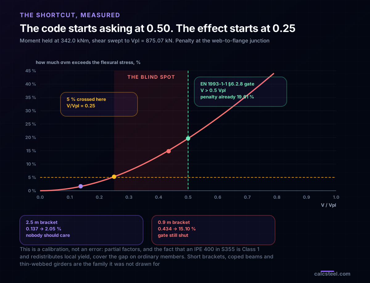
- EN 1993-1-1 asks for the shear interaction only when V > 0.5 Vpl. Here V/Vpl = 0.434, so the gate never opens, yet the true penalty is already 15.10 %. Sweeping the load shows the penalty crosses 5 % at V/Vpl = 0.25, half of where the code starts asking.
- None of this makes ordinary beams wrong. The same bracket at 2.5 m runs at V/Vpl = 0.137 and the tensor correction is 2.05 %, comfortably inside the safety factors. The shortcut is calibrated for the members most people design, and short heavily sheared ones are the edge it was not drawn for.
A bracket that passes at 88 % and is really at 95 %
Here is a member you could design this afternoon. An IPE 400 in S355, cantilevering 0.9 m off a column, carrying 380 kN at the tip and pulled outward by 150 kN. Short, stubby, unremarkable. The kind of bracket that holds a runway beam or a piece of plant.
Run the checks the way everyone runs them. Bending: the root moment is 342.0 kNm, the elastic stress at the extreme fibre is 311.82 MPa against fy = 355 MPa, so the utilisation is 0.878. Shear: 380 kN against a plastic shear resistance of 875.07 kN, utilisation 0.434. Both pass. EN 1993-1-1 only asks you to combine them when the shear exceeds half the shear resistance, and 0.434 is less than 0.5, so there is nothing further to do. The bracket is signed off at 88 % of capacity.
Now go to a point 186.5 mm above the neutral axis, where the web meets the flange, and write down the actual state of stress there. A normal stress of 291.97 MPa and a shear stress of 96.08 MPa, at the same time, on the same particle of steel. Combine them the way physics says you must, and the effective stress is 336.07 MPa. Utilisation 0.947.
Neither check was wrong. The bending stress really is 311.82 MPa and the shear really is below the limit. What went missing is that stress at a point is not one number, and the two checks were reading two different numbers out of the same object. This article is about what that object is, why a criterion is needed to collapse it to one number, where the code is that criterion in disguise, and where it is a shortcut with a measurable blind spot.
The school definition of stress, and what it leaves out
Stress is introduced as force over area, σ = F/A. For a bar pulled along its axis that is complete and correct, and it is why the definition survives so long before anyone notices the hole in it.
The hole is the area. Which area? Cut the same loaded bar with a plane perpendicular to its axis and the force crossing that plane is entirely normal to it: pure tension, no shear. Cut the same bar, at the same point, with a plane at 45 degrees, and the same internal force now has a component along the cut. The material has not changed, the loading has not changed, the point has not changed. Only the question changed, and the answer changed with it.
So the honest definition is local and directional. Take a small area ΔA at a point, with an outward unit normal n. The material on the far side pulls on the near side with a force ΔF. The traction vector is
t(n) = lim(ΔA → 0) ΔF / ΔA
t is a vector, it has three components, and it is a function of n. That last part is the whole story. There is no such thing as “the stress at this point” until you say which plane you are cutting on. There is a stress state, and the traction is what you get when you interrogate that state with a direction.
Note also that t need not point along n. In pure tension it does. In the 45 degree cut it does not, and the part of t along n is the normal stress σn while the part lying in the plane is the shear stress τn. Splitting t that way is the only reason the words normal and shear mean anything.
Cauchy's theorem: nine numbers answer every plane
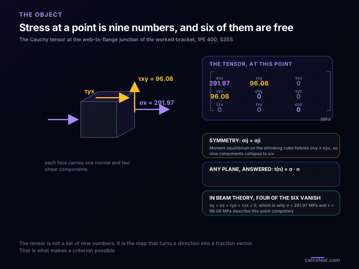
If the traction changes with every plane, and there are infinitely many planes through a point, it looks as though you would need infinitely much information to describe a stress state. Cauchy proved in the 1820s that you need nine numbers, and really only six.
The argument is a free body. Take a tiny tetrahedron at the point with three faces on the coordinate planes and the fourth face cut at an arbitrary normal n. The tractions on the three coordinate faces are known. Write force equilibrium, let the tetrahedron shrink to nothing so the body forces (which scale with volume) vanish against the surface forces (which scale with area), and the traction on the arbitrary face is fixed by the other three:
t(n) = σ · n, that is tᵢ = σᵢⱼ nⱼ
σᵢⱼ is the Cauchy stress tensor. Its first index says which face, the second says which direction the component points. The diagonal terms σxx, σyy, σzz are normal stresses. The off-diagonal terms are shears.
Nine becomes six because of moment equilibrium on the same shrinking cube. If σxy were not equal to σyx, the imbalance would produce a moment that scales with the cube of the size while the resisting inertia scales with the fifth power, so a small enough cube would spin at unbounded angular acceleration. It does not. Therefore σᵢⱼ = σⱼᵢ, the tensor is symmetric, and six numbers describe every plane through the point.
That is the sense in which stress is a tensor rather than a list of nine numbers. A tensor is an object that maps a direction to a vector in a way that does not depend on the axes you happened to write it in, and σ · n is exactly that map.
One point, every plane, swept
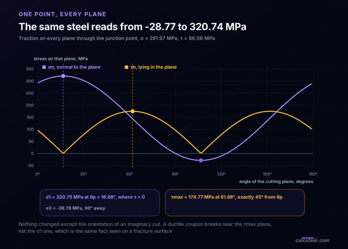
Take the point that matters in the worked bracket, the web-to-flange junction, where the engine and the section give σxx = 291.97 MPa, τxy = 96.08 MPa and everything else zero. Then rotate the cutting plane through 180 degrees, one degree at a time, and evaluate t = σ · n on each.
- The normal stress σn runs from -28.77 MPa to 320.74 MPa. The same particle of steel is in compression on some planes and near yield in tension on others.
- The shear stress τn runs from 0 to 174.76 MPa, and the maximum lands at 62 degrees from the beam axis.
- Where σn is at its maximum, τn is exactly zero, and vice versa. Those two extremes are 45 degrees apart, every time.
Nothing about the material or the loading changed across that sweep. Only the orientation of an imaginary cut. If someone hands you a number and calls it the stress at a point, that number is one sample from this curve, and the useful question is which sample.
It also explains something you can see on any broken tensile coupon. Pull a ductile steel bar and it does not part on the plane where the normal stress is highest. It shears on a plane running roughly 45 degrees across, because that is where the shear stress peaks, and ductile metals fail by sliding, not by pulling apart. The fracture surface is a photograph of this sweep.
What stays still while everything moves
Rotate the axes and the components of the tensor change. That is unavoidable and it is a problem, because a design rule cannot depend on which way somebody drew the grid. Rotating this point's tensor about z by a handful of arbitrary angles gives:
| rotation | σxx | σyy | σxy | von Mises |
|---|---|---|---|---|
| 0° | 291.97 | 0.00 | 96.08 | 336.0679 |
| 13° | 319.32 | -27.34 | 22.36 | 336.0679 |
| 31.7° | 297.26 | -5.29 | -87.51 | 336.0679 |
| 45° | 242.07 | 49.90 | -145.99 | 336.0679 |
| 67° | 113.69 | 178.28 | -171.76 | 336.0679 |
| 90° | 0.00 | 291.97 | -96.08 | 336.0679 |
Every component moves. σxx alone goes from 319.32 MPa down to 0.00 MPa, a swing of the entire stress, purely by turning the paper. The last column does not move at all, to nine decimal places.
The reason is that three particular combinations of the components are invariant under rotation:
I₁ = σxx + σyy + σzz = 291.97 MPa
I₂ = σxxσyy + σyyσzz + σzzσxx - τxy² - τyz² - τzx² = -9 231.55 MPa²
I₃ = det(σ) = 0
They are the trace, the sum of principal minors and the determinant, and they hold at every angle tested here to within one part in a million. Any function built only from I₁, I₂ and I₃ is automatically axis-independent, and that is the raw material every yield criterion is made of.
Principal stresses: the axes the material chooses
Among all the planes swept above there are three, mutually perpendicular, on which the traction is purely normal: the shear vanishes and t points straight along n. Those are the principal planes, their normals are the principal directions, and the normal stresses on them are the principal stresses σ₁ ≥ σ₂ ≥ σ₃. Formally they are the eigenvalues of σ, which is why they exist for any symmetric tensor and why they are invariant.
For a beam state, with σy = σz = 0, the algebra is short:
σ₁,₃ = σ/2 ± √((σ/2)² + τ²), tan 2θp = 2τ/σ
At the junction point: σ₁ = 320.75 MPa, σ₂ = 0, σ₃ = -28.78 MPa, with the principal direction at θp = 16.68 degrees. Notice σ₁ is larger than the 291.97 MPa you started with. Shear does not just add a second stress alongside the normal one, it raises the largest tension in the material above either.
The maximum shear stress follows immediately: τmax = (σ₁ - σ₃)/2 = 174.77 MPa, on planes at θp + 45° = 61.68 degrees. The 180 degree sweep found its peak of 174.76 MPa at 62 degrees, which is the same answer at one degree resolution. Mohr's circle is nothing more than the graph of these formulae, with centre σ/2 and radius √((σ/2)² + τ²).
Tresca's criterion says the material yields when σ₁ - σ₃ reaches fy. Here that difference is 349.53 MPa against 355, so Tresca puts this point at 0.984 of capacity. It is the more conservative of the two criteria by about 4 % in this state, and it is the one most concrete and older steel codes were built on.
Why pressure does not count
Split any stress tensor into two parts. The hydrostatic part is the mean stress σm = I₁/3 times the identity: equal pull or push in all directions, which changes volume but not shape. What is left is the deviator, s = σ - σm I, which changes shape but not volume.
The experimental fact behind every metal plasticity model is that yielding is a deviator phenomenon. Metals yield by dislocations sliding on planes, sliding is driven by shear, and pure pressure produces no shear on any plane. Bridgman won a Nobel Prize partly for showing that steel under enormous hydrostatic pressure yields at the same deviatoric stress as steel at atmospheric pressure.
You can watch that in the arithmetic. Take the junction tensor and add p to all three diagonal terms:
| added p | mean stress | von Mises |
|---|---|---|
| -500 MPa | -402.68 MPa | 336.067928 |
| 0 | 97.32 MPa | 336.067928 |
| +500 MPa | 597.32 MPa | 336.067928 |
| +5 000 MPa | 5 097.32 MPa | 336.067928 |
The mean stress moves over 5 500 MPa. The von Mises stress moves by 5.7 × 10⁻¹⁴ MPa, which is floating-point noise, not physics. So the criterion has to be a function of the deviator alone, and the simplest invariant of the deviator that is not identically zero is its second one, J₂.
That is the whole derivation of von Mises. Yield when J₂ reaches a critical value, calibrate that value against a simple tension test where yield happens at fy, and you get
σvm = √(½[(σ₁-σ₂)² + (σ₂-σ₃)² + (σ₃-σ₁)²]) ≤ fy
and for the beam state, where only σ and τ survive, it collapses to the form you have seen in the code without being told where it came from:
σvm = √(σ² + 3τ²)
The worked check: the member, and where its numbers come from
Everything above is now applied to one member, with nothing assumed that could have been computed.
The structure. An IPE 400 in S355, fixed at one end, cantilevering 0.9 m, with 380 kN applied downward at the tip and 150 kN pulling outward along the axis. Two cases are run: this one, and a longer 2.5 m version carrying 120 kN, to show an ordinary member for contrast.
The engine. The internal forces come from app.engine.solver.run_analysis, the same solver that runs behind CalcSteel. Before trusting it, a control case: a simply supported IPE 400 over 8 m under 30 kN/m must return wL²/8, wL/2 and 5wL⁴/384EI. It returns 240.00 kNm, 120.00 kN and 35.99968 mm against a closed form of 35.999678 mm. The control passes to better than 0.001 %, so the bracket runs. At its root the engine gives N = 150.0 kN, V = 380.0 kN and M = 342.0 kNm, matching H, P and P·L exactly, as a determinate member must.
The section. Stresses need geometry, and the profile registry stores approximations for this shape (its Zx of 655 cm³ is roughly half the true value), so the section is integrated from the real dimensions instead: web, flanges and the four root fillets. That gives A = 8 446.4 mm², I = 23 260 cm⁴, Wel = 1 163.0 cm³ and Wpl = 1 310.7 cm³, against published table values of 8 450 mm², 23 130 cm⁴, 1 156 cm³ and 1 307 cm³. Every one is inside 0.61 %. Because the cantilever is statically determinate, the engine's N, V and M do not depend on this at all.
The field, then checked backwards. Normal stress is σ(y) = N/A + M·y/I and shear is τ(y) = V·Q(y)/(I·t(y)), with Q integrated numerically over the same section. A stress field is only the member's stress field if it integrates back to the member's internal forces, so it is made to prove it:
- ∫σ dA = 150.000 kN against the engine's N = 150.0 kN
- ∫σ·y dA = 342.000 kNm against the engine's M = 342.0 kNm
- ∫τ dA = 380.001 kN against the engine's V = 380.0 kN
All three close to better than 0.001 %. From here the tensor is real, not illustrative.
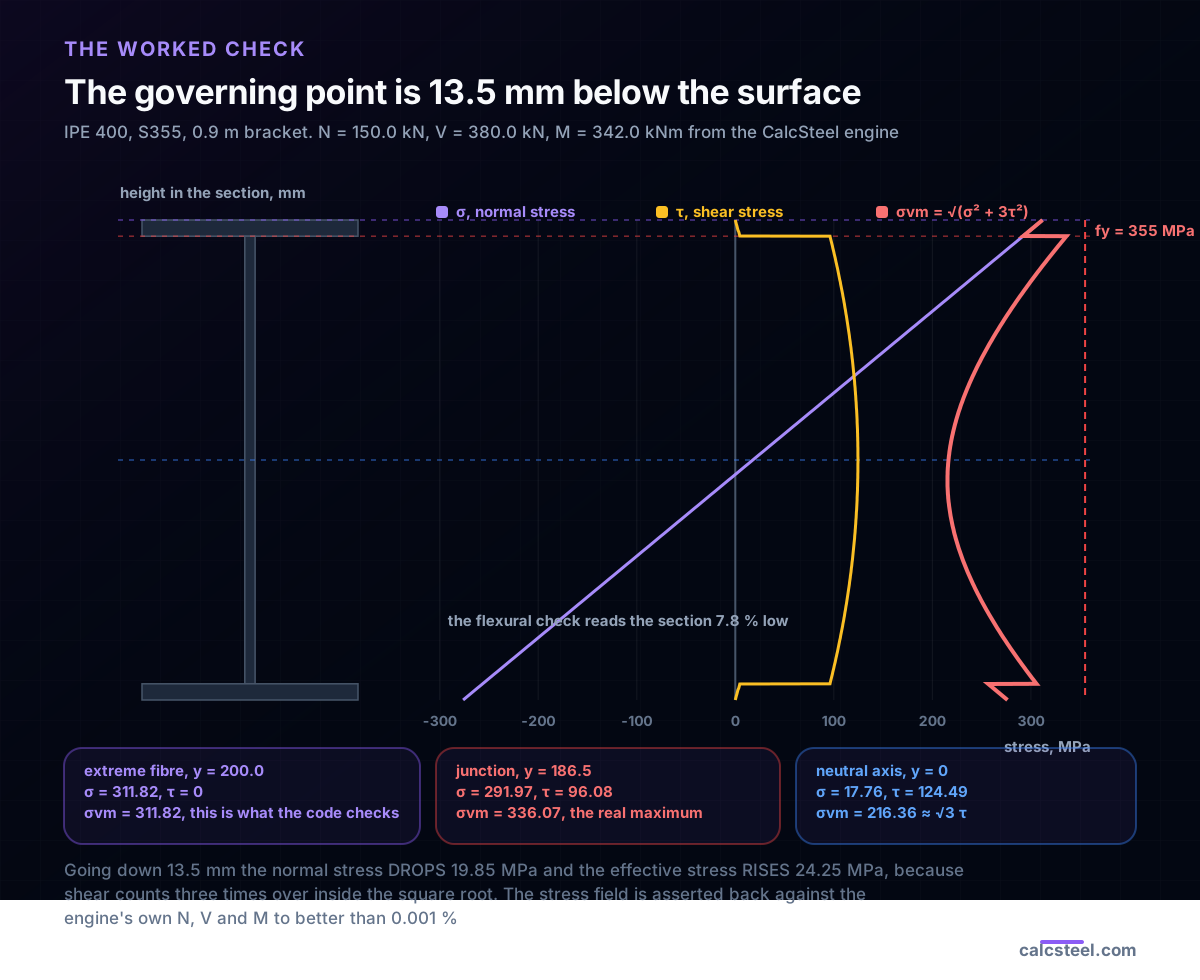
Three points through the depth, and the one that governs
Evaluate the tensor at three heights and run each through the machinery: principal stresses, Tresca, von Mises.
| point | y | σ | τ | σ₁ | σ₃ | σvm | σvm/fy |
|---|---|---|---|---|---|---|---|
| extreme fibre | 200.0 mm | 311.82 | 0.00 | 311.82 | 0.00 | 311.82 | 0.878 |
| web/flange junction | 186.5 mm | 291.97 | 96.08 | 320.75 | -28.78 | 336.07 | 0.947 |
| neutral axis | 0.0 mm | 17.76 | 124.49 | 133.69 | -115.93 | 216.36 | 0.610 |
Read the first row and the second together. Going down 13.5 mm from the surface, the normal stress drops by 19.85 MPa, exactly as the linear bending diagram says it must. And the effective stress rises by 24.25 MPa, because the shear it picks up on the way counts three times over inside √(σ² + 3τ²).
Sweeping the full depth confirms the maximum von Mises stress in the whole section sits at the junction, at 336.07 MPa, and not at the extreme fibre, at 311.82 MPa. The flexural check evaluates the section at precisely the height where the answer is 7.8 % too low.
The neutral axis row is worth its own look. The normal stress there is 17.76 MPa, which is nothing but the 150 kN axial pull spread over the area. Almost the entire effective stress of 216.36 MPa comes from shear, and √3 × 124.49 = 215.62, the rest being the small axial contribution. This is the point where the criterion is pure shear, and the next-to-last section shows the code already knows its answer.
The shear stress that jumps by a factor of 21
One detail at the junction deserves separate attention, because it catches people who compute τ = VQ/It carefully and then read it at the wrong side of a line.
At y = 186.5 mm exactly, the web ends and the flange begins. Q, the first moment of the area beyond the cut, is continuous there: it does not care that the shape is about to get wider. The thickness t is not continuous at all. It jumps from tw = 8.6 mm to b = 180 mm.
Since τ = VQ/(I·t), the shear stress jumps by the ratio of those widths:
- web side of the interface: τ = 96.08 MPa, σvm = 336.07 MPa
- flange side of the interface: τ = 4.59 MPa, σvm = 292.08 MPa
- ratio: 20.93, which is b/tw = 180/8.6 to six decimals
Same height, same Q, same V, two answers 44 MPa apart in effective stress. The web side is the one that governs, and it is the one people skip when they evaluate the flange.
This is also why the classic approximation τ ≈ V/(tw·hw), which spreads the shear uniformly over the web, is as good as it is for rolled I-sections: nearly all the shear really does live in the web, because the flanges are too wide to carry any meaningful stress at the same Q. It is a good approximation for the average and a poor one for the peak, which is the point the criterion cares about.
Try it: put this tensor into the calculator
The fastest way to make this concrete is to type the worked point in and watch the circle. Enter σx = 291.97 MPa, σy = 0 and τxy = 96.08 MPa, which is the junction of the bracket, and you should get σ₁ = 320.75 MPa, σ₃ = -28.78 MPa, θp = 16.68° and τmax = 174.77 MPa.
Then try the two limiting rows from the table. Set τ to zero and leave σ at 311.82: the circle collapses onto the axis, σ₁ = σ and von Mises equals the bending stress, which is the code's flexural check. Set σ to zero and τ to 124.49: the circle centres on the origin, σ₁ = -σ₃ = τ, and von Mises is √3 × τ. Everything the code does to a beam lives between those two extremes.
σ₁ (major)
92.4MPa
σ₂ (minor)
7.6MPa
τmax in-plane
42.4MPa
θp (to σ₁)
22.5°
τabs (3-D)
46.2MPa
von Mises
88.9MPa
η · NBR
0.28 ✓
Plane-stress state (MPa)
Tension positive. τxy positive = shear that tends to rotate the element counter-clockwise on the +x face.
Plane stress (σz = 0). Enable to inspect a genuine triaxial state — three circles, not two.
Code check — steel grade
σvM = 88.9 MPa ≤ 313.6 MPa = fy / γa1 (γa1 = 1.10)
NBR 8800:2008 §5.4.2.2 (γa1 = 1,10)
From your solved model
Solve a model in the CalcSteel 3D editor, then return here to load the real σx/σy/τxy at any member section — Mohr's circle becomes the solver's inspection lens.
Presets
Element rotation θ
0°Export (free · no watermark)
Where the code is von Mises without saying so
None of this is a discovery the codes missed. Two of the most familiar clauses in steel design are the von Mises criterion evaluated at a special point, and recognising that makes them stop being arbitrary.
The flexural check is von Mises at the extreme fibre. At the surface of a beam the shear stress is exactly zero, because there is no material beyond it to shear against, so Q = 0 there. Put τ = 0 into σvm = √(σ² + 3τ²) and you get σvm = |σ|. The rule “σ ≤ fy” is not a simplification of the criterion at that point, it is the criterion at that point, exactly.
The shear limit is von Mises at the neutral axis. In a member with little axial force the normal stress at mid-depth is near zero, so σvm reduces to √3 τ. Setting that equal to fy gives the shear yield stress:
τy = fy/√3 = 0.5774 fy, which for S355 is 204.96 MPa
That is where every 0.577 in the literature comes from, and where EN 1993-1-1's Vpl,Rd = Av·fy/(√3·γM0) comes from directly. AISC 360 writes 0.6 Fy instead, which for S355 is 213.0 MPa, 3.9 % above the pure von Mises value; the difference is absorbed by the resistance factor and the web shear-buckling coefficient Cv that sits alongside it. Tresca, incidentally, would give exactly 0.5 fy, which is why some older references use half the yield stress for shear.
And in one place the code prints it outright. EN 1993-1-1 §6.2.1(5) gives a general conservative check for any point of a cross-section as √(σx² + σz² - σxσz + 3τ²) ≤ fy/γM0. That is the von Mises criterion in plane stress, written into the standard, available to anyone who wants to check the junction point by hand.
Where it is a shortcut, and how big the gap is
Between the extreme fibre and the neutral axis, the code does not evaluate the criterion. It checks bending at the top, shear on the web, and combines them only when the shear is large. EN 1993-1-1 §6.2.8 opens that gate at V > 0.5 Vpl, below which no reduction to the moment resistance is required.
So hold the moment of the worked bracket at 342.0 kNm, sweep the shear from zero to Vpl, and measure how much the junction's true von Mises stress exceeds the normal stress the flexural check sees at that same height:
| V/Vpl | V | penalty at the junction |
|---|---|---|
| 0.137 (the 2.5 m bracket) | 120 kN | 2.05 % |
| 0.25 | 218.8 kN | 5.25 % |
| 0.434 (the 0.9 m bracket) | 380 kN | 15.10 % |
| 0.50 (the code's gate opens) | 437.5 kN | 19.61 % |
The penalty passes 5 % at V/Vpl = 0.25, which is half of where the code starts asking. By the time the gate does open, the effect it is opening for has already reached 19.6 %. That band, between a quarter and a half of Vpl, is the measured size of the shortcut.
Which is not the same as saying the code is unsafe, and it matters to be precise about why:
- The partial factors sit on top of all of this. γM0 = 1.00 in EN and φb = 0.90 in AISC, with load factors of 1.35 and 1.5 underneath, leave far more than 15 % of room in any real design.
- The check is elastic and the section is not. An IPE 400 at S355 is Class 1, so reaching fy at one point 186.5 mm up simply starts a local yield that redistributes into neighbouring fibres. First yield is not failure for a compact rolled shape.
- The members that reach V/Vpl = 0.25 with a high moment at the same section are a small family: short brackets, coped beams, heavily loaded stubs, and plate girders where the web is deliberately thin.
The honest summary is that the separate checks are a calibration, tuned for the members most people design, and the tensor is the thing being approximated. On the ordinary 2.5 m bracket the approximation costs 2.05 % and nobody should care. On the 0.9 m one it costs 15.10 % and it is worth ten minutes with √(σ² + 3τ²) at the junction.
von Mises or Tresca, and why steel codes chose one
Both criteria are invariant, both ignore hydrostatic stress, both reduce to fy in simple tension. They differ in what they say about every other state.
Tresca yields when the maximum shear stress reaches fy/2, that is when σ₁ - σ₃ = fy. Drawn in principal-stress space it is a hexagon. Von Mises is the ellipse circumscribed about it in plane stress, so the two agree exactly at six points and von Mises is never more conservative anywhere.
The widest gap is pure shear, where Tresca yields at 0.500 fy and von Mises at 0.577 fy, a difference of 15.5 %. At the junction point of the worked bracket Tresca gives σ₁ - σ₃ = 349.53 MPa against von Mises 336.07 MPa, so Tresca is 4.0 % more demanding there.
Steel codes chose von Mises for two reasons. It matches thin-walled torsion and combined-loading tests on ductile metals better, typically within a few per cent while Tresca is conservative by up to 15 %. And it is smooth: the hexagon has corners where the yield surface has no unique normal, which makes the plasticity flow rule ambiguous and finite element implementations awkward. Tresca survives where its conservatism is welcome and its algebra is simpler, which is why you still meet it in pressure-vessel work.
Seven things that go wrong
- Quoting a stress without a plane. “The stress at the weld is 180 MPa” is incomplete until the plane is named. On this bracket's junction the same point reads anywhere from -28.77 to 320.74 MPa in normal stress.
- Adding σ and τ arithmetically. They are different components of one object, not two loads on a beam. 291.97 + 96.08 = 388.05 is meaningless; √(291.97² + 3·96.08²) = 336.07 is the answer.
- Checking only the extreme fibre. In this member the governing point is 13.5 mm below the surface, and the flexural check misses it by 7.8 %.
- Reading τ on the flange side of the junction. Same y, same Q, but t jumps from 8.6 to 180 mm and the answer changes by a factor of 20.93. The web value is the governing one.
- Treating 0.5 Vpl as physics. It is a threshold for when the code requires an interaction, not the load at which interaction begins. The interaction has been there the whole time, worth 5 % already at half that shear.
- Expecting hydrostatic stress to matter. A member deep under pressure yields at the same deviatoric stress as one at the surface, to fourteen decimal places in the arithmetic above.
- Using von Mises where it does not apply. It is a ductile-metal criterion. Fatigue, brittle fracture, bolts in shear and concrete each have their own limit state, and none of them are √(σ² + 3τ²) ≤ fy.
The single sentence to carry away: stress in physics is a tensor, the code checks a scalar, and a yield criterion is the exchange rate between them. Knowing where the exchange rate is exact and where it is a rounding tells you which members you can sign in a minute and which ones deserve ten.
Sources
- 1.EN 1993-1-1 §6.2.1(5), the general yield check √(σx² + σz² - σxσz + 3τ²) ≤ fy/γM0; §6.2.6 shear area and Vpl,Rd; §6.2.8 bending and shear interaction above 0.5 Vpl
- 2.AISC 360, Specification for Structural Steel Buildings, chapter G: the shear resistance 0.6 Fy Aw Cv and its relation to fy/√3
- 3.ABNT NBR 8800, Projeto de estruturas de aço e de estruturas mistas de aço e concreto
- 4.Timoshenko and Goodier, Theory of Elasticity (Cauchy's tetrahedron, the stress tensor, principal stresses and the invariants)
- 5.Gere and Goodno, Mechanics of Materials (plane stress, Mohr's circle, and the shear formula τ = VQ/It)
- 6.Hill, The Mathematical Theory of Plasticity (the deviatoric split, J₂ and the derivation of the von Mises and Tresca surfaces)
- 7.Bridgman, Studies in Large Plastic Flow and Fracture (hydrostatic pressure does not change the yield of a ductile metal)
- 8.Euronorm 19-57 / EN 10365 section tables for IPE 400 (A, Ix, Wel, Wpl), the external anchor for the integrated section
Try CalcSteel for free
Model, analyze and design steel structures in your browser. No install, no signup.
Open the 3D editor