The Second Derivative: Curvature, the Elastic Line, and How a Beam Actually Bends
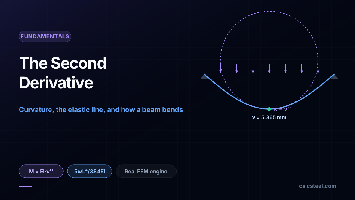
The second derivative you met in Calculus I is not a graphing trick you leave behind after the exam. It is the exact quantity that decides how much a loaded beam bends: the bending moment at any section equals EI times the second derivative of the deflected shape, and that second derivative is the curvature of the elastic line. This guide connects the concavity of a curve from calculus to the sag of a real steel beam, with three worked members computed on the CalcSteel finite-element engine and a live calculator you can drive yourself.
Key takeaways
- The bending moment is the second derivative of the deflected shape times the bending stiffness: M(x) = EI·v''(x). The curvature of the elastic line, v'', carries the moment diagram inside its own concavity.
- This is the third relation in a single calculus ladder. Differentiate the deflection once for the slope, twice for the curvature and moment, three times for the shear, four times for the load. One function, five derivatives.
- On a 6 m simply supported IPE 360 under 10 kN/m, the engine bends the beam to 5.365 mm at midspan, exactly 5wL⁴/384EI, and the midspan curvature is 0.00143 per metre, a bend radius of about 700 m.
- Curvature has the same sign as the moment: positive where the beam sags, negative where it hogs, and zero at a point of inflection, which is exactly where the moment crosses zero.
- Differentiating the engine's own deflection curve twice and multiplying by EI reproduces its moment diagram to within 0.13% of the peak. M = EI·v'' is not a textbook slogan here, it is measured on the shipping engine.
The graph-sketching rule that decides how a beam bends
In Calculus I the second derivative was the concavity test. Positive f'' meant the curve held water, negative f'' meant it spilled, and where f'' changed sign you marked a point of inflection. Useful for sketching graphs, easy to file away as exam technique. It is also, almost word for word, the equation that governs every beam a structural engineer ever sizes.
The shape a loaded beam bends into has a name, the elastic line, and it is a genuine function v(x): the vertical deflection at every point along the span. Its second derivative v''(x) is the curvature of that shape, and curvature is not decoration. Multiply it by the bending stiffness EI and you get the bending moment the beam is carrying at that section. The concavity you tested to pass calculus is the moment diagram, scaled.
This is the third stop in a short series. The first showed that the derivative dM/dx is the shear force; the second showed that the moment is the definite integral of the shear. This one goes one derivative further and one integral deeper, to the shape itself. Three worked beams below are solved on the real CalcSteel engine, and in each one we differentiate the computed deflection twice and watch the moment diagram fall out.
The second derivative, in one refresher
The first derivative is a rate: how fast the function is changing. The second derivative is the rate of that rate: how fast the slope itself is turning. On a graph it reads as concavity. Where f''(x) > 0 the slope is increasing and the curve bends upward like the bottom of a valley; where f''(x) < 0 the slope is decreasing and the curve bends over like the top of a hill; where f''(x) = 0 the bending momentarily flattens, an inflection.
Two facts from that refresher carry straight into structures. First, the second derivative measures how sharply a curve bends, independent of how steep it is: a nearly flat curve can still have large curvature if it is turning quickly. Second, the sign of f'' tells you which way the curve is cupped. Hold on to both. In a moment they become how hard a beam is bent and whether it is sagging or hogging.
One subtlety worth flagging now. In pure calculus the exact curvature of a graph is v'' / (1 + v'²) raised to the 3/2 power, not just v''. For a beam the slopes are tiny, a few thousandths of a radian, so v'² is negligible and the curvature collapses to v'' itself. That small-slope approximation is the one assumption that turns a hard nonlinear geometry problem into the clean linear equation below.
From concavity to curvature: the radius a beam bends to
Curvature has a concrete geometric meaning. At any point, fit the circle that best hugs the curve; its radius is the radius of curvature ρ, and the curvature is κ = 1/ρ. A straight line has an infinite radius and zero curvature. A tightly bent curve has a small radius and large curvature. For the elastic line, κ = v''.
Numbers make it real. On the first worked beam below, the engine bends a 6 m steel beam to a midspan curvature of 0.00143 per metre. Invert it and the beam at midspan is following a circle of radius about 700 m. The beam looks dead straight to the eye, yet that faint 700 m arc is carrying 45 kN·m of moment. This is why curvature, not deflection, is the honest measure of how hard a section is worked: two beams can sag the same millimetre and be bent to completely different radii.
Because the small-slope curvature is just v'', the second derivative of the deflected shape is the curvature, to the accuracy any steel beam needs. Everything from here is bookkeeping on that one identity.
M = EI·v'': the equation of the elastic line
The relation that ties it all together is the Euler-Bernoulli equation of the elastic line:
M(x) = EI · v''(x)
Read it slowly. M is the bending moment. E is the modulus of elasticity, 200 GPa for steel. I is the second moment of area of the cross section, the shape's resistance to bending. Their product EI is the flexural stiffness. And v'' is the curvature. The equation says the moment a section carries is its stiffness times how sharply it is forced to bend. Stiffer section or larger moment, and the same bend costs more; softer section, and the same moment bends it further.
Rearranged, it is the curvature form κ = v'' = M/EI, which is the sentence Calculus II students meet as double integration: given the moment, the curvature is M/EI, integrate once for the slope, again for the deflection. But the equation is really the middle rung of a five-function ladder, each rung a derivative of the one above:
v → θ = v' → M = EI·v'' → V = EI·v''' → w = EI·v''''
Deflection, slope, moment, shear, load. One function, differentiated in turn. The moment sits at the second derivative, which is why the second derivative is the one an engineer cares about most: it is the first rung that turns into a stress.
Worked beam 1: a uniform load, a parabolic moment, a quartic shape
Take the beam every course draws first: a simply supported IPE 360, span L = 6 m, under a uniform load w = 10 kN/m. Its section has I = 15,727.9 cm⁴, so with E = 200 GPa the flexural stiffness is EI = 31,456 kN·m². Solved on the CalcSteel engine, the midspan moment is the textbook M = wL²/8 = 45 kN·m, and the beam deflects 5.365 mm at midspan, exactly the closed form 5wL⁴/384EI.
Now read the shape as calculus. The moment diagram is a parabola, second degree. Since M = EI·v'', the curvature v'' is that same parabola divided by EI, and to get the deflection you integrate it twice. Integrating a second-degree curve twice gives a fourth-degree one, so the elastic line is a quartic. That is why a uniformly loaded beam sags in that particular full, rounded curve: it is the fourth antiderivative of a constant load.
The identity is checkable, so we checked it. Taking the engine's own computed deflection at 25 stations along the span and differentiating it twice numerically gives the curvature; multiply by EI and you recover the moment diagram to within 0.13% of the peak. The midspan curvature comes out at 0.00143 per metre against the closed form M/EI = 45 / 31,456 = 0.00143. The parabola in the moment diagram and the quartic in the deflected shape are the same object, two derivatives apart.
Sagging, hogging, and the point where curvature is zero
The sign of the second derivative is not a technicality; it is the difference between a beam that sags and one that hogs. Where the beam curves concave up, cupped to hold water, v'' is positive and the moment is positive: the fibres on the bottom stretch, the top compresses. This is sagging, the state of a simple beam at midspan. Where the beam curves the other way, v'' is negative and the moment is negative: top fibres stretch, bottom compress. This is hogging, what happens over the interior support of a continuous beam.
Between a sag and a hog the curvature must pass through zero. That is the point of inflection from Calculus I, and on a beam it has a precise physical meaning: it is the section where the bending moment is zero. The same concavity-change you learned to mark on a graph is the section a detailer can treat as a hinge for moment, because there is no moment there to transfer. Curvature zero, moment zero, inflection: three names for one point.
This is also why the moment diagram and the deflected shape always share their sign story. Where the beam bends down into a valley it is sagging and the moment is positive; where it arches it is hogging and the moment is negative. You can read one from the other without a single calculation, because they are the same second derivative.
Worked beam 2: the cantilever, bent hardest where it is held
Change the supports and the shape changes with them. Take the same IPE 360 as a 3 m cantilever, fixed at the wall and free at the tip, with a 20 kN load hung on the end. The engine reports a fixed-end moment of P·L = 60 kN·m and a tip deflection of 5.722 mm, exactly the closed form PL³/3EI.
Here the moment diagram is a straight line: maximum at the fixed end, falling to zero at the free tip, because the tip load's lever arm shrinks to nothing there. Since curvature is moment over EI, the curvature is that same line, largest at the wall and zero at the tip. Integrate a first-degree curvature twice and the elastic line is a cubic. The beam is bent most sharply exactly where it is restrained, curvature 0.00191 per metre at the fixed end, and hangs almost straight near the tip even though that is where it moves the most.
That last point is the one students trip over, so it is worth stating plainly: the place a beam moves the most and the place it bends the most are not the same place. The tip moves 5.7 mm and has zero curvature; the fixed end does not move at all and has the maximum curvature. Deflection is the function; curvature is its second derivative; a maximum of one has nothing to do with a maximum of the other. Differentiating the engine's deflection curve twice recovers the linear moment to within 0.05% of the peak.
Worked beam 3: a point load and the curvature spike
The third beam sharpens the idea. Put the IPE 360 back on two supports over 6 m, but replace the uniform load with a single 40 kN force at midspan. The engine gives M = PL/4 = 60 kN·m at the centre and a midspan deflection of 5.722 mm, exactly PL³/48EI.
Now the moment diagram is a triangle, two straight lines rising to a sharp peak under the load. The curvature is that triangle over EI, so it too peaks under the load at 0.00191 per metre, and the elastic line is piecewise cubic, one cubic on each half meeting at the centre. The deflected shape is smooth to the eye, but its curvature has a corner right under the point load, because a concentrated force is the one place the moment diagram kinks.
This is the calculus lesson that structures makes physical. A point load is idealised as acting at a single point, so the curvature spikes to its maximum on an infinitely thin slice. Away from that slice, differentiating the engine's deflection twice reproduces the moment to within 0.01% of the peak; only at the loaded node itself does the second difference straddle the kink, exactly as a second derivative misbehaves at a corner. Real loads spread over a small length and the spike rounds off, but the mathematics is honest: the second derivative sees the corner the first derivative hides.
Try it: bend the elastic line yourself
Reading about curvature is one thing; watching the deflected shape respond to a load you choose is another. The calculator below is the real CalcSteel beam solver, the same finite-element engine that produced every number above. Pick a profile, set a span, drop a load, and read the deflection, the moment and the shape it bends into.
Try the experiment behind this article. Double the load and watch the deflection double while the shape stays the same: the elastic line is linear in the load. Then keep the load and switch to a deeper section; the deflection falls hard, because I grows with the cube of depth and EI is in the denominator of the curvature. You are driving M = EI·v'' by hand, feeling how stiffness trades against curvature for a fixed moment.
Max moment
45 kN·m
Max shear
30 kN
Max deflection
10.55 mm
= L/569
Bending stress σ
84.4 MPa
σ = M/Sx
Utilization
44.0%
NBR 8800 · δ ≤ L/250
Geometry & supports
Section
Ix 7999 cm⁴ · Sx 533 cm³ · 42.2 kg/m
Point loads (↓ positive)
None — add as many as you need.
Distributed loads (uniform or trapezoidal)
Model sketch
Diagrams — free PNG / SVG / CSV export, no watermark
Step-by-step — the calculation memory of YOUR beam
IPE 300 · L = 6 m · fy = 250 MPa
1. Reactions (equilibrium of the solved FEM model)
ΣFy = 0 · ΣM = 0
R_A = 30 kN · R_B = 30 kN
2. Peak shear (read from the SFD)
Vmax = |V(x)|max
Vmax = -30 kN @ x = 6 m
3. Peak moment (read from the BMD)
Mmax = |M(x)|max
Mmax = 45 kN·m @ x = 3 m
4. Peak deflection
EI = 15998 kN·m² (E = 200 GPa)
δmax = 10.55 mm @ x = 3 m = L/569
5. Elastic bending stress
σ = Mmax / Sx = 45.00 × 10³ / 533.3
σ = 84.4 MPa
6. Bending check — both codes, side by side
NBR 8800: σ ≤ fy/1.10 = 227.3 MPa · AISC 360: σ ≤ 0.90·fy = 225 MPa
NBR 37.1% PASS · AISC 37.5% PASS
7. Deflection check (serviceability — code-independent)
δ ≤ L/250 = 24 mm
10.55 mm / 24 mm = 44.0% PASS
Recomputed live from the current inputs by the direct-stiffness FEM engine — change any load and every step updates. Reproduce it by hand with the formulas in the sections below.
Lightest catalog profiles that pass (974 flexural candidates · NBR 8800)
| Profile | Std | Weight | Total steel | σ util | δ util | |
|---|---|---|---|---|---|---|
| W310x21 | AISC | 21 kg/m | 126 kg | 83% | 98% | |
| VS 300x23 | BR | 22.6 kg/m | 136 kg | 71% | 84% | |
| U 300x90x6.3 | BR | 23.1 kg/m | 139 kg | 82% | 98% | |
| U 300x100x6.3 | BR | 24.1 kg/m | 145 kg | 77% | 91% | |
| VS 250x25 | BR | 24.6 kg/m | 148 kg | 70% | 100% |
Elastic bending (σ = M/Sx vs fy/γa1, γa1 = 1.10 — NBR 8800) + deflection screening of the full flexural catalog. Lateral-torsional buckling, shear and local buckling are NOT checked here — run the full NBR 8800 / AISC 360 verification in the 3D editor.
Your Calculus I and II syllabus, mapped onto a beam
Students ask what the calculus sequence was actually for. A beam answers it end to end. The second derivative and concavity from Calculus I is M = EI·v'': the curvature that turns into a moment and then a stress. The point of inflection is the section of zero moment. Antiderivatives from the end of Calculus I run the ladder backwards: integrate the curvature for the slope, integrate again for the deflection.
Calculus II supplies the finish. The two constants of integration that appear when you integrate M/EI twice are not loose ends; they are pinned down by the boundary conditions, the supports. A pin forces zero deflection there; a fixed end forces zero deflection and zero slope. Solve for the constants and the elastic line is fully determined. That is the double integration method, the first hand method any structures course teaches, and it is nothing but Calculus II applied to M/EI.
So the honest map is this: load is the fourth derivative of the deflected shape, and deflection is the fourth integral of the load, with the moment sitting at the second derivative in the middle. Every worked beam above walks a piece of that ladder. The exam-hall second derivative was the spine of structural analysis the whole time.
Five ways the second derivative gets misread
1. Confusing deflection with curvature. The biggest deflection and the biggest bending are usually different sections. A cantilever moves most at the free tip, which has zero curvature, and bends most at the fixed end, which does not move. Size the section from the moment, which is curvature, not from where it visibly sags.
2. Forgetting the sign. v'' positive is sagging, v'' negative is hogging. Drop the sign on a continuous beam and you reinforce the wrong face over the support, where the moment is negative and the top fibres are in tension.
3. Treating EI as a constant when it is not. M = EI·v'' assumes the section and material are the same along the span. Taper the member, change grade, or crack a concrete section, and EI varies with x, so equal moment gives unequal curvature. The engine handles that per element; a single hand formula does not.
4. Using the full nonlinear curvature. The exact curvature is v'' / (1 + v'²) raised to the 3/2 power. For a beam the slopes are tiny and it collapses to v'', which is the whole reason the equation is linear. That simplification fails only for very slender, very flexible members with large slopes, which is a different, second-order analysis.
5. Reading a point-load kink as an error. The curvature has a genuine corner under a concentrated load because the moment diagram kinks there. The deflected shape is still smooth; only its second derivative is discontinuous. That is the mathematics being correct, not the model breaking.
How CalcSteel turns the second derivative into a deflected shape
The engine does not integrate M/EI symbolically. It solves the beam by the direct stiffness method, which is the same equation in matrix form. Each element carries the exact solution of EI·v'''' = w built into its shape functions: cubic Hermite polynomials, the very quartic-and-cubic shapes the worked beams above came out as. The nodal deflections and rotations are the unknowns, the supports are the boundary conditions, and the assembled stiffness matrix is the fourth-derivative equation discretised.
That is why every check in this article closed. When we took the engine's computed deflection, differentiated it twice, and multiplied by EI, we recovered the moment diagram to a fraction of a percent, because the engine built that deflection to satisfy M = EI·v'' element by element in the first place. The curvature is not a post-processing afterthought; it is the quantity the solver is really solving for, with deflection and moment as two readings of the same shape.
So when the app draws a deflected shape next to a moment diagram, it is not drawing two separate results. It is drawing a function and its second derivative, scaled by EI. The calculus you were taught to sketch graphs with is the calculus the engine runs to keep a building standing.
Sources
- 1.Stewart, J., Calculus: Early Transcendentals (the second derivative, concavity, curvature and antiderivatives)
- 2.Hibbeler, R.C., Structural Analysis (the elastic curve, double integration method, boundary conditions)
- 3.Gere & Goodno, Mechanics of Materials (deflections of beams, the differential equation of the elastic line)
- 4.Timoshenko, S., Strength of Materials (Euler-Bernoulli beam theory and the moment-curvature relation)
Try CalcSteel for free
Model, analyze and design steel structures in your browser. No install, no signup.
Open the 3D editor