The Definite Integral: Why the Area Under the Shear Diagram Is the Bending Moment
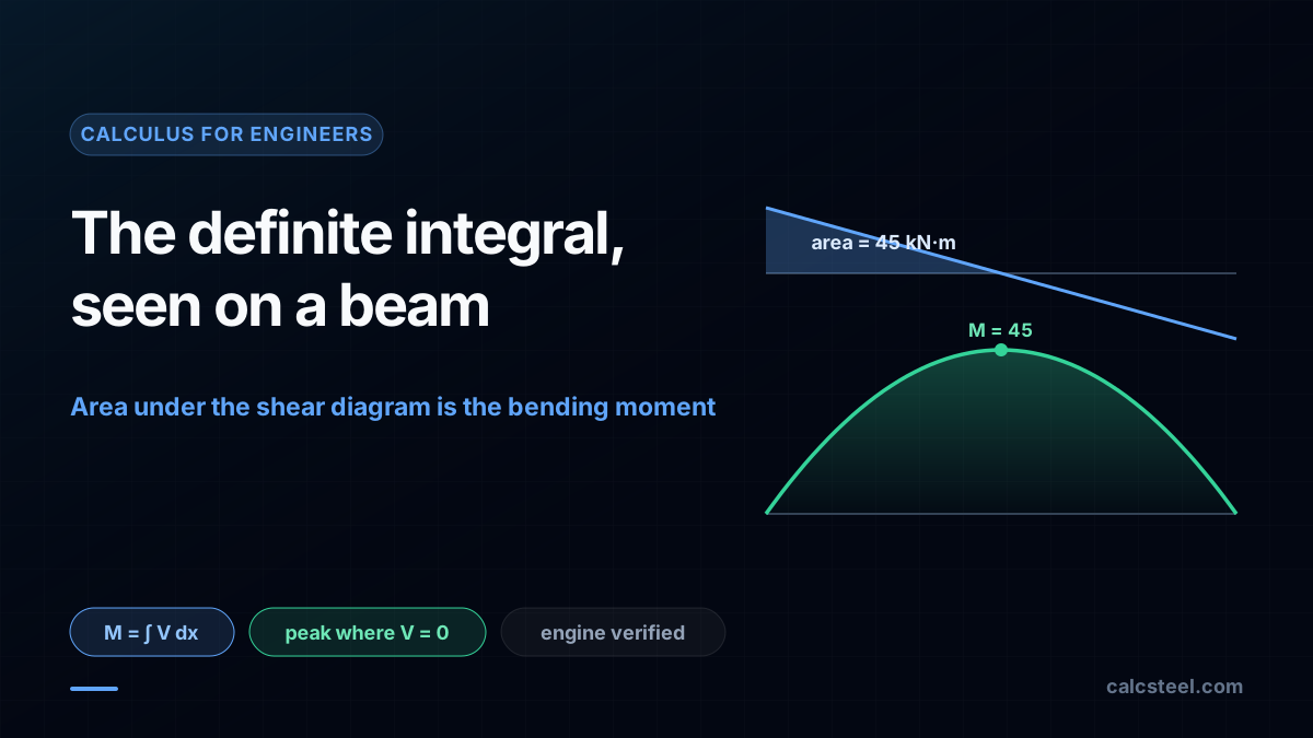
The definite integral you met in Calculus I is not an abstraction you leave behind in the exam hall. It is the exact tool that turns a shear diagram into a bending moment diagram: the bending moment at any section of a beam is the signed area under the shear force up to that section. This guide connects the Fundamental Theorem of Calculus to the diagrams every structural engineer draws, with three worked beams computed on the real CalcSteel engine and a live calculator you can drive yourself.
Key takeaways
- The bending moment is a definite integral of the shear force: M(x) = M(0) + the area under the shear diagram from 0 to x. Add up the area, and you have the moment, no separate formula required.
- This is the Fundamental Theorem of Calculus on a beam. Because dM/dx = V, integrating the shear recovers the moment, exactly the inverse of taking the slope.
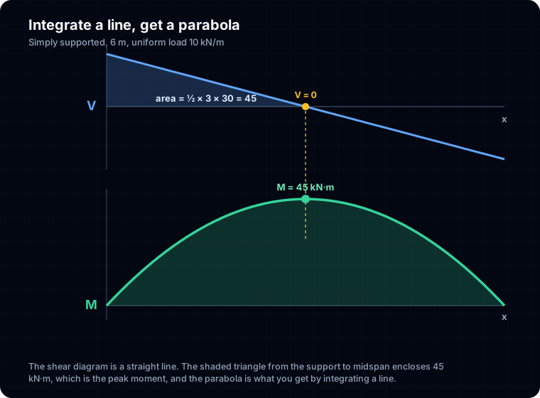
- Area has a sign. On the 6 m uniformly loaded beam the shear triangle from the support to midspan encloses 45 kN·m, and that IS the peak moment 45 kN·m. Past midspan the shear goes negative, its area subtracts, and the moment falls back to zero at the far support.
- The moment peaks where the shear crosses zero, because that is where the running area stops growing and starts shrinking. It is the same reason a function peaks where its derivative is zero.
- The shape of the shear diagram sets the shape of the moment: integrate a constant and you get a straight ramp, integrate a straight line and you get a parabola, integrate zero and the moment stays flat. Every worked number here was produced by the CalcSteel finite-element engine and the area check reproduced it to the last decimal.
The integral you were taught, hiding in a beam
Every engineering student integrates a hundred functions before graduating and then, somewhere around the first structures course, quietly wonders where any of it went. The answer is that it never left. The definite integral from Calculus I, the one you learned as the area under a curve, is the exact operation that turns a shear force diagram into a bending moment diagram. It is not an analogy. The bending moment at a section is a definite integral of the shear force, and this article is about seeing that directly.
Here is the whole idea in one sentence, and the rest of the guide is just this sentence made concrete: the bending moment at any point along a beam equals the signed area under the shear diagram from the left support up to that point. Draw the shear diagram, shade the area beneath it, read off the number, and you have the moment. No new formula, no table to memorise, just the integral you already know.
This is the companion to our guide on the derivative as a rate of change, which showed why dM/dx = V, the slope of the moment diagram is the height of the shear diagram. That was the derivative direction. This is the integral direction, the exact inverse, and the two together are the Fundamental Theorem of Calculus written on a steel beam. Every number below was computed by the CalcSteel engine, and the area under the shear was integrated numerically and matched the engine moment to the last decimal.
The definite integral, in one refresher
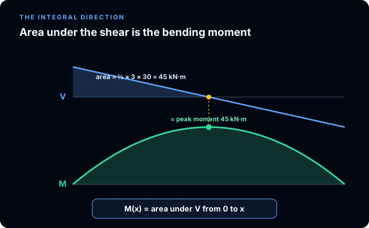
Strip it back to the calculus. The definite integral of a function f between a and b, written as the integral from a to b of f(x) dx, is the signed area between the curve and the horizontal axis. Signed matters: area above the axis counts as positive, area below counts as negative, and the integral is the net of the two. A curve that spends equal time above and below integrates to zero even though it clearly encloses area.
The Fundamental Theorem of Calculus is what makes this useful. It says that if F is an antiderivative of f, meaning dF/dx = f, then the definite integral from a to b of f equals F(b) − F(a). In words: integrating a rate of change over an interval gives you the total change in the quantity. Integrate a velocity and you get displacement. Integrate a flow rate and you get volume.
Now hold that sentence next to the one fact from the derivative guide: dM/dx = V. The shear force is the rate of change of the bending moment. So the moment is an antiderivative of the shear, and the Fundamental Theorem hands us the result immediately:
M(x₂) − M(x₁) = the integral from x₁ to x₂ of V dx = the area under the shear diagram between x₁ and x₂.
That is the entire theory. The change in bending moment between any two sections is the area under the shear diagram between them. If you know the moment at one point, usually zero at a simple support, you get the moment everywhere by accumulating area. The next three sections do exactly that on three real beams.
Load, shear, moment: a two step integration
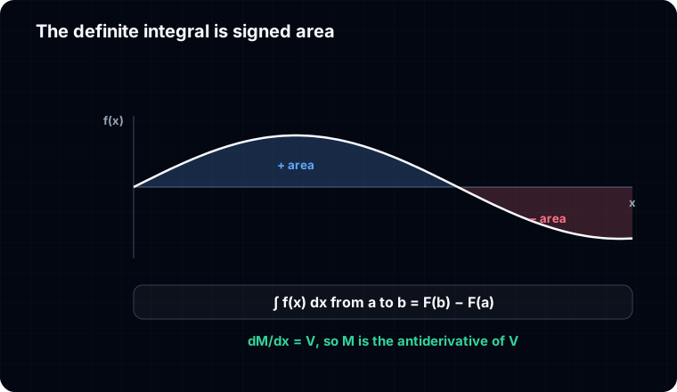
Before the worked beams, it helps to see the whole ladder, because the integral does not start at the shear. It starts at the load. Three quantities sit in a chain, each the integral of the one above it (with a sign):
distributed load w → shear V → moment M
Going down the ladder you integrate. The shear at a section is the (negative) area under the load diagram: V(x) = V(0) − the integral of w. The moment is the area under the shear: M(x) = M(0) + the integral of V. Going up the ladder you differentiate, which is the slope story of the derivative guide: dV/dx = −w and dM/dx = V. Same relations, read in opposite directions.
This is why the diagrams always come in a fixed pecking order of smoothness. A concentrated force is a spike in load; integrate it once and it becomes a jump in the shear; integrate again and it becomes a kink in the moment. A uniform load is a constant; integrate once for a sloping shear, again for a parabolic moment. Each trip through the integral sign makes the picture one degree smoother. Keep that in mind as the three beams below turn a constant into a ramp, a line into a parabola, and a zero into a flat top.
Worked beam 1: integrate a line, get a parabola
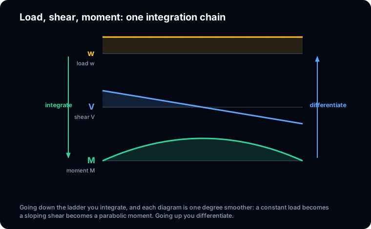
Start with the beam everyone draws first: a simply supported span of L = 6 m under a uniform load w = 10 kN/m. Each support carries half the total load, so the reactions are R = wL/2 = 30 kN. The shear starts at +30 kN over the left support and falls in a straight line as the load bleeds it away, reaching zero at midspan and −30 kN at the right support. The shear diagram is a straight line, sloping down at the rate of the load.
Now integrate it. The moment at any section is the area under that shear line from the left support. From 0 to midspan the shear diagram is a triangle: base 3 m, height 30 kN. Its area is
½ × base × height = ½ × 3 × 30 = 45 kN·m.
That area is the bending moment at midspan, and it matches the textbook result M_max = wL²/8 = 45 kN·m to the decimal. The engine agrees: solved as a real model, the midspan moment is 45 kN·m, and numerically integrating the engine's own shear diagram reproduces the whole moment curve with a maximum error of 0 kN·m. Because the integrand is a straight line and its integral is one degree higher, the moment diagram is a parabola. You did not derive the parabola, you integrated a line and the parabola fell out. Read the area at x = 1 m and you get 25 kN·m; at x = 2 m, 40 kN·m. Every point on the moment curve is just the running total of shear area to its left.
Why the moment peaks where the shear is zero
Look at what the area does as you sweep along the uniform beam. Over the left half the shear is positive, so every step to the right adds area and the moment climbs. At midspan the shear passes through zero. Just past it the shear is negative, so every further step subtracts area and the moment falls. The running total turns around at the exact point where the shear changes sign, and that is where the moment is largest.
This is not a coincidence you have to remember separately. It is the same rule from first year calculus that a function reaches a maximum where its derivative is zero. Here the moment is the accumulating integral and the shear is its derivative, so the moment peaks where V = 0. On the uniform beam that is dead centre, and the peak is the 45 kN·m we just computed as the triangle area.
One honest caution, because it is the classic exam trap: the moment peaks where the shear is zero only when there is no concentrated moment applied and no support in the way. Add an applied moment and the moment diagram jumps; on a continuous beam the largest magnitude can sit over an interior support where the shear is not zero at all. The safe habit is the one the shear and moment diagram guide insists on: find every point where the shear crosses zero, check the supports and any applied moments too, and take the largest magnitude of all of them.
Worked beam 2: integrate a constant, get a ramp
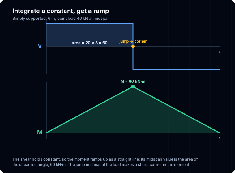
Swap the uniform load for a single point load. A simply supported beam of the same L = 6 m carries P = 40 kN at midspan. The reactions are R = P/2 = 20 kN each. Now the shear is a constant: there is no distributed load to erode it, so it holds at +20 kN all the way from the left support to the load, then jumps down to −20 kN and holds at that value to the right support. The shear diagram is a pair of horizontal rectangles.
Integrate a constant and you get a straight line, the ramp x scaled by the constant. So the moment climbs in a straight line from the support, and its value at midspan is simply the area of the first rectangle:
height × width = 20 × 3 = 60 kN·m.
That is the peak moment, and it matches PL/4 = 60 kN·m exactly. The engine returns 60 kN·m at midspan and the area integration of its shear diagram reproduces the triangular moment to 0 kN·m. Notice the contrast with beam 1. There the integrand was a line and the moment was a parabola; here the integrand is a constant and the moment is a straight ramp, one degree of smoothness lower because the shear itself is one degree less smooth. The jump in the shear at the load becomes the sharp peak in the moment: a corner, not a smooth turn, because the shear did not pass through zero gradually, it leapt across it.
Signed area, and why the moment comes back to zero
Both beams so far end the same way: the moment is zero at the right support, just as it was at the left. That is not luck, and the integral explains it cleanly. On a simply supported beam the moment starts at zero, because a pin cannot resist rotation, and it must return to zero at the other pin. For the running area to start at zero and finish at zero, the total signed area under the whole shear diagram has to be zero.
Check it on the point load beam. The positive rectangle on the left encloses +60 kN·m of area; the negative rectangle on the right encloses −60 kN·m. They cancel exactly, so the moment accumulated over the first half is spent back over the second half, landing at zero. On the uniform beam the positive triangle on the left and the negative triangle on the right are mirror images, same story. Whenever a beam returns to a simple support, the shear diagram it rode in on had to have equal positive and negative area.
This is also the fastest sanity check you can run on any diagram by eye. Glance at a shear diagram, estimate the positive and negative areas, and if they do not roughly balance on a simply supported span, something upstream is wrong, usually a reaction. The integral is not only how you build the moment diagram, it is how you catch a mistake in it.
Worked beam 3: integrate zero, get a flat top
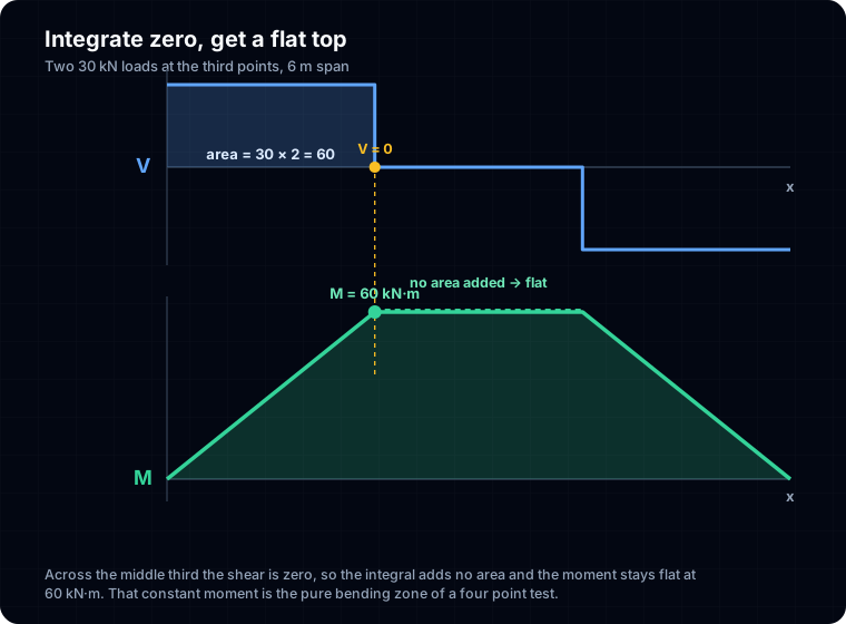
The third beam is the one that makes the integral impossible to unsee. Take the same L = 6 m span and apply two equal point loads of P = 30 kN at the third points, x = 2 m and x = 4 m. This is the classic four point bending setup, the arrangement a lab uses to test a beam in pure bending. Each reaction is 30 kN. The shear is +30 kN over the left third, then the first load knocks it down to zero across the whole middle third, then the second load drives it to −30 kN over the right third.
Integrate that. Over the left third the shear is a constant 30 kN, so the moment ramps up to the area of that rectangle, 30 × 2 = 60 kN·m, at x = 2 m. Then comes the beautiful part. Across the middle third the shear is zero, and the integral of zero is no area at all, so the moment does not change. It stays flat at 60 kN·m from x = 2 m to x = 4 m. The engine confirms the shear is identically zero there and the moment is a constant 60 kN·m plateau, integration error 0 kN·m.
A flat moment means constant curvature and constant stress: the middle third is in pure bending, no shear, which is exactly why the test is built this way. And you can read that entire physical fact straight off the calculus. Where the shear is zero, the moment is flat, because there is no area being added. Integrate a line and you get a parabola, integrate a constant and you get a ramp, integrate zero and nothing moves. Three beams, three integrands, three shapes, one theorem.
Try it: watch the area become the moment
Build the three beams yourself below. Set a span, drop a uniform load or a point load, and watch the shear and moment diagrams update together. Track one thing as you change the load: the moment at any section is always the area under the shear to its left. Move the load and the shear area redistributes, and the moment peak slides to wherever the shear now crosses zero. It is the fastest way to turn the theorem from a sentence into an instinct.
The same calculator that draws these diagrams is the front end of the full CalcSteel engine, so the numbers you see are the ones a real analysis would use. For the deeper walkthrough from a single beam all the way to a portal frame, the shear force and bending moment diagram guide takes it the rest of the way.
|V| max
30 kN
@ x = 6 m
M max (sagging)
45 kN·m
@ x = 3 m
M min (hogging)
-0 kN·m
@ x = 6 m
Reactions (kN)
R_A 30 · R_B 30
Simply supported beam — uniformly distributed load
Segment equations — x in m, from the left end
0 m ≤ x ≤ 6 m
V(x) = 30 − 10·x [kN]
M(x) = 30·x − 5·x² [kN·m]
Profiles that resist this moment
Md = 45 kN·m → required Wx = Md / (fy/γa1) = 45 kN·m / (250/1.1) = 198 cm³
Bending screen (Wx ≥ Md/(fy/γa1), NBR 8800 γa1 = 1.10 — AISC 360 φb = 0.90 is nearly identical); plastic Zx is valid for compact sections only. δ is the elastic deflection of THIS loading with E = 200 GPa and the section's Ix (loads taken at service value). LTB, shear, compactness and code deflection limits are verified on the profile page and in the 3D editor. "Open in 3D editor" recreates THIS beam — span, supports and every load — with the profile already assigned.
Integrate again: from Calculus II to deflection
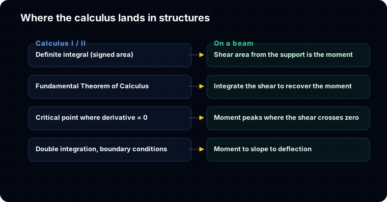
The integral does not stop at the moment. Take one more trip through the antiderivative and you reach the shape the beam actually bends into. The curvature of the beam is the moment divided by its bending stiffness, M/EI. Integrate the curvature once and you get the slope of the deflected beam; integrate the slope once more and you get the deflection itself. That is two more definite integrals stacked on top of the one this article is about, and it is exactly the double integration method taught in a first course on structures.
So the full chain, from the load a roof carries to the millimetres a beam sags, is four integrations deep: load to shear, shear to moment, moment to slope, slope to deflection. The constants of integration that appear at each step are fixed by the supports, the boundary conditions, which is where Calculus II earns its place in the curriculum. This is the honest answer to the student who asks what the integral was for: it is the spine of structural analysis, and the shear to moment step is simply the one where you can see the area with your own eyes.
Five ways the integral gets misread
The mistakes are consistent, and every one is a misreading of the integral rather than of the beam:
1. Reading the ordinate instead of the area. The moment at a section is not the height of the shear there, it is the accumulated area up to there. A large shear with little area behind it makes a small moment; a modest shear sustained over a long span makes a large one.
2. Forgetting the sign of the area. Past the point where the shear goes negative, its area subtracts. Students who add magnitudes get a moment that keeps climbing to the far support instead of coming back to zero.
3. Dropping the constant of integration. M(x) = M(0) + area only starts at zero if the moment is zero there. On a cantilever or over a continuous support the starting moment is not zero, and the area is added on top of it, not from scratch.
4. Expecting the peak at V = 0 no matter what. True for distributed loads, but an applied concentrated moment makes the diagram jump, and an interior support can hold the largest magnitude while the shear there is nonzero. Check the crossings, the supports and the applied moments, then take the biggest.
5. Treating a point load as if it had width. A concentrated force is a jump in the shear, an infinitely thin spike in load. It adds no area by itself; what it does is move the shear level, which changes the area accumulated on either side of it.
What the engine does under the hood
When CalcSteel draws a moment diagram it is doing the integral you just did by hand, only numerically and at every section at once. The finite element solver returns the shear and moment at the ends of each element, and the moment at any station is the running sum of the shear area from the support. For the three beams in this article we ran that check the other way around: we took the engine's shear diagram, integrated it by the trapezoidal rule, and compared the result to the engine's own moment diagram. The two agreed to 0 kN·m, which is to say exactly, on all three beams.
That is the whole point of the theorem for a working engineer. You do not need to trust the software as a black box, because the moment diagram it produces has to be the integral of the shear diagram it produces, and you can verify that by eye with the area of a triangle. The definite integral from Calculus I is not background knowledge here. It is the thing the software is computing, and the thing you should be able to check it against. For the slope side of the same coin, the derivative guide is the other half of the Fundamental Theorem, and together they are the calculus that every diagram in structural engineering rests on.
Sources
- 1.Stewart, J., Calculus: Early Transcendentals (the definite integral and the Fundamental Theorem of Calculus)
- 2.Hibbeler, R.C., Structural Analysis (relations between load, shear and moment; the area method)
- 3.Gere & Goodno, Mechanics of Materials (shear force and bending moment diagrams, four point bending)
- 4.Hughes, T.J.R., The Finite Element Method (element internal forces and diagram recovery)
Try CalcSteel for free
Model, analyze and design steel structures in your browser. No install, no signup.
Open the 3D editor