Strain Energy and Impact Loading: What a Dropped Load Does That a Static One Does Not
Strain energy is the energy a member stores as it deforms, and it is the key to impact loading. The same weight lowered gently and dropped a few centimetres produces very different stresses in the same steel beam. This guide derives the impact factor from energy balance, works a real IPE 200 example on the CalcSteel engine, and shows why a stiffer beam is not automatically a safer one under impact.
Key takeaways
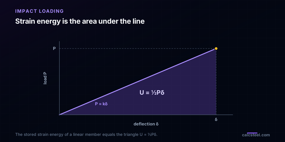
- Strain energy is the area under the load-deflection curve: U = ½Pδ for a linear elastic member, which behaves like a spring.
- A suddenly applied load, with zero drop height, produces exactly twice the static deflection and stress. The impact factor is n = 2.
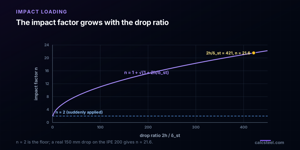
- For a load dropped from height h, the impact factor is n = 1 + √(1 + 2h/δ_st), where δ_st is the static deflection under that load.
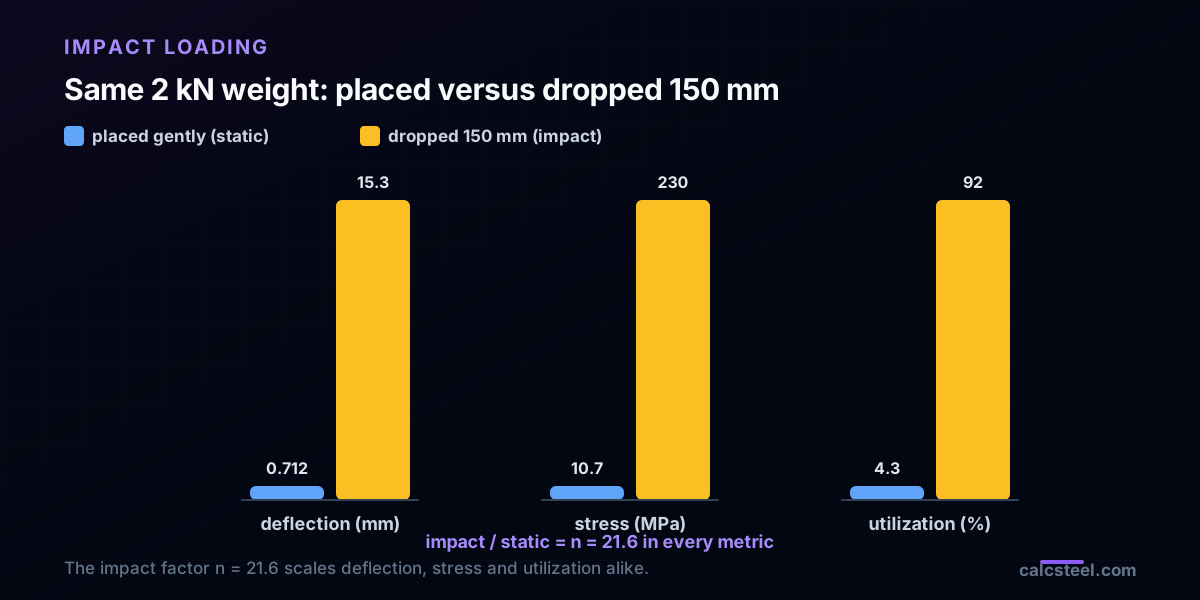
- In the worked example a 2 kN weight sits harmlessly on an IPE 200 (10.7 MPa, 4.3% utilization), but dropped from 150 mm it reaches 230 MPa (92%): the impact factor is 21.6.
- A stiffer or shorter beam deflects less, so its impact factor is larger. What lowers impact stress is the capacity to store strain energy, which favours more material, longer members, and no stress concentrations.
What is strain energy?
Strain energy is the energy stored inside a body as it deforms under load. In an elastic member it is fully recoverable: release the load and the member springs back, returning the energy it stored. That single idea is what links a routine static check to what happens when a load is dropped.
For a linear elastic member the load grows from zero to its final value P while the deflection grows from zero to δ. Because force and deflection rise together in proportion, the work done on the member, and therefore the strain energy stored in it, is the area of a triangle:
U = ½Pδ
A beam under load is just a stiff spring. Write P = kδ, where k is the member stiffness (for a simply supported beam with a central point load, k = 48EI/L³), and the same energy becomes U = ½kδ². Per unit volume of material the stored energy density is u = σ²/2E, the area under the stress-strain line. Everything that follows about impact comes from tracking this energy as a falling weight delivers it. It is the same accounting that powers the energy methods used to compute deflections.
Why a dropped load is not the same as a static one
A static load and a dropped load can carry the same weight, but they deliver their energy in completely different ways.
A static, gradually applied load rises from zero. At every instant the member only feels as much load as its current deflection can resist, so the external work is the triangle ½Pδ, and it equals the strain energy stored. Nothing is left over.
A dropped or suddenly applied load arrives at full value. The whole weight W is present from the first instant of contact and keeps doing work, force times distance, all the way down until the member finally stops it at maximum deflection. The member has to absorb every bit of that energy as strain energy. There is no gentle ramp to share the load with.
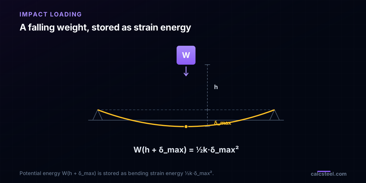
The tool for the rest of this article is conservation of energy. Neglecting damping, sound, heat and local crushing at the contact, and assuming the member stays elastic, the potential energy the weight loses as it falls equals the strain energy stored in the member at maximum deflection. That balance is all you need to find how hard the load really hits.
The suddenly applied load: a factor of two, for free
Start with the gentlest possible dynamic case: the weight is released while just touching the beam, with zero drop height. It is still not a static load, because it acts at full value from the first instant.
Set h = 0 in the energy balance. The weight descends only δ_max, so it releases W·δ_max, and that becomes strain energy ½k·δ_max²:
W·δ_max = ½k·δ_max²
The static deflection under the same weight is δ_st = W/k, so W = k·δ_st. Substitute and cancel one δ_max:
k·δ_st·δ_max = ½k·δ_max² → δ_max = 2δ_st
A suddenly applied load produces exactly twice the deflection, twice the bending moment, and twice the stress of the same load applied gradually. The impact factor is n = 2. This is the floor: however carefully you set a load down and let go, it hits twice as hard as it weighs. On the worked IPE 200 below, the 2 kN weight that deflects the beam 0.712 mm and stresses it to 10.7 MPa when placed gently reaches 1.42 mm and 21.4 MPa the instant it is released in contact.
The impact factor for a load dropped from a height
Now let the weight fall a height h before it touches the beam. At maximum deflection it has descended h + δ_max in total, so it has released potential energy W(h + δ_max). Set that equal to the strain energy stored:
W(h + δ_max) = ½k·δ_max²
Divide through by W and use W = k·δ_st:
h + δ_max = δ_max² / (2δ_st)
Solve the quadratic for δ_max and keep the physical, positive root:
δ_max = δ_st · [ 1 + √(1 + 2h/δ_st) ]
The bracket is the impact factor:
n = δ_max / δ_st = 1 + √(1 + 2h/δ_st)
Because the member is linear, every static result scales by the same n: δ_max = n·δ_st, M_max = n·M_st, and σ_max = n·σ_st. Two limits are worth remembering. At h = 0 the formula gives n = 2, the suddenly applied case. For a large drop, h much greater than δ_st, it tends to n ≈ √(2h/δ_st), so the stress grows only with the square root of the drop height. Doubling the height does not double the stress, and a small δ_st, that is, a stiff member, makes n large. Hold on to that last point.
Worked example: a 2 kN weight dropped on an IPE 200
Take a simply supported IPE 200, span L = 4.0 m, and a W = 2.0 kN weight (about 204 kg) at midspan, dropped from h = 150 mm. Steel yield f_y = 250 MPa. The CalcSteel section engine reports A = 28.5 cm², I_x = 1873 cm⁴, and section modulus S_x = 187.3 cm³.
Static, load placed gently
δ_st = W·L³ / (48·E·I_x) = 0.712 mm. The shipping FEM engine returns 0.712 mm at the midspan node, matching the closed form to three decimals. The moment is M_st = W·L/4 = 2.0 kN·m, so the bending stress is σ_st = M_st / S_x = 10.7 MPa. Against f_y = 250 MPa that is a utilization of 4.3%. Statically, this is a non-event.
The same weight, dropped 150 mm
n = 1 + √(1 + 2 × 150 / 0.712) = 21.6. Every static result multiplies by that factor:
- δ_max = 21.6 × 0.712 = 15.3 mm
- M_max = 21.6 × 2.0 = 43.1 kN·m
- σ_max = 21.6 × 10.7 = 230 MPa, a utilization of 92%
Energy check. The weight releases W(h + δ_max) = 2.0 × (0.150 + 0.0153) = 331 J, and the beam stores ½k·δ_max² = 331 J. They match, because that balance is exactly where the factor came from.
So the same 2 kN, dropped 150 mm, does to the beam what a 43 kN static load would. It goes from 4.3% utilization to 92% without changing weight by a gram. Drop it from about 180 mm instead of 150 and the outer fibre reaches f_y: the beam yields.
Try it: read your own static deflection, then apply the factor
The impact factor needs exactly one number from analysis: the static deflection δ_st under the weight applied as an ordinary load. Model your beam below, read δ_st and the static bending stress, then multiply by n = 1 + √(1 + 2h/δ_st) for the drop height you care about. For a load that is simply released in contact, use n = 2.
Max moment
45 kN·m
Max shear
30 kN
Max deflection
10.55 mm
= L/569
Bending stress σ
84.4 MPa
σ = M/Sx
Utilization
44.0%
NBR 8800 · δ ≤ L/250
Geometry & supports
Section
Ix 7999 cm⁴ · Sx 533 cm³ · 42.2 kg/m
Point loads (↓ positive)
None — add as many as you need.
Distributed loads (uniform or trapezoidal)
Model sketch
Diagrams — free PNG / SVG / CSV export, no watermark
Step-by-step — the calculation memory of YOUR beam
IPE 300 · L = 6 m · fy = 250 MPa
1. Reactions (equilibrium of the solved FEM model)
ΣFy = 0 · ΣM = 0
R_A = 30 kN · R_B = 30 kN
2. Peak shear (read from the SFD)
Vmax = |V(x)|max
Vmax = -30 kN @ x = 6 m
3. Peak moment (read from the BMD)
Mmax = |M(x)|max
Mmax = 45 kN·m @ x = 3 m
4. Peak deflection
EI = 15998 kN·m² (E = 200 GPa)
δmax = 10.55 mm @ x = 3 m = L/569
5. Elastic bending stress
σ = Mmax / Sx = 45.00 × 10³ / 533.3
σ = 84.4 MPa
6. Bending check — both codes, side by side
NBR 8800: σ ≤ fy/1.10 = 227.3 MPa · AISC 360: σ ≤ 0.90·fy = 225 MPa
NBR 37.1% PASS · AISC 37.5% PASS
7. Deflection check (serviceability — code-independent)
δ ≤ L/250 = 24 mm
10.55 mm / 24 mm = 44.0% PASS
Recomputed live from the current inputs by the direct-stiffness FEM engine — change any load and every step updates. Reproduce it by hand with the formulas in the sections below.
Lightest catalog profiles that pass (974 flexural candidates · NBR 8800)
| Profile | Std | Weight | Total steel | σ util | δ util | |
|---|---|---|---|---|---|---|
| W310x21 | AISC | 21 kg/m | 126 kg | 83% | 98% | |
| VS 300x23 | BR | 22.6 kg/m | 136 kg | 71% | 84% | |
| U 300x90x6.3 | BR | 23.1 kg/m | 139 kg | 82% | 98% | |
| U 300x100x6.3 | BR | 24.1 kg/m | 145 kg | 77% | 91% | |
| VS 250x25 | BR | 24.6 kg/m | 148 kg | 70% | 100% |
Elastic bending (σ = M/Sx vs fy/γa1, γa1 = 1.10 — NBR 8800) + deflection screening of the full flexural catalog. Lateral-torsional buckling, shear and local buckling are NOT checked here — run the full NBR 8800 / AISC 360 verification in the 3D editor.
The stiffness trap: stiffer is not safer under impact
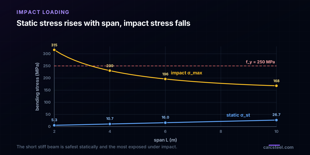
Static intuition says a shorter, stiffer beam is safer: it deflects less and its moment W·L/4 is smaller. Under impact that intuition inverts, and the reason is in the formula. The impact factor depends on δ_st, and a stiffer beam has a smaller δ_st, so a larger n.
Hold the same IPE 200, the same W = 2 kN and the same h = 150 mm, and change only the span:
| Span L | δ_st | σ_st (static) | n | σ_max (impact) |
|---|---|---|---|---|
| 2 m | 0.089 mm | 5.3 MPa | 59.1 | 315 MPa |
| 4 m | 0.712 mm | 10.7 MPa | 21.6 | 230 MPa |
| 6 m | 2.40 mm | 16.0 MPa | 12.2 | 196 MPa |
| 10 m | 11.1 mm | 26.7 MPa | 6.3 | 168 MPa |
As the span grows the static stress rises, from 5.3 to 26.7 MPa, but the impact stress falls, from 315 to 168 MPa. The short stiff beam is the safest statically and the most dangerous under impact. The long flexible beam is the reverse. For a large drop, σ_max ≈ σ_st·√(2h/δ_st), which works out proportional to 1/√L: the very length that hurts you statically helps you under impact, because a longer member soaks up the same energy at a lower stress. Note that the 2 m and 4 m rows predict stresses at or above f_y = 250 MPa, which the elastic formula cannot actually deliver. That is the subject of a later section.
Strain energy per unit volume: resilience and toughness
Why does more material or more length lower the impact stress? Because impact is about the energy a member can absorb, and that scales with volume.
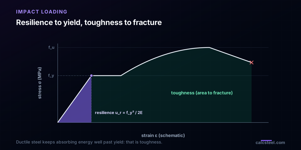
The strain energy density, the energy stored per unit volume at a stress σ, is u = σ²/2E. The most a material can store while staying elastic, right up to yield, is the modulus of resilience:
u_r = f_y² / 2E
For f_y = 250 MPa and E = 200 GPa that is 0.156 MJ/m³, about 156 kJ/m³. The elastic energy a whole member can store before first yield is u_r times the effectively stressed volume. In bending only the outer fibres reach f_y, so the usable fraction is smaller than in pure tension, but the message holds: a bigger, longer member has more volume to spread the energy through, so it reaches yield at a lower peak stress.
Toughness is the whole area under the stress-strain curve out to fracture, the energy per volume including plastic work. Mild steel is tough because it yields and keeps absorbing energy long after first yield. That is why a ductile steel survives impacts that would shatter a brittle material of the same strength: it trades a permanent set for not fracturing.
The trap inside the trap: stress concentrations under impact
If impact stress falls when energy is spread over more volume, then the worst thing you can do is force the energy into a small volume. A notch, a bolt hole, a re-entrant corner or an abrupt change of section does exactly that: it makes the member store most of its strain energy in a tiny region around the discontinuity.
Statically, a stress concentration factor K_t raises the local stress by a fixed multiple, and for ductile steel that is usually the end of it, because it yields locally and redistributes. Under impact the effect compounds. The small, highly stressed volume has almost no capacity to absorb energy, so the local stress climbs far faster than K_t alone would suggest. A classic result from mechanics of materials is that a stepped or grooved bar can fail under an impact that a uniform bar of the same minimum area shrugs off, because the uniform bar spreads the energy over its whole length while the grooved bar dumps it into the groove.
Practically: keep changes of section gradual, avoid sharp re-entrant corners, keep bolt holes and copes away from regions that see shock or dynamic load, and grind out nicks and notches on members exposed to impact. A detail that is invisible under static load can govern under a dropped one.
When the elastic impact factor stops being true
The formula n = 1 + √(1 + 2h/δ_st) rests on two assumptions: the member stays linear elastic, and no energy is lost to damping, sound, heat or local crushing at the point of contact. Both matter.
If the elastic prediction gives σ_max above f_y, as the 2 m span did at 315 MPa against f_y = 250, the member cannot actually reach that stress. Instead it yields, and the plastic deformation absorbs energy at roughly constant stress. The good news is that a ductile member can absorb far more energy after yield than before, so it may survive a single impact by taking a permanent set. The bad news is that it is now bent, its residual capacity is reduced, and a second impact finds a member that is already damaged. The elastic factor is no longer the answer once it predicts yield; it only tells you that the elastic reserve has been used up.
Real energy losses cut the other way and reduce the peak. A rubber pad, a bolted joint that slips, or the crushing of material at the contact all remove energy before it reaches the member as bending strain energy. This is why crane rails, machine mounts and impact barriers are deliberately detailed to dissipate energy rather than reflect it. The formula is the clean upper bound; good detailing is how you stay below it.
Where impact shows up in steel design
Codes rarely ask you to derive n from a drop height. Instead they fold impact into a load amplification factor for the cases where dynamic effects are routine, and they are conservative on purpose.
Cranes. AISC 360 Section A4.2 increases nominal crane loads for vertical impact: 25% for monorail cranes and for cab-operated or remotely operated bridge cranes, 10% for pendant-operated bridge cranes, and 0% for hand-geared cranes. The crane runway beam is sized on the amplified wheel load.
Machinery and moving loads. ASCE 7 adds impact allowances: elevator loads are increased 100%, light shaft- or motor-driven machinery 20%, reciprocating machinery or power-driven units 50%, and hangers supporting floors and balconies 33%.
Seismic design is the same idea at building scale. What keeps a frame standing in an earthquake is its capacity to absorb and dissipate energy, not raw strength, which is why ductile detailing and braced frames that yield in a controlled way are preferred over brittle ones.
Vehicle impact posts, crash barriers and dropped-object protection on industrial and offshore structures are all sized on energy absorbed, not on a static-equivalent load alone. The thread through all of them is the one this article started with: a moving mass carries energy, and the structure has to store it or dissipate it.
How CalcSteel helps you check impact
Once you have the static deflection and the static stress, the impact factor is arithmetic, and those two numbers are exactly what the CalcSteel engine computes for every member and every load combination.
The workflow is short. Model the member, apply the moving or dropped load as an ordinary static load, and read δ_st at the point of impact together with σ_st or the utilization from the results. Then either multiply the static demand by the code impact factor for your situation, a crane or machine allowance, or amplify by n = 1 + √(1 + 2h/δ_st) for a genuine drop, and re-check the amplified moment and stress against the section capacity.
Because the engine reports deflection and stress to the same precision as the closed form, the worked example above matched to three decimals, you can trust the δ_st that feeds the factor. For crane runways and machine supports, add the AISC or ASCE percentage as an extra load case. For a true dropped load, amplify by n and confirm the member stays below yield, because once the elastic prediction crosses f_y the simple factor no longer holds and you are into the plastic energy discussion above.
Sources
- 1.R. C. Hibbeler, Mechanics of Materials (Resistencia dos Materiais), Chapter 14 (Energy Methods)
- 2.AISC 360-22, Specification for Structural Steel Buildings, Section A4 (Structural Design Loads, including crane and impact loads)
- 3.ASCE/SEI 7, Minimum Design Loads and Associated Criteria for Buildings and Other Structures (impact loads for cranes, machinery and elevators)
- 4.Timoshenko & Gere, Mechanics of Materials
Try CalcSteel for free
Model, analyze and design steel structures in your browser. No install, no signup.
Open the 3D editor