Moment Distribution (Hardy Cross): The Method That Built the Twentieth Century, on a Portal Frame
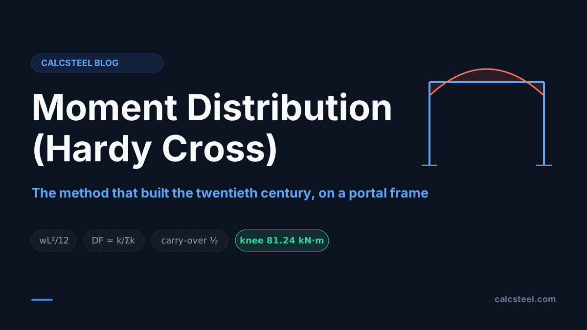
Learn moment distribution (Hardy Cross) end to end: fixed-end moments, distribution factors and carry-over, worked by hand on a real portal frame and verified to better than 0.1% on the CalcSteel FEM engine, with a free live calculator.
Key takeaways
- Moment distribution turns an indeterminate frame into arithmetic: lock every joint, compute the fixed-end moments, then release the joints one at a time and let the out-of-balance moment share out by stiffness.
- Three numbers run the whole method: the fixed-end moment (wL²/12 under a uniform load), the distribution factor (a member's share of the joint stiffness) and the carry-over factor (half of the balancing moment travels to the far fixed end).
- On our portal frame the beam fixed-end moment of 106.7 kN·m relaxes to a knee moment of 81.2 kN·m as the columns rotate: the hand table and the CalcSteel FEM engine agree to better than 0.1%.
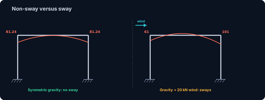
- A symmetric frame under symmetric load does not sway, so pure moment distribution is exact. Add wind and the frame leans, the leeward knee climbs to about 101 kN·m, and you need the sway correction or a solver.
- The knee moment is the start of design: W ≥ M / f_yd sets the section, the class decides plastic Z versus elastic W_el, and a frame member carries axial plus bending, not bending alone.
The method that built the twentieth century
For most of the twentieth century, every rigid concrete and steel frame you can name was solved without a computer. The engineers who designed them had a method, and for roughly thirty years it was the method: moment distribution, published by Hardy Cross in 1930. With nothing but a stiffness ratio, a fixed-end moment and a lot of patience, it made statically indeterminate frames solvable by pencil, and it stayed the most widely practised structural method until computers took over in the 1960s.
This guide teaches that method the whole distance, and it ends where the method earns its fame: a rigid portal frame, the two-column, one-beam skeleton under almost every warehouse and shed ever built. You will lock the joints, write the fixed-end moments, and then release the frame joint by joint and watch the moment redistribute until it balances, exactly the way Cross taught it. Every number here was produced by the CalcSteel finite-element engine and checked against the hand calculation to better than a tenth of a percent.
We wrote it for three readers. If you are a student meeting this in Análise Estrutural or Estruturas I, it is the worked example your course runs out of time to finish. If you are a practising or freelance engineer, it is the sanity check you can run in your head before you trust the software. And if you already know slope-deflection, this is its faster cousin: no simultaneous equations, just balance and carry over.
The CalcSteel portal frame calculator is free, runs in your browser with no login for the math, and solves the same frame this article works by hand. You can check every value below against it as you read.
Why a portal frame refuses to be solved by statics
Take a single-bay portal frame with rigid corners and fixed feet. Cut it free of the ground and count the unknown reactions: each fixed base carries a horizontal force, a vertical force and a moment, so six reaction components in all. Statics gives you only three equations in a plane, ΣFx = 0, ΣFy = 0 and ΣM = 0. Six unknowns, three equations: the frame is statically indeterminate to the third degree. Equilibrium alone cannot find the moments. There are infinitely many force systems that balance the loads, and only one of them also keeps the frame continuous at the rigid knees.
That missing information is stiffness. The real answer is the one where the members bend into a shape that fits together at every joint, and the stiffer a member is, the larger the share of moment it draws toward itself. Any method that solves the frame, whether it is slope-deflection, the finite element method, or the one in this article, is really just a way of enforcing that compatibility.
Before Hardy Cross, the practical route was slope-deflection: write a compatibility equation at every joint and solve the simultaneous set. For a two-span beam that is two equations. For a multi-storey frame it is dozens, by hand, with no matrix libraries to help. Cross's insight was to skip the simultaneous solve entirely and reach the same answer by successive approximation. If you want the formal test for how indeterminate a structure is before you start, our note on static determinacy and stability counts the degrees for you.
Where the method came from, and why it mattered
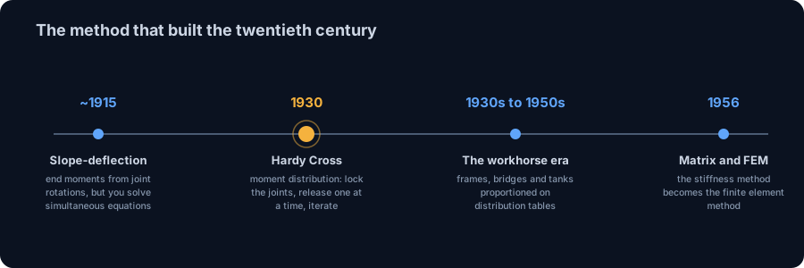
The story has a date and a place. In May 1930, Hardy Cross, then a professor at the University of Illinois, submitted a ten-page paper to the Proceedings of the American Society of Civil Engineers titled Analysis of Continuous Frames by Distributing Fixed-End Moments. It landed like a small revolution. When the formal discussion was published about two years later, thirty-eight commentators had added roughly 146 pages arguing over it. From the 1930s until computers became routine in design offices, moment distribution was the most widely practised method in structural analysis.
- Around 1915, slope-deflection. G. A. Maney and others formalise the slope-deflection method, which relates member end moments to joint rotations and sway. It is exact, but it needs you to solve simultaneous equations by hand.
- 1930, moment distribution. Hardy Cross replaces the simultaneous solve with iteration. Lock the joints, then release them one at a time and let the imbalance flow through the structure. The answer emerges by successive approximation, and the arithmetic is something a junior engineer can do at a desk.
- Through the 1930s to 1950s, the workhorse era. Frame buildings, bridges and water tanks across the world are proportioned on moment distribution tables. The method scales to multi-storey frames, non-prismatic members and sway, all by hand.
- 1956 onward, matrix and finite elements. Turner, Clough, Martin and Topp publish the stiffness formulation that becomes the finite element method. The computer solves the very simultaneous equations Cross had sidestepped, and does it for ten thousand members at once.
Moment distribution never became wrong, only outnumbered. It is still the fastest way to understand why a frame behaves as it does, and the surest hand-check on a solver. When the CalcSteel engine draws a frame's diagram in milliseconds, it is finishing the job Cross started, on the same physics.
The four ideas the whole method rests on
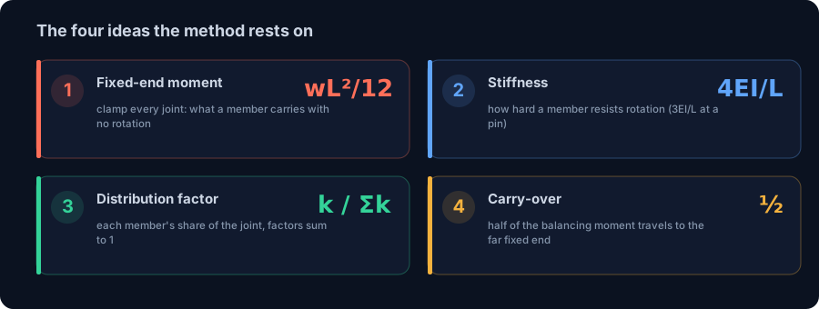
Moment distribution has a reputation for being fiddly, but it is built from just four ideas. Get these and the rest is bookkeeping.
1. Fixed-end moments (where you start)
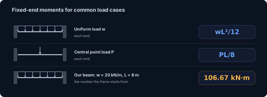
Imagine every joint clamped so it cannot rotate. Each loaded member then behaves like a beam built in at both ends, and the moments it exerts on those clamps are its fixed-end moments. They are tabulated for every common load. For a uniform load w over a span L the value is wL²/12 at each end. For a central point load P it is PL/8. These are the moments the structure would carry if no joint were allowed to turn, and they are the starting numbers of the whole table.
2. Stiffness (who resists rotation)
When you release a joint, the members meeting there share the job of resisting its rotation in proportion to their rotational stiffness, k = 4EI/L for a member whose far end is fixed. A short, deep member is stiff and holds on hard; a long, slender one is flexible and gives way. If the far end is a pin, the stiffness drops to 3EI/L, a correction that matters at every simple support.
3. Distribution factor (the share each member takes)
At a joint, each member's distribution factor is its stiffness divided by the total stiffness meeting there: DF = k / Σk. The factors at a joint always sum to 1.0, because the out-of-balance moment has to go somewhere. A stiff column at a knee takes the lion's share; a flexible rafter takes what is left.
4. Carry-over factor (the moment travels)
Balancing a joint bends each member, and that bending sends a moment to the member's far end too. For a prismatic member with a fixed far end, exactly half of the balancing moment carries over, so the carry-over factor is 1/2. This is the step that couples the joints together and the reason the method iterates: balancing joint B disturbs joint C, so you go back and balance C, which disturbs B, and so on until the disturbances fade to nothing.
Worked example 1: the fixed-end moment (the building block)
Start with the single number the whole portal frame is built on. Clamp a beam at both ends so neither can rotate, span L = 8 m, and load it with a uniform w = 20 kN/m. What moment does it push into each clamp?
The tabulated answer is M = wL²/12 = 20 × 8² / 12 = 106.67 kN·m of hogging at each end, with the top fibre in tension over the built-in supports. The mid-span sagging moment is half that in the other sense, wL²/24 = 53.33 kN·m. Those two numbers are the fixed-end condition: what the beam carries when no joint is allowed to turn.
We built this exact beam in the CalcSteel FEM engine as a control. It returned −106.667 kN·m at each end and +53.333 kN·m at mid-span, matching the closed form to three decimals. That agreement is not decoration. It is the proof that the engine reproduces the case you can check by hand, so you can trust it on the frame you cannot. Hold on to the 106.67 kN·m: it is the number that walks into the portal-frame table, and watch how much smaller it gets once the joints are free to rotate.
If you want the same idea for a cantilever or a propped beam, the tabulated fixed-end moments live alongside the closed forms in our shear and bending moment guide.
Worked example 2: a two-span beam, one joint to balance
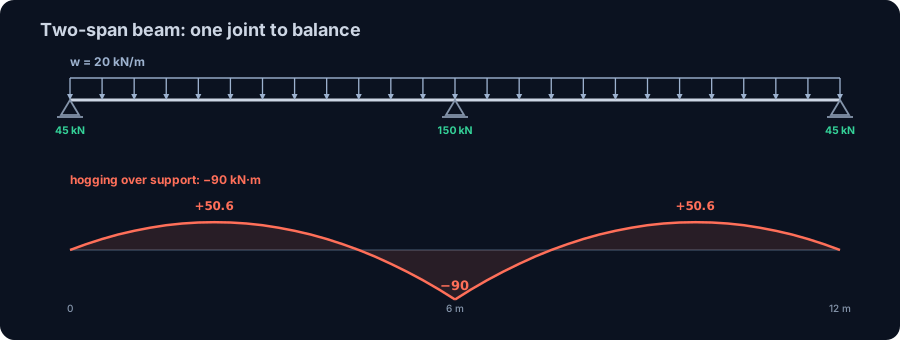
Before the frame, warm up on the case with a single free joint: a two-span continuous beam, two equal spans of L = 6 m, uniform load w = 20 kN/m, simple supports at the two ends and one in the middle. The interior support is the only joint that can rotate, so there is one balance to do.
Fixed-end moments
Clamp the interior support. Each span is now a fixed-end beam, so it delivers wL²/12 = 20 × 6² / 12 = 60 kN·m to that joint. The left span pushes it one way, the right span the other. Because the two exterior supports are pins, first release them: a pinned end can carry no moment, so its fixed-end moment is relaxed and half of it carries back to the interior joint, lifting each span's contribution to wL²/8 = 90 kN·m.
Balance the joint
With equal spans and equal load the two contributions are equal and opposite, so the interior joint is already balanced: the distribution factors (0.5 and 0.5) share out an imbalance of zero. The hogging moment over the middle support settles at 90 kN·m, the top fibre in tension, which is exactly the textbook −wL²/8 for this symmetric case.
What the engine returns
The CalcSteel engine gives −90.0 kN·m over the interior support, end reactions of 45 kN each, an interior reaction of 150 kN, and a sagging peak of 50.6 kN·m at 2.25 m into each span. The middle support carries far more than its share, 150 kN against 45 kN at the ends, because it is stiff and draws load toward itself. Load only one span instead of both, the classic pattern-loading check, and the joint no longer balances for free: the imbalance splits 0.5 / 0.5 and the support moment drops to wL²/16. That is moment distribution doing real work, and it is one line of a table.
The moment distribution recipe, in five steps
Every problem in this article, and every frame Hardy Cross ever solved, runs the same five steps. Once the numbers are in a table it is pure arithmetic.
- Lock the joints and write the fixed-end moments. Treat every member as built in at both ends, look up its fixed-end moment for the applied load, and enter both ends in the table with their signs.
- Compute the distribution factors at each free joint. Find each member's stiffness (4EI/L, or 3EI/L if its far end is a pin), and divide by the total stiffness at the joint. Check that the factors at each joint sum to 1.0.
- Balance a joint. Add up the moments at a free joint. The sum is the out-of-balance moment. Distribute its negative across the members in proportion to their distribution factors, so the joint now sums to zero.
- Carry over. Send half of each balancing moment to the far end of that member. This is what disturbs the neighbouring joints and sets up the next round.
- Iterate to convergence. Move to the next joint, balance, carry over, and keep cycling. Each pass is smaller than the last. Stop when the carry-overs are negligible, then sum each column: those totals are the final end moments.
That is the entire method. The only judgement calls are the stiffness correction at a pin (step 2) and, for frames that lean, a sway correction we get to shortly. Everything else is add a column, distribute, pass it on.
Draw your own: the live portal frame calculator
The fastest way to make the method stick is to change the frame and watch the moments move. Here is the CalcSteel portal frame calculator, live on this page. Set the span, the column height, the base fixity and the loads, and it solves the frame and draws the bending moment diagram instantly.
Try the frame from the next section first: an 8 m span, 5 m columns, fixed bases and a 20 kN/m gravity load, and confirm the knee moment near 81 kN·m for yourself. Then stiffen the columns or lengthen the beam and watch the knee moment climb or fall as the distribution factors shift. Add a horizontal load and the frame leans, the two knees stop being equal, and you can see the sway effect the hand method has to correct for.
It is the real solver, not a preview: unlimited runs, free, no login required for the math. If it opens in its own tab, here is the direct link to the portal frame calculator. For a single member with reactions, shear and moment together, the free beam calculator is the companion tool.
Diagrams plotted on the deformed-free frame geometry. N, V, M recovered from the element end-forces of the direct-stiffness solve (12 elements / member). Moment drawn offset to each member's centreline.
First-order STRENGTH screening at the governing section of the NBR 8800 (BR) ULS envelope (governing CB2): N,d = 73.9 kN, M,d = 109 kN·m. Member buckling and lateral-torsional buckling are NOT included — see the stability flags below and run the full verification in the 3D editor. Click a card to make that resistance code govern the ranking.
ULS load combinations — NBR 8800 (BR)
G + W superposed · 3 combinations| Combination | Factors | Utilization |
|---|---|---|
| CB1 | 1.4 G | 69% |
| CB2governs | 1.4 G + 1.4 W | 76% |
| CB3 | 1 G + 1.4 W | 57% |
Combinations generated by the CalcSteel combinations engine (the same v4 engine the 3D editor uses, 6 codes). Gravity is treated as a single permanent action G; the wind action W is the eaves load. Each combination's γ factors are applied by superposition to the isolated gravity and wind solves, then every section is screened — the worst point of the worst combination governs.
Stability screening (buckling caveats)
not in the strength checkScreening indicators only — assumed sway effective length (K = 1.5) and the full member length as the unbraced length (no intermediate purlin/girt restraint). The strength check above deliberately excludes these; the real member verification (effective lengths from the alignment chart / notional loads, χ and Cb reduction factors, purlin bracing) runs in the 3D editor.
Lightest sections that pass (NBR)
screened 974 profiles| Profile | Mass | Frame steel | Utilization | |
|---|---|---|---|---|
| VS 400x32 | 31.9 kg/m | 723 kg | 82% | |
| VS 350x33 | 33.2 kg/m | 752 kg | 86% | |
| VS 400x34 | 34.4 kg/m | 779 kg | 75% | |
| VS 350x35 | 35.1 kg/m | 795 kg | 80% | |
| VS 400x35 | 35.1 kg/m | 795 kg | 73% |
The climax: a portal frame solved by hand
Now the frame the method was built for. A single-bay portal: span L = 8 m, columns h = 5 m, rigid knees, fixed bases, prismatic members of constant EI, carrying a uniform gravity load w = 20 kN/m on the beam. It is symmetric, and the load is symmetric, so the frame does not sway: the two knees rotate by equal and opposite amounts and the whole thing stays put horizontally. That is exactly the case pure moment distribution solves exactly.
Set up the joints
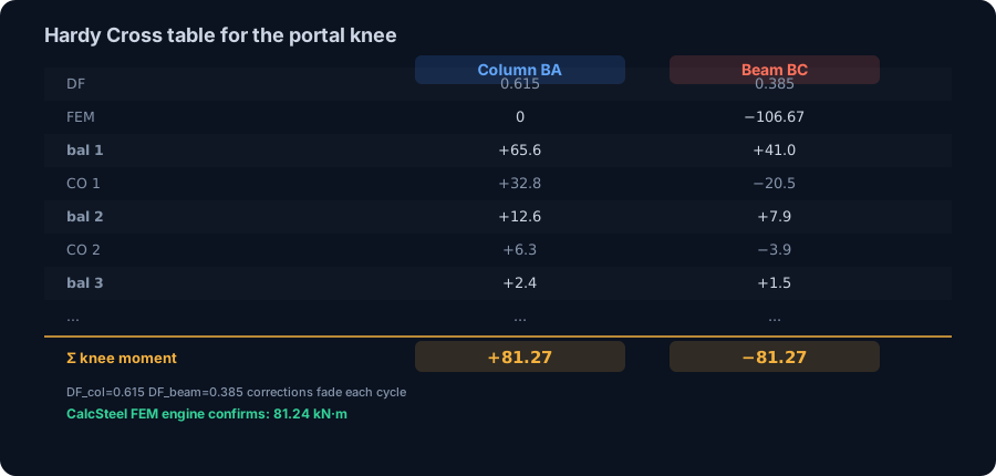
Only the two knees, B and C, can rotate. At knee B two members meet: the column (stiffness 4EI/h = 4EI/5) and the beam (stiffness 4EI/L = 4EI/8). Their distribution factors are
DFcolumn = (4EI/5) / (4EI/5 + 4EI/8) = 0.615 and DFbeam = 0.385.
The beam's fixed-end moment is the 106.67 kN·m from example 1. The columns carry no span load, so their fixed-end moments are zero. Joint C is the mirror image of B.
Balance and carry over
Release joint B. It is out of balance by the beam's −106.67 kN·m, so distribute +106.67 across the two members: the column takes 0.615 × 106.67 = +65.6, the beam takes 0.385 × 106.67 = +41.0. Carry over half of each to the far end: 32.8 down the column to the base, and 20.5 along the beam to knee C. But C is doing the same thing in mirror, and its carry-over lands back on B. So you balance B again (now out by −20.5), carry over again, and the correction shrinks each cycle: 12.6, then 2.4, then 0.5, then 0.1. After four or five cycles the columns of the table stop moving.
The result
Sum the table and the knee moment converges to 81.27 kN·m by hand. We built the identical frame in the CalcSteel FEM engine and it returned:
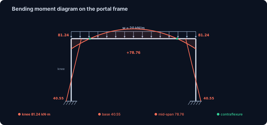
- Knee (eave) moment ≈ 81.24 kN·m, hogging, where column meets beam. The hand table and the engine agree to better than 0.1%.
- Column base moment ≈ 40.55 kN·m, which is the carry-over, half of the knee, exactly as the method predicts.
- Beam mid-span moment ≈ 78.76 kN·m of sagging.
- Base reactions: vertical 80 kN at each foot (the full wL/2 gravity share) and a horizontal thrust of about 24.4 kN pushing inward, the outward spread of the frame that the fixed feet hold back.
The redistribution story
Here is the payoff. The beam started with a fixed-end moment of 106.67 kN·m. As the joints were released and the columns rotated, that moment relaxed to 81.24 kN·m at the knee: about a quarter of it flowed out of the beam ends and down into the columns and bases. The frame shares the work around every joint instead of trapping it at the ends. That sharing is why rigid frames are efficient, and it is precisely what the distribution factors compute.
Reading the result: knee, base, mid-span and thrust
The table gives you end moments; the design lives in reading them. Four numbers matter on this frame, and each says something physical.
- The knee moment, 81.24 kN·m. This is the largest moment in the frame and the one that sizes the members at the eave. It is hogging, so the outer fibre of the corner is in tension: the flange on the outside of the knee, and the connection there, has to carry it.
- The base moment, 40.55 kN·m. Exactly half the knee, because a fixed far end receives half by carry-over. It is what makes the base a moment connection and sizes the holding-down bolts and the base plate. Pin the feet instead and this moment vanishes, but the knee moment rises to take up the slack.
- The mid-span moment, 78.76 kN·m. The sagging peak in the rafter. Note that on a simply supported 8 m beam under the same load it would be wL²/8 = 160 kN·m. Rigid frame action nearly halves it, because the knees now carry hogging that a simple beam cannot.
- The horizontal thrust, 24.4 kN. The frame wants to spread under gravity, and the fixed feet push back. That inward thrust is real force in the foundations, and forgetting it is a classic footing error.
Between the knee and mid-span the beam moment passes through zero: a point of contraflexure, where the tension face flips from the top of the knee to the bottom of the span. On our beam it sits about 1.2 m in from each knee. The columns have one too, roughly 1.7 m up from each base. These points mark where the braced flange changes and where you could splice a member with little moment to transfer, the same reading that governs a bending moment diagram on any member.
When the frame leans: sway and why software takes over
Everything so far worked because the frame did not move sideways. Symmetry bought us that. Now push the same portal with a 20 kN horizontal wind load at the eave and the symmetry is gone: the frame sways, the whole beam translates sideways, and every joint picks up an extra moment from that translation. Pure balance-and-carry-over no longer converges to the answer, because the sidesway itself contributes moments the fixed-end values never accounted for.
The hand cure is a two-stage moment distribution. First solve the non-sway frame by holding the beam against translation with an imaginary prop, and record the prop force. Then release the prop: apply an arbitrary sway, distribute the moments it causes, and scale that second solution so its prop force exactly cancels the first. Add the two and you have the real frame. It works, it is exact, and it roughly doubles the arithmetic, which is precisely where a busy office reaches for a solver.
Run our windward-plus-gravity case through the CalcSteel engine and the lean is obvious in the numbers:
- Leeward knee ≈ 101 kN·m against a windward knee ≈ 61 kN·m. Under gravity alone both were 81.24; the wind lifts one and relieves the other.
- Base moments split too, about 71 kN·m on the leeward foot against 10 kN·m on the windward one.
- The horizontal reactions sum to −20 kN, balancing the wind push exactly, while the vertical reactions still sum to the 160 kN of gravity.
This is the honest boundary of the hand method. Moment distribution can absolutely solve a sway frame, and generations of engineers did, but a multi-storey, multi-bay frame with several load combinations is where the tables become a full day's work and a solver becomes a click. The same physics, run by the wind combinations and the finite element method, is what a tool like the portal frame calculator does for you.
From moment to member: sizing the frame
A moment distribution table is not the destination. Its output, the knee moment, is the demand you size the steel against. The governing inequality is the same one that closes every flexural design: the section must supply more capacity than the demand.
W ≥ M / fyd
Here M is the design moment off the table, for this frame the 81.24 kN·m knee, fyd is the design yield stress (the characteristic yield divided by the material factor, γa1 in NBR 8800 or folded into φ in AISC 360), and W is the section modulus you look up in a profile table. Turn it around and the member capacity is MRd = W · fyd, and the design is valid when MRd ≥ MSd.
Which modulus you use depends on the section class. A compact section reaches its full plastic hinge, so you design on the plastic modulus Z (Wpl in NBR and Eurocode) and the plastic moment Mpl = Z · fyd. A non-compact or slender section buckles locally before it yields fully, so you are held to the elastic modulus Wel. The ratio Z / Wel, roughly 1.12 to 1.18 for a rolled I-section about its strong axis, is capacity you either use or leave on the table.
One warning specific to frames. The knee member is a column and a rafter at once: it carries axial force together with bending, not bending alone. So the real check at the eave is a combined axial and bending interaction, and the column also has to pass buckling under that axial load. In CalcSteel this is automatic: the same FEM run that produces the moments classifies every section, applies your code, and colours each member by its utilization, MSd / MRd, so you see at a glance which members drive the frame.
Common mistakes and FAQ
The method is only arithmetic, but a handful of slips account for most wrong answers. Run this checklist before you trust a table.
- Using 4EI/L at a pinned end. A member whose far end is a simple support has a stiffness of 3EI/L, not 4EI/L. Use the wrong one and every distribution factor at that joint is off. Better still, release the pin first and carry its moment back once.
- Sign errors in the fixed-end moments. The two ends of a loaded member push in opposite senses. Pick a sign convention, clockwise-positive is common, and hold it from the first entry to the last, or the balancing will fight itself.
- Stopping the iteration too early. The carry-overs shrink but do not hit zero. Stop while they are still a few percent of the total and your end moments are still visibly drifting. Carry on until a full cycle changes nothing at your precision.
- Forgetting the carry-over. Balancing a joint and not sending half to the far end decouples the structure and gives you a set of independent beams, not a frame. The carry-over is the frame.
- Ignoring sway. A frame that is not symmetric in both geometry and load will lean, and a non-sway distribution alone is wrong for it. Either add the sway correction or use a solver that includes it.
- Treating a rigid knee as a pin. Model the corner as a hinge and you delete the 81 kN·m knee moment, badly under-read the columns and completely misread how the frame carries load.
Is moment distribution exact or approximate?
The method itself is exact: carried to full convergence it gives the same answer as slope-deflection or the finite element method, because it enforces the same equilibrium and compatibility. What is approximate is where you stop. Each cycle is a closer approximation, and you truncate when the remaining carry-overs are below the precision you care about. For our frame, five cycles reach the engine value to better than 0.1%.
How is it different from slope-deflection?
They solve the same problem and reach the same answer. Slope-deflection writes a compatibility equation at every joint and solves the simultaneous set, so it is compact but needs linear algebra by hand. Moment distribution never forms those equations: it reaches the solution by iteration, one joint at a time, which is why a person can do a large frame with only a table. See our slope-deflection worked example for the other route on a similar structure.
Why did the beam moment drop from 106.67 to 81.24 kN·m?
Because the knees were free to rotate. The 106.67 kN·m was the fixed-end value, what the beam carries if the joints cannot turn. Releasing them let the columns take a share of the moment through their stiffness, so the beam end relaxed. The moment did not disappear: it moved into the columns and down to the bases. That redistribution is the whole point of a rigid frame.
Can I still solve a frame by hand today?
Yes, and it is worth doing at least once. A single-bay non-sway portal is a fifteen-minute table, and it builds the intuition no solver can hand you: which member is stiff, where the moment wants to flow, why a change to the columns moves the knee. Then let the software carry the volume. That combination, hand-sense plus machine-speed, is exactly how indeterminate structures are handled in practice.
Key takeaways
You have taken a frame that statics cannot touch and solved it with nothing but a stiffness ratio and patience, the same way the twentieth century did. Here is what to carry away.
- Lock, release, converge. Clamp every joint for the fixed-end moments, then release the joints one at a time. Balance the out-of-balance moment by distribution factor, carry half to the far end, and iterate until the corrections fade.
- Three numbers run it. The fixed-end moment (wL²/12 under a uniform load), the distribution factor (k / Σk, using 3EI/L at a pin), and the carry-over factor (1/2). Everything else is a table.
- Frames redistribute. Our beam's 106.67 kN·m fixed-end moment relaxed to an 81.24 kN·m knee as the columns took their share, and mid-span nearly halved against a simple beam. That sharing is what makes rigid frames efficient.
- Symmetry is a gift, sway is the catch. A symmetric frame under symmetric load does not lean, and pure distribution is exact. Add wind and the leeward knee jumps to about 101 kN·m; then you need the sway correction, or a solver.
- The moment is the start of design. The knee moment sets the required section modulus, the class decides plastic Z versus elastic W_el, and a frame member is checked for combined axial and bending, not bending alone.
Now do one by hand, then check it in seconds. Punch your own span, height, base fixity and loads into the free portal frame calculator and watch the knee moment move as you change the frame. When the frame grows to a real building, CalcSteel runs the same FEM engine on the whole structure in your browser, on a genuinely free plan, with every diagram, section class and code check included. Students get everything unlocked through CalcSteel Education, free. Hardy Cross would have loved how fast the table runs now.
Sources
Try CalcSteel for free
Model, analyze and design steel structures in your browser. No install, no signup.
Open the 3D editor