Buckling Restrained Braced Frames: the Steel Core Criterion Behind the Code
A buckling restrained braced frame puts the fuse inside the diagonal itself: a steel core that yields in tension and compression because a casing stops it from buckling. Here is the criterion behind the code, with a worked check on a real 25 × 110 mm core.
Key takeaways
- A BRB carries axial force in a slender steel core wrapped in a casing that restrains buckling, so the core yields the same way in tension and in compression, a ductile fuse with fat, symmetric hysteresis.
- The criterion is that there is no buckling penalty: the code lets you use the core yield Pysc = Fysc Asc directly, with no Fcr and no KL/r, in exchange for two conditions.
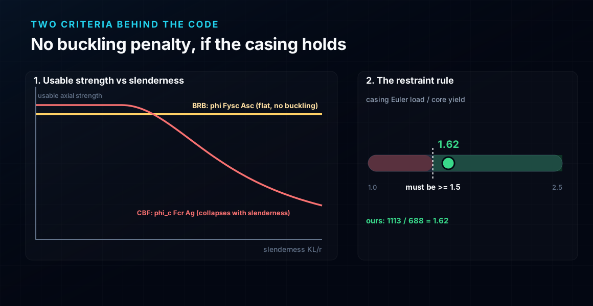
- Condition one is the restraint rule, the casing Euler load must beat the core yield with margin, Pe / Pysc ≥ 1.5; our SHS 180 × 8 casing gives 1113 / 688 = 1.62.
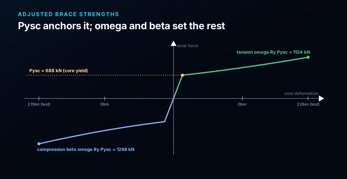
- Condition two is capacity design for the adjusted brace strengths, tension ωRyPysc = 1134 kN and compression βωRyPysc = 1248 kN, about 2.16 times the design demand.
- Worked 25 × 110 mm core: Pu = 579 kN, φPysc = 619 kN (94 %), core strain 1.31 % at the design drift and 2.63 % at the 2Δbm test amplitude, ductility μ = 9.6.
What a buckling restrained braced frame really is
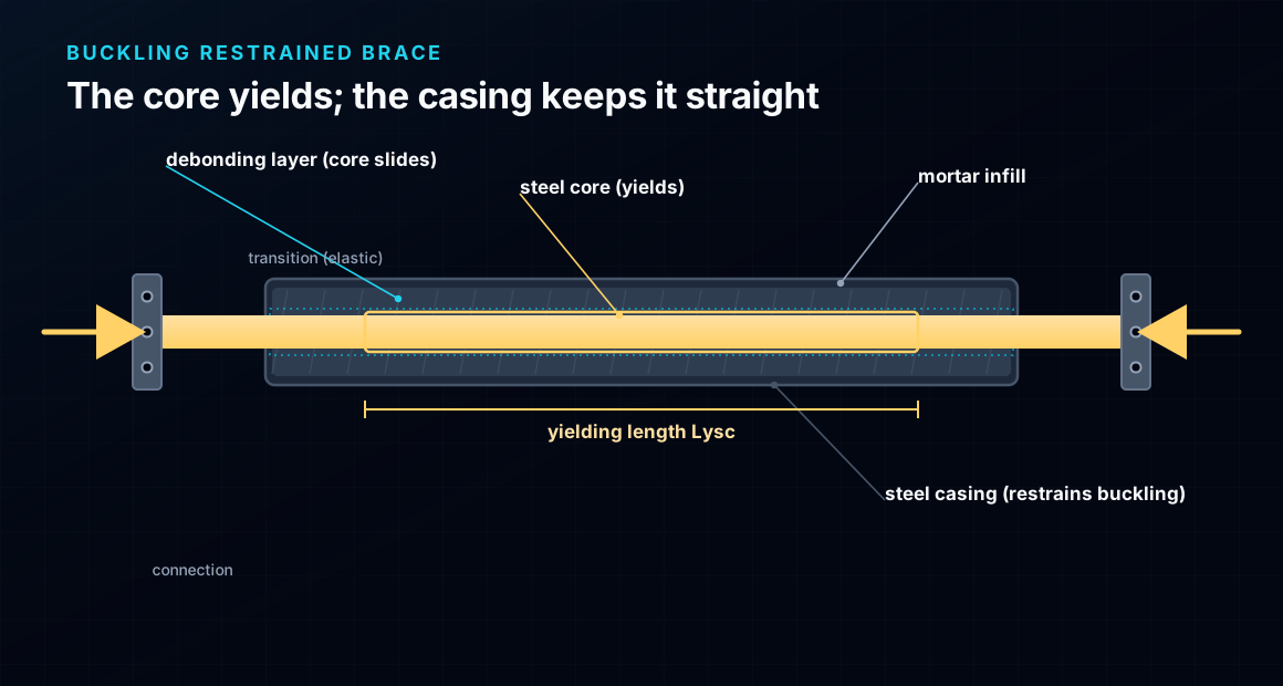
A buckling restrained braced frame (BRBF) looks like an ordinary braced bay with one diagonal doing something unusual. The steel that carries the axial force, the core, is a slender plate, far too slender to work in compression on its own. It does not have to. The core is wrapped in a stiff casing, a steel tube filled with mortar, with a thin sliding layer between them so the core can shorten and lengthen freely while the casing holds it straight. The core yields; the casing keeps it from buckling.
That one change rewrites the seismic behaviour. Because the core cannot buckle, it yields in compression at essentially the same force it yields in tension, cycle after cycle, absorbing energy like a ductile fuse while the beams, the columns, the gussets and the casing stay elastic. You get the stiffness of a braced frame without the pinched, one-sided degradation of a conventional diagonal.
Here is the part most references bury: the whole BRBF chapter of the code turns on one member, the steel core, sized by its yield strength Pysc = FyscAsc with no buckling reduction at all. This article derives the criterion behind that, then runs a full worked check on a real 25 × 110 mm core. It is the mirror image of our eccentrically braced frame article, where the fuse is a link in the beam; here the fuse is the brace itself.
BRBF vs CBF vs moment frame: why restrain the buckling
Here is a 45-word definition you can quote: a buckling restrained braced frame is a steel lateral system whose diagonals are buckling-restrained braces, a yielding steel core inside a buckling-restraining casing; under earthquake loading the core yields in tension and compression while every other member and the casing stay elastic.
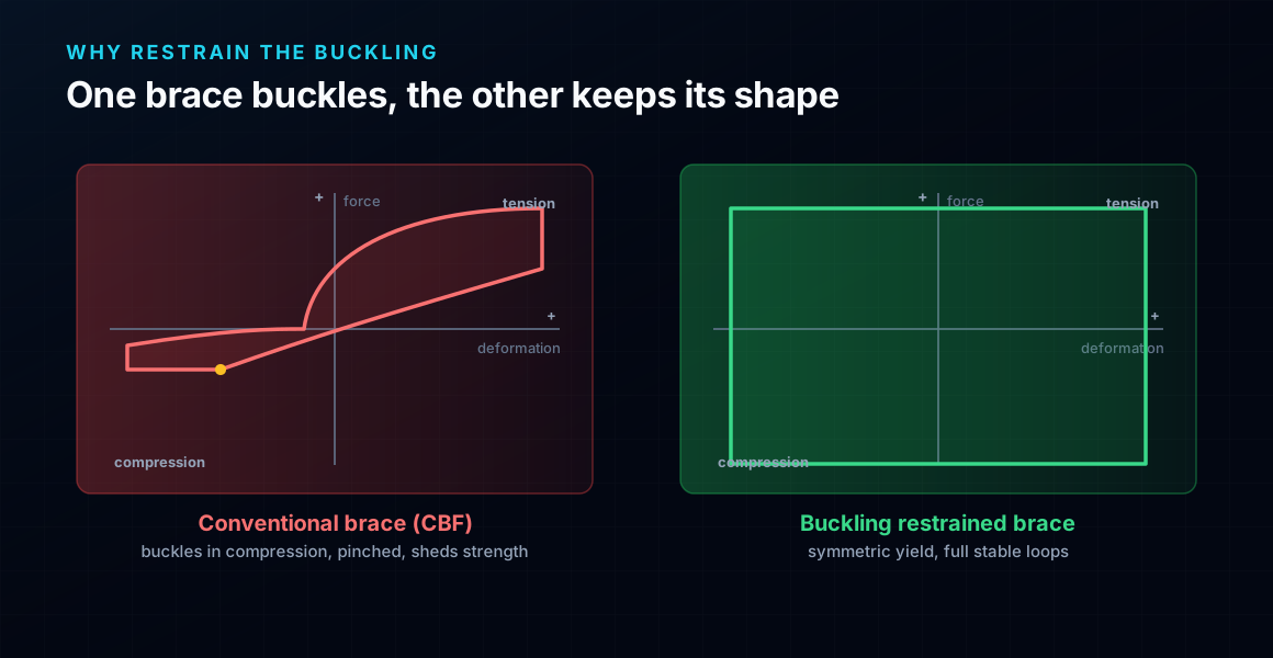
Why go to the trouble? Compare the three ways to brace a bay. A moment frame is ductile but flexible, so drift control is expensive. A concentrically braced frame (CBF) is stiff, but its diagonal buckles in compression: usable compression strength drops with slenderness, the buckled brace sheds load, and the hysteresis is pinched and unequal in the two directions. The BRBF keeps the stiffness of a diagonal but removes the buckling, so the loop is full and symmetric. Against an eccentrically braced frame, which yields a link in the beam, the BRBF yields the brace and leaves the beam alone.
The buckling the casing removes is exactly the Euler buckling that governs a slender strut. New to it? Our column buckling piece sets the scene. Here we go straight to the number that governs the BRBF.
The core is the fuse: capacity design in one picture
The organising principle of BRBF design is capacity design: pick one element to be the weak link, and make everything else strong enough to stay elastic while that element yields fully and strain-hardens. In a BRBF the fuse is the steel core, and its axial yielding is deliberately the weakest mechanism in the frame.
This is why BRBFs behave so well. A steel core yielding in pure axial tension and compression is about as stable and repeatable an energy dissipator as exists, provided it cannot buckle. The casing guarantees that, so the core delivers dozens of full cycles without losing strength. Nothing has to buckle first, unlike the diagonal of a CBF.
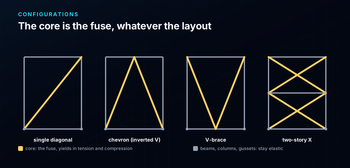
The core is the fuse in every configuration: a single diagonal, a chevron (inverted V), a V-brace, or a two-story X. Only the geometry that feeds the core changes. One configuration deserves a warning, though: in a chevron the two braces meet the beam at midspan, and because the core is stronger in compression than in tension (more on that below), the beam must carry an unbalanced vertical force when one brace yields before the other. That beam check is unique to BRBF chevrons and is a common miss.
The criterion behind the code, from first principles
Take a conventional compression brace first. Its usable strength is governed by buckling: φcPn = φcFcrAg, and the critical stress Fcr collapses as the slenderness KL/r grows, down the Euler curve. To carry a given compression the brace must be oversized, and even then it buckles under cyclic load and degrades. That collapse is the whole problem the BRB solves.
Now restrain the buckling. If the casing holds the core straight, the core never reaches Fcr; it simply yields. So the usable strength is the yield strength, flat, with no slenderness reduction:
φPysc = φ Fysc Asc (no Fcr, no KL/r)
That is the criterion behind the code: a BRB is designed on the yield of its core area Asc, the same value in tension and compression. The core area is to a BRBF what the link length is to an EBF, the one number the whole design turns on. In exchange the code asks two things. First, the restraint rule: the casing must actually prevent buckling, so its elastic (Euler) buckling load must beat the core yield with margin,
Pe,casing / Pysc ≥ 1.5
a limit that traces back to Watanabe's work on restrainer stability. Second, capacity design of everything outside the core for the strain-hardened forces the yielding core actually delivers. Miss either and the word restrained stops being true.
The strengths you need: Pysc and the adjusted forces
Three axial strengths run the whole design, and all three come from the core area. The first is the yield strength, which sets the design check:
Pysc = Fysc Asc, design strength φPysc with φ = 0.90
The other two are the adjusted brace strengths: the real force the strain-hardened core pushes into the rest of the frame at the design deformation. They come from a qualifying cyclic test, not from a table, and they are what capacity design uses:
- Tension: ω Ry Pysc, where ω is the strain-hardening adjustment factor, the ratio of the tested tension force at the 2Δbm amplitude to the yield force.
- Compression: β ω Ry Pysc, where β ≥ 1.0 is the compression strength adjustment factor. A BRB is a little stronger in compression than in tension, because the core bulges by Poisson effect against the mortar and picks up friction. That β is why a chevron beam sees an unbalanced load.
So the backbone is anchored at Pysc and fanned out by ω and β. Get those three numbers and every other check follows. Next we put numbers to them.
Worked check, part 1: size the steel core
The bay and the demand
Take a single-diagonal BRB in a bay L = 6.0 m wide and h = 3.5 m tall, so the brace runs at α = 30.3° over a work-point length Lwp = 6.95 m (cos α = 0.864). A single diagonal in a pinned bay is statically determinate for lateral load, so the brace takes the whole story shear. For a design story shear Vu = 500 kN:
Pu = Vu / cos α = 500 / 0.864 = 579 kN
Size the core
The core is a flat plate of low-yield steel, Fysc = 250 MPa. Because buckling is restrained, the same area works in tension and compression, so the sizing is a one-line yield check, φFyscAsc ≥ Pu:
Asc ≥ Pu / (φ Fysc) = 579·10³ / (0.90 · 250) = 2573 mm²
Provide a 25 × 110 mm core, Asc = 2750 mm². Then Pysc = 250 · 2750 = 688 kN, and φPysc = 0.90 · 688 = 619 kN ≥ 579 kN, a utilisation of 94 %.
Feel the size of that win: a conventional CBF diagonal carrying the same 579 kN in compression would need a section several times larger to keep Fcr up at this length, and it would still buckle and pinch under cyclic load. The BRB carries it on 2750 mm² of core, tension and compression alike. That is the criterion doing its work.
Worked check, part 2: the core strain and ductility demand
Sizing the core for strength is only half the criterion. The other half is deformation: the core must be able to yield through the strain the frame imposes at the design drift, and it must have been tested that far. This is where a strong-enough core can still fail, and it often governs the core length.
Start from the design story drift. Take a drift ratio of 2.0 %, so Δstory = 0.020 · 3500 = 70 mm. The axial deformation the diagonal sees is the drift projected along the brace:
Δbm = Δstory · cos α = 70 · 0.864 = 60.5 mm
This deformation is taken up almost entirely by the yielding core length, Lysc = 4.60 m here (the end zones are stiffened and stay elastic). The core strain at the design drift is therefore
ε = Δbm / Lysc = 60.5 / 4600 = 1.31 %
The code qualifies a brace to 2Δbm, so the tested strain is 2 · 1.31 % = 2.63 %, inside the range real BRBs certify (roughly 3 %). Against the core yield deformation Δy = (RyFysc/E)·Lysc = 6.3 mm, the ductility is μ = 60.5 / 6.3 = 9.6 at the design drift and about 19 at the test amplitude, well within the cumulative ductility (≥ 200) a qualified brace delivers.
The trap mirrors the EBF link: shortening the yielding length raises the strain. Halve Lysc and the strain doubles past the tested range, so the core length has a floor set by the qualified strain, not just a strength requirement.
See it yourself: watch the buckling a BRB removes
The whole case for a BRB is the collapse of φcFcr with slenderness, and you can watch it happen. In the calculator below, take a plain steel compression member and push its length up: the critical load falls down the Euler curve, and the usable compression strength with it. That falling curve is precisely what the casing deletes.
A buckling-restrained core carries Pysc flat across that same range, no matter how slender the core plate is, because it never gets to buckle. Read more in Euler buckling explained, then come back and size the core against the yield check above.
End conditions (buckling case)
Pinned – Pinned
Cross-section
Slenderness KL/r
134.7
limit 200 · OK
Euler Pcr (elastic)
310.7 kN
Fe = 108.9 MPa
AISC 360 φcPn
245.2 kN
Fcr = 95.5 MPa · elastic
NBR 8800 Nc,Rd
247.7 kN
χ = 0.382 · λ₀ = 1.52
Code vs code — same column
Nc,Rd / φcPn = 1.010
Both codes share the 0.658 / 0.877 buckling curve — the ~1% gap is purely φc = 0.90 (AISC) vs 1/γa1 = 0.909 (NBR).
Demand check — Nd = 150 kN
Step-by-step derivation — live for YOUR column
IPE 200 · L = 3 m · K = 1 · fy = 250 MPa
- 1
Slenderness ratio
λ = K·L/r = 1 × 3000 / 22.28 mm
λ = 134.7 (≤ 200 ✓)
- 2
Euler elastic buckling stress and load
Fe = π²E/λ² = π² × 200,000 / 134.7² · Pcr = Fe·A = Fe × 2854 mm²
Fe = 108.9 MPa · Pcr = 310.7 kN
- 3
Buckling regime (AISC E3)
4.71·√(E/fy) = 4.71·√(200,000/250) = 133.2 < λ = 134.7
elastic buckling → use E3-3 (0.877·Fe)
Elastic range: capacity no longer depends on fy — only geometry (r, K, L) helps.
- 4
AISC 360 critical stress and design capacity
Fcr = 0.877 · Fe = 0.877 × 108.9 = 95.5 MPa · φcPn = 0.9 × Fcr × A
Pn = 272.5 kN · φcPn = 245.2 kN
- 5
NBR 8800 reduction factor and design capacity
λ₀ = √(fy/Fe) = 1.515 > 1.5 → χ = 0.877/λ₀² = 0.382 · Nc,Rd = χ·A·fy/1.1
Nc,Rk = 272.5 kN · Nc,Rd = 247.7 kN
Same 0.658/0.877 curve as AISC — the ~1% difference is φc = 0.90 vs 1/γa1 = 0.909.
Sections that work — 3 lightest of 612 catalog profiles carrying Nd = 150 kN at L = 3 m, K = 1
| Section | kg/m | φcPn (kN) | Nc,Rd (kN) | Util. | |
|---|---|---|---|---|---|
| lightestSHS 80x4 | 9.2 | 164 | 166 | 91% | |
| HSS 76x76x4.8 | 9.9 | 165 | 167 | 91% | |
| CHS 88.9x5 | 10.3 | 172 | 174 | 87% |
Pass criterion: φcPn ≥ Nd (AISC 360 LRFD) AND Nc,Rd ≥ Nd (NBR 8800) AND KL/r ≤ 200, using each section's tabulated-mass area and minimum radius of gyration.
Buckling curve — IPE 200, fy = 250 MPa
Capacity of IPE 200 by unbraced length — K = 1, fy = 250 MPa
| L (m) | KL/r | Pcr Euler (kN) | φcPn AISC (kN) | Nc,Rd NBR (kN) | Regime |
|---|---|---|---|---|---|
| 1 | 45 | 2,796 | 577 | 583 | inelastic |
| 2 | 90 | 699 | 419 | 423 | inelastic |
| 3◀ yours | 135 | 311 | 245 | 248 | elastic |
| 4 | 180 | 175 | 138 | 139 | elastic |
| 5 | 224 ⚠ | 112 | 88 | 89 | elastic |
| 6 | 269 ⚠ | 78 | 61 | 62 | elastic |
| 7 | 314 ⚠ | 57 | 45 | 45 | elastic |
| 8 | 359 ⚠ | 44 | 34 | 35 | elastic |
| 9 | 404 ⚠ | 35 | 27 | 28 | elastic |
| 10 | 449 ⚠ | 28 | 22 | 22 | elastic |
Worked check, part 3: where the demand comes from
Strength and strain both check out, but where does the demand Pu come from? Here a BRBF is simpler than an EBF. An EBF bay is statically indeterminate, so its link force needs a frame analysis. A single-diagonal BRBF bay with pinned ends is statically determinate for lateral load: the diagonal is the only lateral load path, so it carries the entire story shear and the axial force follows from equilibrium alone.
- Brace axial: Pu = Vu / cos α = 500 / 0.864 = 579 kN, no analysis needed.
- Column axial from the brace: the vertical component Pu · sin α = 579 · 0.504 = 292 kN is delivered into the column, part of the overturning couple.
- Global equilibrium: the base reactions balance the applied shear (ΣFx = 500 kN) and the overturning moment Vu·h = 1750 kN·m, a quick sanity check.
For a chevron or a two-story X the split is set by symmetry rather than a single load path, but the principle holds: the braces share the story shear, and the core force is transparent. That determinacy is a feature, it is why a BRBF demand is easy to hand-check where an EBF is not.
Protecting the rest: capacity design
The core is the fuse; capacity design makes sure it is the only fuse. Every other element must survive the core not merely yielding but strain-hardening well past Pysc. That is what the adjusted brace strengths are for. With ω = 1.5, β = 1.1 and Ry = 1.1:
- Tension delivered: ω Ry Pysc = 1.5 · 1.1 · 688 = 1134 kN.
- Compression delivered: β ω Ry Pysc = 1.1 · 1134 = 1248 kN, about 2.16× the design demand of 579 kN.
- The connections, gusset plates, beam and columns are all designed for these forces, not for the elastic load-case demand. The gusset also has its own buckling check, since it now carries 1248 kN in compression.
- In a chevron, the beam must carry the vertical unbalance between the compression and tension braces, roughly (βω − ω)RyPysc·sin α ≈ 57 kN downward at midspan for this core, plus the full brace push, without forming a hinge.
Codes: this follows AISC 341-16 §F4, and crucially §K3, which requires the brace to be qualified by project-specific cyclic testing, that is where ω and β come from. Seismic demand parameters (R, Cd, Ω0) come from ASCE/SEI 7. In Brazil member design follows NBR 8800 and seismic detailing NBR 15421; demand is low across most of the country, but the BRB capacity-design logic is identical wherever the load comes from.
Common mistakes & FAQ
The mistakes that most often turn a textbook-correct BRBF into a failed check:
- Designing the connection for the analysis force. The gusset, beam and columns are sized for the adjusted strengths (βωRyPysc ≈ 1248 kN here), not the 579 kN load-case demand. This is the single most common BRBF error.
- Forgetting β. A BRB is stronger in compression than in tension. Ignore β and the chevron beam unbalance and the compression-side connection are under-designed.
- Skipping the restraint check. If Pe,casing / Pysc falls below about 1.5, the casing does not actually restrain the core and the brace buckles like a plain diagonal. The word restrained has to be earned.
- Using an unqualified brace. AISC 341 §K3 wants project-specific cyclic test data; ω and β are measured, not looked up. A BRB is a tested assembly, usually proprietary, not a rolled shape.
- Exceeding the tested core strain. Too short a yielding length pushes the strain past what the brace was qualified to. Check ε at 2Δbm against the test.
- Applying an Fcr reduction to the core. That double-counts a buckling that cannot happen. The core is designed on yield, full stop.
FAQ
Is a BRBF better than an EBF? Different fuses. A BRB yields the brace and leaves the beam undamaged and easy to inspect or replace; an EBF yields a link in the beam. BRBFs give near-symmetric behaviour and simple, determinate demands; EBFs need no proprietary tested brace. Many designers pick BRBFs for the replaceable, tested fuse.
Why is a BRB stronger in compression than in tension? Under compression the core shortens and thickens (Poisson effect) and bears on the mortar, so friction and confinement add force. That is the β factor, typically 1.05 to 1.15.
Can I use a BRBF where seismic demand is low, like most of Brazil? Yes. The capacity-design logic applies to any lateral load. In low-seismic zones the demand is small, but a BRBF's stiffness plus clean, replaceable ductility can still be the efficient choice.
Key takeaways
A buckling restrained braced frame is one idea executed carefully: put the ductile fuse inside the diagonal, restrain it so it cannot buckle, and protect everything around it.
- The criterion is no buckling penalty: the core is designed on yield, φFyscAsc ≥ Pu, the same area in tension and compression. The core area is the one number the design turns on.
- You earn that with the restraint rule, Pe,casing/Pysc ≥ 1.5 (ours 1.62), and by capacity design for the adjusted strengths ωRyPysc = 1134 kN and βωRyPysc = 1248 kN.
- Our 25 × 110 mm core: Pu = 579 kN, φPysc = 619 kN (94 %), core strain 1.31 % at the design drift and 2.63 % at 2Δbm, ductility μ = 9.6, all hand-checked.
- The demand is determinate: a single-diagonal BRBF carries Pu = Vu/cos α with no frame analysis, unlike the indeterminate EBF link.
Want to try the numbers on your own brace? The column buckling calculator and the full CalcSteel editor are free to use, and CalcSteel is free for students. Size the core, check the restraint ratio, and watch the buckling a BRB makes irrelevant.
Sources
- 1.AISC 341-16, Seismic Provisions for Structural Steel Buildings (§F4, BRBF)
- 2.AISC 341-16 §K3, Qualifying Cyclic Tests of Buckling-Restrained Braces
- 3.ASCE/SEI 7, Minimum Design Loads and Associated Criteria (seismic R, Cd, Ω0)
- 4.Sabelli, Mahin & Chang, Seismic demands on steel braced-frame buildings with buckling-restrained braces (Engineering Structures, 2003)
- 5.ABNT NBR 8800 / NBR 15421, Projeto de estruturas de aço e resistência sísmica
Try CalcSteel for free
Model, analyze and design steel structures in your browser. No install, no signup.
Open the 3D editor