Why the Pfizer Tower's Columns Buckled (Case Study)
In July 2026, two steel columns on the 21st floor of the former Pfizer headquarters at 235 East 42nd Street in Manhattan began to buckle, sagging the floors and forcing evacuations. This is a structural-engineering breakdown of column buckling — what it is, why added load and a missed reinforcement pushed a safe column past its limit, and how we reproduce the numbers with a real FEM engine and AISC 360.
Key takeaways
- Column buckling is a stability failure, not a strength failure: a slender member goes sideways long before the steel is crushed.
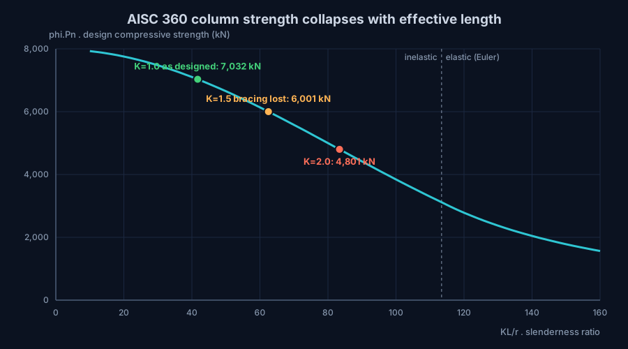
- Capacity falls with the square of effective length. For our real column, losing bracing (K: 1.0 to 1.5) drops the AISC design strength by 32%, from 7,033 kN to 6,000 kN.
- The Pfizer column failed from two compounding causes: extra floors raised the axial demand, and the reinforcement that would have restored capacity was missed.
- We reproduce every number with the shipping CalcSteel FEM engine plus AISC 360 Chapter E: a UC 356x368x202 at util 0.81, pushed to 1.13 by the added load and a longer effective length.
- The lesson for engineers: when you add load, re-check stability (not just strength), watch the effective length during construction, and never skip the reinforcement the new load path demands.
A skyscraper that started to fold
On the morning of 7 July 2026, construction crews inside the former Pfizer world headquarters at 235 East 42nd Street in Midtown Manhattan found something no one wants to see: two structural steel columns on the 21st floor were bowing sideways, and the floors around them had sagged by as much as four inches. The 37-storey tower, being gutted and converted into luxury apartments, was evacuated along with several neighbours as officials warned of a possible partial collapse.
The building did not fall. Emergency jacks and new steel shoring stabilised the weakest points within hours, and an inquiry was opened days later. But the incident is a textbook lesson in the one failure mode that scares structural engineers the most, because it gives almost no warning: column buckling. This article rebuilds the physics behind it, and reproduces the numbers on a real steel column using the CalcSteel FEM engine and AISC 360.
What actually happened at 235 East 42nd Street
The tower, built in 1961 as Pfizer's headquarters, was being converted from offices to roughly 660 rental apartments. According to the developer, the project was adding around 18,000 square feet across 15 of the upper floors - new slabs, partitions and finishes that a 1960s office frame was never designed to carry.
That extra weight is the trigger. The developer told reporters that the additional load placed on the upper floors caused two particular columns on the 21st floor to bend. Engineers who inspected the frame added a second cause: the columns had buckled essentially from not having been properly reinforced, or having been missed in the reinforcement process - the strengthening those columns needed for the new loads was not there.
The response was immediate: hydraulic jacks to arrest the movement, then new steel members welded in to shore up the load path. Four nearby buildings stayed evacuated while the shoring went in. Below, we show why a column that had stood safely for sixty years could reach this point - and how close the margins really are.
What column buckling actually is
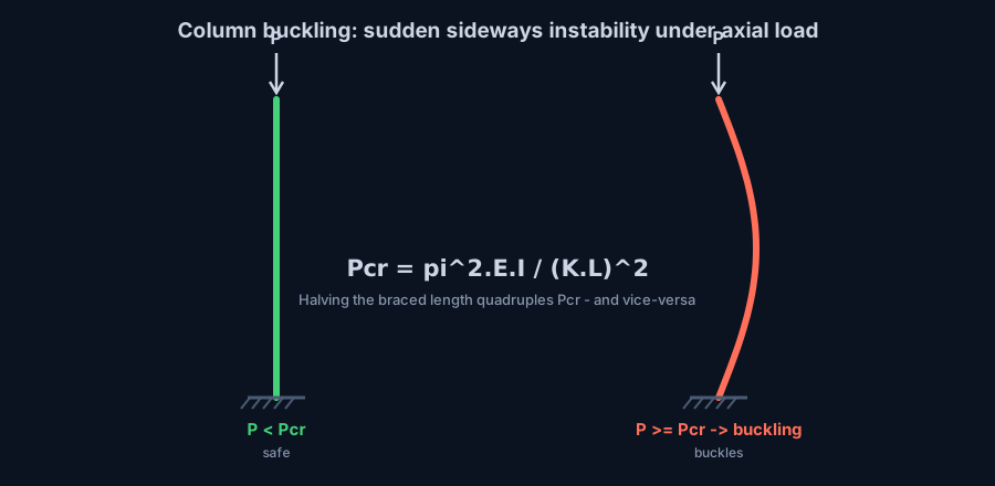
Push down on a short, stocky block of steel and it fails by crushing - the material yields. Push down on a long, slender column and something very different happens: at a certain load it suddenly bows sideways and loses almost all of its capacity, while the steel itself is still far below its yield stress. That is buckling - a stability failure, not a strength failure.
The critical load was derived by Leonhard Euler in 1757: Pcr = pi squared times E times I, divided by (K times L) squared. Three things make a column strong against buckling: a stiff material (E), a fat, spread-out section (the moment of inertia I), and short unbraced length. The effective length factor K captures how the ends are held - and, as we will see, it is the term that most often bites in real buildings. For the theory in full, see our companion guide on Euler buckling and AISC design.
The two levers: demand versus capacity
Every column check is a race between two numbers. Demand is the axial force the column must carry - the weight of everything above it, funnelled down through the frame. Capacity is how much that column can take before it buckles or yields. Design codes such as AISC 360 Chapter E turn Euler's elastic load into a real design strength phi.Pn by adding an inelastic transition (stocky columns yield before they reach the Euler load) and a resistance factor phi = 0.90.
A safe column keeps demand comfortably below capacity - a utilisation ratio under 1.0. The Pfizer failure is what happens when a renovation moves both levers the wrong way at once: it raises demand by adding floors, and it lowers capacity by leaving out reinforcement and by lengthening the effective span during construction. Let us put real numbers on it.
Worked example, part 1: the column's real capacity
Take a heavy building column: a UC 356x368x202 (a universal column, 375 mm deep, 202 kg/m, area 257 cm squared) in grade 345 MPa steel, with a 4.0 m storey height. We ran it through the CalcSteel FEM engine and the built-in AISC 360 Chapter E check. As designed, with the floors bracing the column at every level (effective length factor K = 1.0):
- Slenderness KL/r = 41.7 (stocky - it will buckle inelastically, below the Euler load)
- Critical stress Fcr = 304 MPa, versus a yield of 345 MPa
- Design strength phi.Pn = 7,033 kN
For comparison, the pure elastic Euler load for this column is 29,222 kN - more than four times higher. That gap is exactly why codes cannot use Euler directly: real columns of this stockiness yield and lose stiffness long before the elastic load, so AISC caps the strength at phi.Pn = 7,033 kN. The curve below shows how that design strength falls as the column gets slenderer.
Worked example, part 2: how added floors overload it
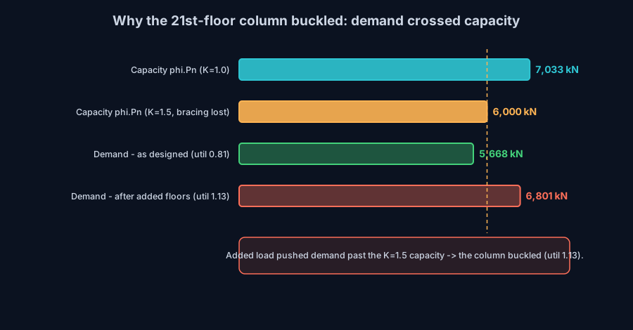
Now the demand. Our 21st-floor column carries the sixteen floors above it. With a tributary area of about 36 square metres per floor and a factored load of roughly 9.8 kN per square metre (LRFD 1.2 dead + 1.6 live), each floor adds about 354 kN. Sixteen floors give a design demand of Nd = 5,668 kN.
Against a capacity of 7,033 kN, that is a utilisation of 0.81 - safe, with headroom, exactly as a 1960s office column should be. Then the renovation adds new slabs and finishes across the upper floors. Model that as roughly a 20% increase in the axial load reaching this column and the demand climbs to Nd = 6,801 kN. Utilisation is now 0.97 - still just under 1.0 at K = 1.0, but the safety margin is essentially gone. The column is now one bad assumption away from failure. It got two.
Run your own column: the live buckling calculator
The numbers above are not a spreadsheet - they come from the same engine that powers the calculator below. Enter a profile, a length and the end conditions, and it returns the elastic critical load, the slenderness and the AISC design strength phi.Pn in real time. Try changing the effective length factor K from 1.0 to 2.0 and watch the capacity collapse - that single input is the difference between the Pfizer column standing and folding.
End conditions (buckling case)
Pinned – Pinned
Cross-section
Slenderness KL/r
134.7
limit 200 · OK
Euler Pcr (elastic)
310.7 kN
Fe = 108.9 MPa
AISC 360 φcPn
245.2 kN
Fcr = 95.5 MPa · elastic
NBR 8800 Nc,Rd
247.7 kN
χ = 0.382 · λ₀ = 1.52
Code vs code — same column
Nc,Rd / φcPn = 1.010
Both codes share the 0.658 / 0.877 buckling curve — the ~1% gap is purely φc = 0.90 (AISC) vs 1/γa1 = 0.909 (NBR).
Demand check — Nd = 150 kN
Step-by-step derivation — live for YOUR column
IPE 200 · L = 3 m · K = 1 · fy = 250 MPa
- 1
Slenderness ratio
λ = K·L/r = 1 × 3000 / 22.28 mm
λ = 134.7 (≤ 200 ✓)
- 2
Euler elastic buckling stress and load
Fe = π²E/λ² = π² × 200,000 / 134.7² · Pcr = Fe·A = Fe × 2854 mm²
Fe = 108.9 MPa · Pcr = 310.7 kN
- 3
Buckling regime (AISC E3)
4.71·√(E/fy) = 4.71·√(200,000/250) = 133.2 < λ = 134.7
elastic buckling → use E3-3 (0.877·Fe)
Elastic range: capacity no longer depends on fy — only geometry (r, K, L) helps.
- 4
AISC 360 critical stress and design capacity
Fcr = 0.877 · Fe = 0.877 × 108.9 = 95.5 MPa · φcPn = 0.9 × Fcr × A
Pn = 272.5 kN · φcPn = 245.2 kN
- 5
NBR 8800 reduction factor and design capacity
λ₀ = √(fy/Fe) = 1.515 > 1.5 → χ = 0.877/λ₀² = 0.382 · Nc,Rd = χ·A·fy/1.1
Nc,Rk = 272.5 kN · Nc,Rd = 247.7 kN
Same 0.658/0.877 curve as AISC — the ~1% difference is φc = 0.90 vs 1/γa1 = 0.909.
Sections that work — 3 lightest of 612 catalog profiles carrying Nd = 150 kN at L = 3 m, K = 1
| Section | kg/m | φcPn (kN) | Nc,Rd (kN) | Util. | |
|---|---|---|---|---|---|
| lightestSHS 80x4 | 9.2 | 164 | 166 | 91% | |
| HSS 76x76x4.8 | 9.9 | 165 | 167 | 91% | |
| CHS 88.9x5 | 10.3 | 172 | 174 | 87% |
Pass criterion: φcPn ≥ Nd (AISC 360 LRFD) AND Nc,Rd ≥ Nd (NBR 8800) AND KL/r ≤ 200, using each section's tabulated-mass area and minimum radius of gyration.
Buckling curve — IPE 200, fy = 250 MPa
Capacity of IPE 200 by unbraced length — K = 1, fy = 250 MPa
| L (m) | KL/r | Pcr Euler (kN) | φcPn AISC (kN) | Nc,Rd NBR (kN) | Regime |
|---|---|---|---|---|---|
| 1 | 45 | 2,796 | 577 | 583 | inelastic |
| 2 | 90 | 699 | 419 | 423 | inelastic |
| 3◀ yours | 135 | 311 | 245 | 248 | elastic |
| 4 | 180 | 175 | 138 | 139 | elastic |
| 5 | 224 ⚠ | 112 | 88 | 89 | elastic |
| 6 | 269 ⚠ | 78 | 61 | 62 | elastic |
| 7 | 314 ⚠ | 57 | 45 | 45 | elastic |
| 8 | 359 ⚠ | 44 | 34 | 35 | elastic |
| 9 | 404 ⚠ | 35 | 27 | 28 | elastic |
| 10 | 449 ⚠ | 28 | 22 | 22 | elastic |
Failure cause 1: the reinforcement that was missed
When you add load to an existing column, the honest fix is to add capacity - typically by welding steel cover plates to the flanges, which increases both the area and the radius of gyration. In our example, jacketing the column up to the equivalent of a UC 356x406x287 raises the design strength to about 10,166 kN. The renovated demand of 6,801 kN would then sit at a utilisation of just 0.67 - comfortably safe.
That reinforcement is exactly what the inspecting engineers said was missed at 235 East 42nd Street. Without it, capacity stayed at 7,033 kN while demand climbed to 6,801 kN. On paper the column was still (barely) passing at K = 1.0. But a renovation rarely leaves the second variable - the effective length - untouched.
Failure cause 2: a longer effective length
A column is only as short as its bracing makes it. In a finished building, the floor slabs and beams hold each column at every level, so K = 1.0. During a gut renovation, though, slabs get demolished, beams get disconnected, and temporary conditions can leave a column laterally unheld over two storeys - its effective length doubles locally and K climbs toward 1.5 or 2.0.
Watch what that does. Raising K from 1.0 to 1.5 drops our column's design strength from 7,033 kN to 6,000 kN - a 32% loss, with no change to the steel. The renovated demand of 6,801 kN now exceeds capacity: utilisation jumps to 1.13. That is buckling. The floors sag; the columns bow sideways; the margin is gone. This is why the effective length factor K deserves obsessive attention - see our deep dive on the K factor in column design.
Why construction is the dangerous moment
The Pfizer column had stood for sixty years. It failed not in service but mid-renovation - and that is no coincidence. During construction, the structure passes through temporary states that no one lives in but every column still has to survive: bracing removed before its replacement is in, fresh concrete loading a frame that is not yet complete, loads arriving out of the sequence the designer assumed.
Slender columns under rising axial load are also where second-order effects bite hardest: as the column bows, the axial load acts on the growing lateral offset and amplifies the very deflection that caused it (the P-delta effect). A first-order strength check can pass while the real, deformed structure is already unstable. When you add load to an existing frame, the construction sequence itself must be checked - see second-order P-delta effects in steel frames.
The engineering lessons
- Adding load means re-checking stability, not just strength. A column that passes a yield check can still buckle. Every added slab, HVAC unit or partition changes the axial demand on the columns below.
- Reinforcement is not optional when the load path changes. If the new demand exceeds capacity, cover plates or jacketing must go in - and be verified - before the load arrives.
- Guard the effective length during construction. Never remove bracing without a temporary substitute; a column unheld over two floors can lose a third of its strength.
- Model the whole load path. Buckling is a system behaviour: it depends on how every beam and brace restrains every column. A member-by-member spreadsheet misses it; a frame model does not.
Common mistakes that hide a buckling risk
- Assuming K = 1.0 always. Sway frames, missing bracing and construction stages routinely push K above 1.0 - and capacity falls with K squared.
- Checking strength but not stability. phi.Fy.Ag looks generous; the buckling strength phi.Pn can be a fraction of it for a slender column.
- Ignoring the construction sequence. The governing load case is often a temporary state, not the finished building.
- Forgetting second-order effects. A first-order analysis of a slender, heavily loaded column is optimistic; P-delta can tip a passing check into failure.
- Trusting tributary-area shortcuts. Load that redistributes through a frame does not always follow the neat tributary rectangle a hand calc assumes.
Key takeaways
The Pfizer tower did not fall, and the engineers who caught the bowing columns and shored them deserve credit. But the near-miss is a clear warning. A steel column is a stability problem, not just a strength problem: its capacity can be halved by a factor - the effective length - that never shows up in the weight of steel. When a renovation adds load, the safe margin that took decades to earn can vanish in a single construction stage.
Model the frame, check the buckling strength to your code, and re-run it every time the load or the bracing changes. You can do all of that - AISC 360, Eurocode 3 or NBR 8800, with a real FEM solver - free in the browser at CalcSteel.
Sources
Try CalcSteel for free
Model, analyze and design steel structures in your browser. No install, no signup.
Open the 3D editor