Brooklyn Bridge Engineering: How It Really Works
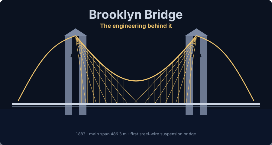
Brooklyn Bridge engineering, from the pneumatic caissons under its towers to the stiffening truss, the suspension cables, and a factor of safety of six: every number verified in a real FEM engine plus a free beam calculator.
Key takeaways
- It is a hybrid of three redundant load paths — suspension cables, diagonal stays, and a deck stiffening truss — which is the root of its famous robustness.
- The towers stand on pneumatic caissons, not bedrock. Washington Roebling sank the Manhattan caisson to 78.5 ft, where compressed air reached 35 psi (240 kPa, exactly p = ρgh), then stopped in firm sand rather than dig on to rock, because caisson disease was crippling his crews. 140+ years without settlement proved the call right.
- The deck behaves as a beam: our representative girder saw +200 kN·m under self-weight (wL²/8) and +240 kN·m from a 120 kN crossing load (PL/4) — moving concentrated loads govern.
- Depth equals stiffness: a deep W610x125 deflected 7.0x less than a shallow W360x51 under identical load (δ ∝ 1/I), tracking its 7.0x larger moment of inertia.
- Continuity redistributes moment: a two-span continuous deck gives −200 kN·m hogging over the tower and +112.5 kN·m in the spans — statically indeterminate, solved instantly by FEM.
- Safety factors exist for the unknowns: the deck girder ran at utilization 0.30 (FoS 3.32 on first yield); Roebling's cables were designed to six and survived wire fraud down to about five.
Brooklyn Bridge Engineering — how the world's most famous bridge actually works
In 1883, the longest suspension bridge on Earth was completed from the drawings of a man who had already been dead for fourteen years, under a chief engineer too sick to leave his bedroom, steered day to day by his wife. And it still carries traffic across the East River more than 140 years later.
That is not marketing hyperbole — it is the literal history of the Brooklyn Bridge. John A. Roebling designed it, died in 1869 before a single stone was laid, and left the work to his son Washington Roebling, who was then crippled by decompression sickness contracted in the pressurized foundation caissons. His wife, Emily Warren Roebling, learned the mathematics of cable statics and materials, relayed his instructions to the site, and effectively ran the engineering for over a decade. The bridge opened on 24 May 1883 as the longest suspension bridge in the world, with a main span of 486.3 m (1,595.5 ft).
This is a case study for engineers. We are going to take the bridge apart the way a structural engineer would — the three load paths, the deck that behaves like a beam, the deflection that separates a stiff structure from a doomed one, and the famous factor of safety of six — and then we are going to reproduce the deck's numbers with a real FEM engine. Every worked value below comes out of CalcSteel's shipping finite-element solver, validated against closed-form theory to three decimals, and you can drive the same live beam calculator yourself, for free, right here in the article.
A word of honesty up front: the worked examples are a representative modern-steel model of how the Roebling stiffening truss behaves as a beam. They are not the exact 1883 members — nobody is going to re-derive a nineteenth-century wrought-iron truss to three decimals. What they do capture is the physics that made the bridge work, in numbers you can check. If you are a student, this is the clearest possible bridge between a textbook diagram and a real structure. If you are a practicing engineer, it is a reminder of why the fundamentals never went out of date.
Three structural systems in one bridge
Most bridges pick a structural type and commit to it. The Brooklyn Bridge does not — it is a hybrid, and that is the single most important thing to understand about how it works. Roebling combined three distinct structural systems, each capable of carrying load on its own, into one deck. Engineers call this redundancy, and it is the reason the bridge is famously robust.
The three load paths are:
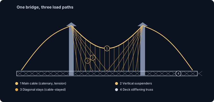
- The suspension system — the primary structure. Four main cables sweep in a catenary curve from anchorage to tower to anchorage, working purely in tension. From them hang the vertical suspenders that pick up the deck at regular intervals and carry its weight up into the cables and down into the masonry towers and anchorages. Each of the four cables is about 0.4 m (15.75 in) in diameter and bundles more than 5,000 galvanized steel wires.
- The diagonal stay cables — the striking fan of straight cables that radiate downward from the tops of the towers directly to the deck. This is a cable-stayed element grafted onto a suspension bridge. Its job is to stiffen the deck against local dips and gusts. Later analysis judged the stays to be not strictly necessary for strength, but Roebling kept them for the stiffness they add — and for their unmistakable beauty.
- The deck stiffening truss — a deep trussed girder running the length of the deck at roadway level. It ties the suspender points together and distributes any concentrated load along the span so that no single suspender is overwhelmed. This is the member we will model as a beam in the worked examples.
Because load can travel to the towers by cable, by stay, or through the truss, no one path is a single point of failure. That is engineering redundancy in its purest historical form.
The bridge was also a genuine materials milestone: it was the first suspension bridge in the world to use steel wire in its cables. Earlier suspension bridges, including Roebling's own, had used iron. Steel's higher strength is exactly what allowed the record-setting 486.3 m main span. The two masonry towers — limestone and granite, rising about 84 m (276.5 ft) above high water — carry the cables with the pointed neo-Gothic arches that made the bridge an icon before anyone crossed it.
How the towers stand: the pneumatic caissons
The two masonry towers do not rest on the riverbed. Each one stands on a pneumatic caisson: a colossal upturned timber box, open at the bottom, sunk through the mud of the East River so the granite could be built on solid ground. It is the most extreme engineering on the whole project, and it is where the bridge nearly killed the man building it.
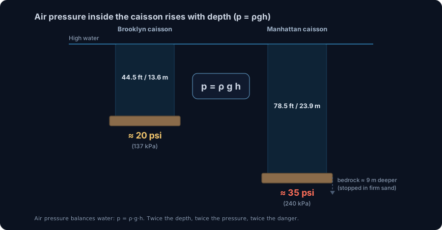
A caisson works like a drinking glass pushed upside down into water: trap air inside and the water is held out. Roebling's boxes were pumped full of compressed air so the workers, the sandhogs, could dig the riverbed by hand at the bottom and stay dry. As they excavated, the masonry piled on top drove the caisson steadily downward. The Brooklyn caisson measured 168 by 102 ft (51 by 31 m) in plan and was founded 44.5 ft (13.6 m) below high water. The Manhattan caisson, 172 by 102 ft, went far deeper, to 78.5 ft (23.9 m).
The physics that made it lethal. To keep the river out, the air pressure inside the caisson had to balance the water pressure pushing in at that depth. That is pure hydrostatics: p = ρ g h, the same relation behind every pressure calculation an engineer runs. Take the deeper Manhattan caisson, with brackish tidal water (ρ ≈ 1025 kg/m³) at h = 23.9 m:
- p = 1025 × 9.81 × 23.9 ≈ 240 kPa, about 2.4 atmospheres of gauge pressure, or roughly 35 psi.
That number is not a guess. It matches the 35 psi the crews actually recorded at the bottom of the Manhattan caisson, so the same p = ρgh you use for a water tank reproduces a measured fact from 1872 to the digit. Run the arithmetic for the shallower Brooklyn caisson at 13.6 m and you get only about 137 kPa (20 psi). The gap is the whole story: pressure grows in direct proportion to depth, and so does the amount of nitrogen forced into a worker's bloodstream. Come up too fast and it fizzes out as bubbles.
The result was caisson disease, the decompression sickness that divers call the bends. Between 25 January and 31 May 1872 the project physician treated 110 cases and three workers died. The chief engineer was among the wounded: Washington Roebling was left partially paralyzed by his own hours in the compressed air, which is exactly why Emily Warren Roebling ended up carrying his instructions to the site for the next eleven years (the timeline below picks up the human story).
The judgment call that defines an engineer. The Manhattan caisson had not reached rock: solid bedrock still lay about 9 m (30 ft) further down. But at 78.5 ft the compressed air was already maiming and killing the crews, and the dense, sandy subsoil under the caisson was firm. Roebling judged that the sand was strong enough to carry the tower, stopped digging, and filled the caisson with concrete in July 1872. It was a deliberate trade of a textbook ideal (found on rock) against a real, measured human cost. More than 140 years without meaningful settlement have proved the bearing judgment right. It is the clearest lesson on the bridge that engineering is not the pursuit of a perfect answer but the defensible balance of risk, and that a load path only has to reach competent ground, whether that ground is rock or well-proven sand.
The human story behind the numbers (1869–1884)
Before we touch a single moment diagram, it is worth walking the timeline — because the engineering decisions on this bridge are inseparable from the people who made them under extraordinary pressure.
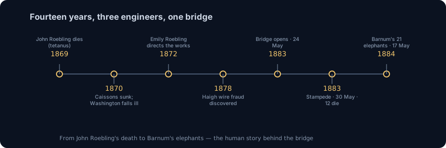
- 1869 — John A. Roebling dies. While surveying the tower location, a ferry crushed his foot; he died of tetanus a few weeks later, before construction began. The design was complete; the designer never saw a stone placed.
- 1870 onward — Washington Roebling takes over, then falls ill. His son became chief engineer. Directing work inside the pressurized foundation caissons, he was struck by caisson disease (decompression sickness, "the bends") and was left partially paralyzed, unable to visit the site.
- Through the 1870s — Emily Warren Roebling runs the works. Washington's wife became his indispensable link to the project, mastering the mathematics of cable statics and materials, carrying his detailed instructions to the engineers and contractors, and effectively directing the day-to-day engineering for more than a decade.
- 1878 — the wire fraud is discovered. Contractor J. Lloyd Haigh had been swapping inspected cable wire for rejected, inferior wire. By the time it was caught, the bad wire was already woven into the cables and could not be removed. (We return to how Roebling compensated in the factor-of-safety section.)
- 24 May 1883 — the bridge opens as the longest suspension bridge in the world after about fourteen years of construction. Roughly 20 or more workers had died building it.
- 30 May 1883 — the stampede. Six days after opening, on Memorial Day, a rumour spread through the crowd that the bridge was collapsing. The panic triggered a crush on a stairway that killed 12 people. The structure was never in danger; public confidence was.
- 17 May 1884 — Barnum's elephants. To reassure the public, showman P. T. Barnum led 21 elephants (along with 17 camels, with the celebrated Jumbo bringing up the rear) across the bridge — an informal, unforgettable live load test.
Keep that last image in mind. When we compute the bridge's margin of safety, remember that in 1884 its "proof load" was a parade of elephants — and it did not flinch.
Why the deck is really a beam
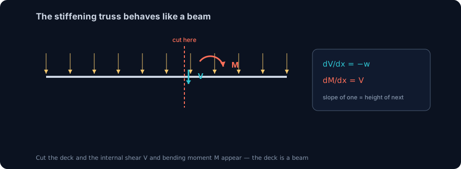
Here is the mental shift that unlocks the whole analysis: the stiffening truss and deck behave like a beam. Between suspender points and over the towers, the deck spans horizontally and resists load exactly the way a floor beam does — by developing internal forces along its length. Once you see the deck as a beam, every tool from a first structures course applies directly.
Two internal quantities describe that behaviour:
- Shear force, V — the internal vertical force that one slice of the deck transmits to the next. Think of it as how hard the beam is being "pushed past itself" at a given point. It is largest near the supports.
- Bending moment, M — the internal turning effect that puts one face of the deck in tension and the other in compression. It is what bends the beam, and it is what a section must be strong enough to resist. In a simply supported span it is largest near midspan.
These two are not independent — they are tied together by two elegant relations that hold for any beam under distributed load w:
- dV/dx = −w — the slope of the shear diagram equals minus the applied load intensity.
- dM/dx = V — the slope of the moment diagram equals the shear at that point.
In plain language: the slope of one diagram is the height of the next. Where the shear passes through zero, the moment reaches a peak. Where the load is heaviest, the shear falls off fastest. Master those two lines and you can sketch the internal forces of the Brooklyn Bridge deck — or any beam — from memory. We unpack them in detail in shear force and bending moment diagrams.
The best way to feel it is to draw one yourself. Our free beam calculator plots V, M, and deflection in real time as you change the span and loads — and in the next three sections we run exactly that engine on the deck. Watch how the two diagrams stay locked together: the moment peak always lands where the shear crosses zero.
Worked example 1: the deck under its own weight
Let's start where every bridge starts: holding itself up. Before a single pedestrian, cart, or elephant sets foot on the deck, the stiffening truss and floor system already carry a continuous, ever-present load — their own dead weight, spread evenly along the span. In beam terms that is a uniformly distributed load (UDL), and it is the cleanest place to see how a deck behaves as a beam.
To make this concrete, we built a representative modern-steel model of a Brooklyn-style deck floor-beam in CalcSteel and solved it with the real FEM engine. To be honest and precise: this is not one of the exact 1883 wrought-iron members — it is a deep steel girder (a W610x125, grade fy = 250 MPa, E = 200 GPa) chosen to reproduce, in numbers you can check, the way the real deck works structurally.
The model:
- Support: simply supported (a pin and a roller), the classic idealization of a deck bay spanning between two lines of suspenders.
- Span: L = 8 m.
- Load: uniform w = 25 kN/m along the whole length.
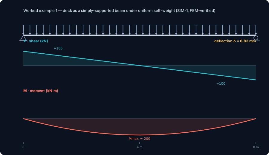
Here is what the engine returned — and every value matched closed-form beam theory to three decimals:
- Reactions: R = 100 kN at each support. That is simply the total load wL = 25 × 8 = 200 kN split evenly between two symmetric supports.
- Shear: the shear diagram is a straight line running from +100 kN at the left support, through zero at midspan, to −100 kN at the right. Peak shear Vmax = 100 kN, always at the supports — exactly where the deck hands its load off to the suspenders and towers.
- Bending moment: a smooth parabola, zero at both ends and peaking at midspan. Mmax = +200.0 kN·m, matching the textbook wL²/8 = 25 × 8² / 8 = 200 kN·m to the last digit.
- Deflection: the midspan sag is δ = 6.83 mm, tracking the classic 5wL⁴/384EI.
Two ideas are worth locking in. First, shear is largest at the supports, moment is largest at midspan — they peak in different places, which is why you always draw both diagrams, never just one. Second, the moment is what sizes the steel: 200 kN·m is the demand the girder must resist just to hold itself level. When the live load arrives in the next example, that number moves — and where it moves is the whole reason Roebling wrapped the deck in a stiffening truss.
Worked example 2: a heavy load crosses
Self-weight is polite: it sits still and spreads itself out. Traffic does not. In 1883 the live load was pedestrians, horse-drawn carriages, and cable cars; today it is trucks and buses. What matters structurally is that these loads are concentrated and they move — and a moving concentrated load asks a very different question of the deck than a smeared uniform one.
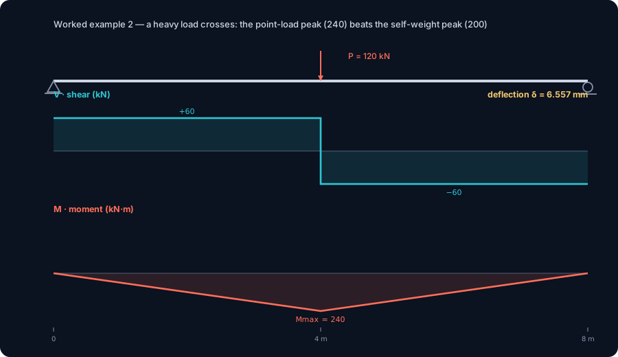
So we kept the exact same span and section — the W610x125, L = 8 m, simply supported — and replaced the distributed load with a single concentrated live load of P = 120 kN parked at midspan, the worst position for bending. Again the CalcSteel FEM engine solved it and matched closed-form theory to three decimals:
- Reactions: R = 60 kN at each support (the 120 kN splits evenly by symmetry).
- Shear: constant at +60 kN from the left support to midspan, then jumping to −60 kN through to the right. Vmax = 60 kN.
- Bending moment: a sharp triangle — zero at the ends, climbing straight to a single peak directly under the load. Mmax = +240.0 kN·m, exactly the textbook PL/4 = 120 × 8 / 4 = 240 kN·m.
- Deflection: δ = 6.557 mm at midspan, tracking PL³/48EI.
Now put the two examples side by side, because this comparison is the engineering heart of the whole bridge:
- Self-weight UDL (SIM-1): Mmax = 200 kN·m.
- Single crossing load (SIM-2): Mmax = 240 kN·m.
The lighter-looking, concentrated live load produces the LARGER peak moment — 240 versus 200 kN·m — even though its total force (120 kN) is smaller than the total self-weight (200 kN). That is not a fluke: a load focused at one point drives moment up faster than the same total force spread along the span, and because it moves, it drags its peak across the deck rather than staying in one convenient spot.
This is precisely why a suspension deck cannot be a limp ribbon hanging from cables. Left unstiffened, each passing wheel would create a local dip and a travelling wave of bending, and the deck would flex and undulate under traffic. Roebling's answer was the deck-level stiffening truss: a deep, rigid spine that catches a concentrated load and spreads it out to many suspenders at once, smoothing the sharp triangular demand of SIM-2 back toward something the whole structure shares. Moving concentrated loads govern the deck — remember that phrase; it is the reason the stiffening truss exists.
Draw your own deck: the live beam calculator
You've just watched two beams solved to three decimals — now solve your own. The calculator below is the same idea we used for SIM-1 and SIM-2: place your supports, add a uniform or point load, and read the shear, bending moment, and deflection in real time as you change the numbers.
Try the experiment that made this section click:
- Set an 8 m span, simply supported, and add a 25 kN/m uniform load. Watch the moment peak settle at 200 kN·m (wL²/8) at midspan.
- Now clear it, drop a single 120 kN point load at midspan, and watch the peak jump to 240 kN·m (PL/4) — the concentrated load winning, just as it did above.
- Slide that point load along the span and watch the moment diagram change shape. That's a moving live load, live in your browser.
It's free, it runs right here in the page, and the math needs no login. If you'd rather open it full-screen with more options, the standalone beam calculator is one click away — and every diagram it draws comes from the same real FEM engine behind the worked examples on this page.
Max moment
45 kN·m
Max shear
30 kN
Max deflection
10.55 mm
= L/569
Bending stress σ
84.4 MPa
σ = M/Sx
Utilization
44.0%
NBR 8800 · δ ≤ L/250
Geometry & supports
Section
Ix 7999 cm⁴ · Sx 533 cm³ · 42.2 kg/m
Point loads (↓ positive)
None — add as many as you need.
Distributed loads (uniform or trapezoidal)
Model sketch
Diagrams — free PNG / SVG / CSV export, no watermark
Step-by-step — the calculation memory of YOUR beam
IPE 300 · L = 6 m · fy = 250 MPa
1. Reactions (equilibrium of the solved FEM model)
ΣFy = 0 · ΣM = 0
R_A = 30 kN · R_B = 30 kN
2. Peak shear (read from the SFD)
Vmax = |V(x)|max
Vmax = -30 kN @ x = 6 m
3. Peak moment (read from the BMD)
Mmax = |M(x)|max
Mmax = 45 kN·m @ x = 3 m
4. Peak deflection
EI = 15998 kN·m² (E = 200 GPa)
δmax = 10.55 mm @ x = 3 m = L/569
5. Elastic bending stress
σ = Mmax / Sx = 45.00 × 10³ / 533.3
σ = 84.4 MPa
6. Bending check — both codes, side by side
NBR 8800: σ ≤ fy/1.10 = 227.3 MPa · AISC 360: σ ≤ 0.90·fy = 225 MPa
NBR 37.1% PASS · AISC 37.5% PASS
7. Deflection check (serviceability — code-independent)
δ ≤ L/250 = 24 mm
10.55 mm / 24 mm = 44.0% PASS
Recomputed live from the current inputs by the direct-stiffness FEM engine — change any load and every step updates. Reproduce it by hand with the formulas in the sections below.
Lightest catalog profiles that pass (974 flexural candidates · NBR 8800)
| Profile | Std | Weight | Total steel | σ util | δ util | |
|---|---|---|---|---|---|---|
| W310x21 | AISC | 21 kg/m | 126 kg | 83% | 98% | |
| VS 300x23 | BR | 22.6 kg/m | 136 kg | 71% | 84% | |
| U 300x90x6.3 | BR | 23.1 kg/m | 139 kg | 82% | 98% | |
| U 300x100x6.3 | BR | 24.1 kg/m | 145 kg | 77% | 91% | |
| VS 250x25 | BR | 24.6 kg/m | 148 kg | 70% | 100% |
Elastic bending (σ = M/Sx vs fy/γa1, γa1 = 1.10 — NBR 8800) + deflection screening of the full flexural catalog. Lateral-torsional buckling, shear and local buckling are NOT checked here — run the full NBR 8800 / AISC 360 verification in the 3D editor.
Stiffness, deflection, and the ghost of Tacoma Narrows
A bridge that is strong enough is not automatically a bridge that is stiff enough. Strength keeps the steel from yielding or fracturing; stiffness keeps the deck from deflecting, swaying, and oscillating so much that it becomes unusable — or unstable. Roebling understood the difference in 1869, and it is the single lesson the twentieth century had to relearn the hard way at Tacoma Narrows.
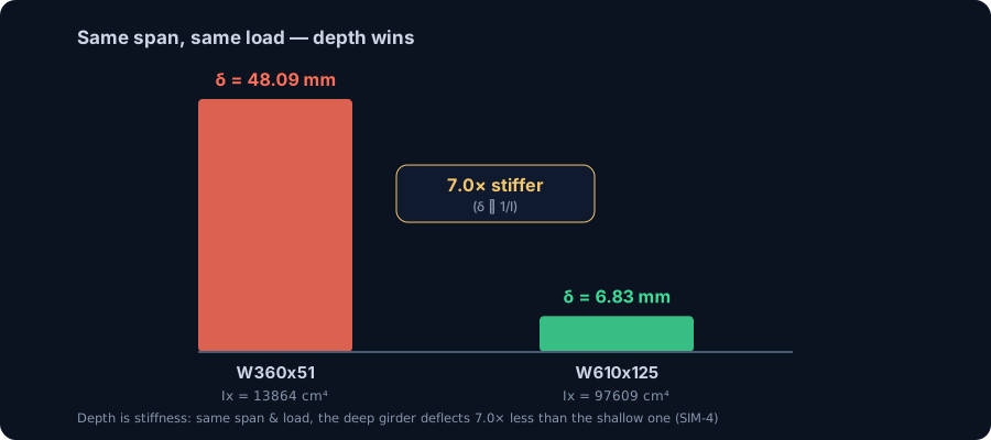
Let CalcSteel make the point in numbers. We take the same representative deck girder, the same 8 m span, and the same self-weight of 25 kN/m as in Worked Example 1, and we change only one thing: the depth of the section.
- Shallow girder — W360x51 (moment of inertia Ix = 13,864 cm&sup4;): the FEM engine returns a midspan deflection of 48.09 mm.
- Deep girder — W610x125 (Ix = 97,609 cm&sup4;): the same load, the same span, deflects only 6.83 mm.
The deep section deflects 7.0x less. That is not a coincidence and it is not the strength of the steel doing the work — both sections are the same grade of steel. It is geometry. The moment of inertia of the deep girder is 7.0x larger, and elastic deflection is inversely proportional to it: delta ∝ 1/I. Seven times the I, one-seventh the sag. Depth is the cheapest stiffness you can buy, because moving material away from the neutral axis grows I with the square of the distance.
This is exactly why Roebling did not hang a thin roadway from the cables and call it done. He wove the deck into a deep stiffening truss and fanned diagonal stay cables down from the towers. Together they give the deck the vertical and torsional rigidity that a suspension span, left to itself, does not have. The cables carry the load; the stiffening truss controls the shape — it stops local loads from drawing sharp kinks into the deck and damps the tendency of a long, flexible ribbon to move in the wind.
The bridge that skipped this lesson was the first Tacoma Narrows Bridge, which twisted itself apart in a moderate wind in 1940. Its shallow, torsionally soft plate-girder deck had plenty of strength but almost no stiffness against the aerodynamic forces feeding energy into it. Brooklyn's deep, triangulated, multiply-braced deck is the physical opposite — and 140+ years of service is the receipt. When you size a member, verify strength and serviceability; the deflection check is not a formality.
Want to see how depth and span drive deflection on your own numbers? Read our guide to deflection limits and the deeper treatment of serviceability, deflection and vibration, then push the depth slider in the beam calculator and watch delta collapse as I grows.
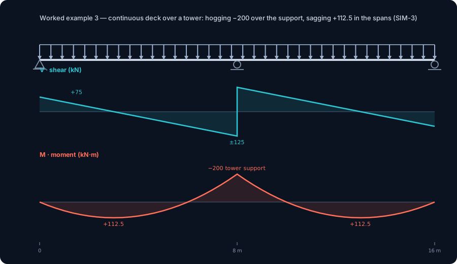
Worked example 3: continuity over the towers
So far the deck has been chopped into single, simply-supported spans — each one free to be solved with nothing more than statics. The real bridge is not built that way. The stiffening truss runs continuous across the towers, and continuity changes the mechanics in a way that is impossible to capture one span at a time. To show it, we model two 8 m spans of representative deck sharing a single interior support over the tower, still carrying the self-weight of 25 kN/m.
The moment the deck becomes continuous, it becomes statically indeterminate. There are now more unknown reactions than equilibrium equations can supply, so ΣF and ΣM alone cannot finish the job. You need a compatibility condition — the deck has to stay continuous and unbroken over the support — and that is where hand methods (moment distribution, slope-deflection) start to hurt and where a FEM engine simply solves the whole system at once. CalcSteel returns:
- Hogging moment over the tower support: -200.0 kN·m (= -wL²/8). The deck bends the other way here — tension on top, compression on the bottom — the exact reverse of a simple span.
- Sagging moment in each span: +112.5 kN·m (= 9wL²/128).
- Reactions: 75 kN at each outer support and 250 kN at the interior tower support.
Two results are worth pausing on. First, the interior support carries far more than the outer ones — 250 kN versus 75 kN — because continuity draws load toward the stiff support over the tower. That is precisely the behaviour a tower wants: it is the strong point, and continuity feeds the load to it. Second, compare the peak span moment here, +112.5 kN·m, with the +200.0 kN·m you got when the identical span was simply supported (Worked Example 1). Same steel, same load — but continuity has redistributed the demand, pulling moment out of the span and parking it as hogging over the support. The structure shares the work instead of concentrating it.
This is one of the quiet superpowers of a continuous stiffening truss: it makes the deck behave as one cooperative system rather than a row of independent beams, and it means no single midspan section has to survive the full simple-span moment. The catch is that the hogging region over the tower now needs its own attention — the top of the deck is in tension there — which is why continuous structures are detailed carefully over their supports.
The honest caveat still holds: this is a representative modern-steel model of how a continuous deck behaves as a beam, not a reconstruction of the 1883 members. But the behaviour — indeterminacy, redistribution, load drawn to the towers — is exactly the behaviour Emily and Washington Roebling had to reason about with pencil, paper and the mathematics she mastered. The FEM engine just does in milliseconds what took them months.
Roebling's factor of six — and the wire fraud that ate it
Every number so far has been a demand — how hard the load pushes on the deck. The other half of engineering is capacity — how hard the section can push back before it yields. The gap between them, expressed as a ratio, is the factor of safety, and it is the whole reason a bridge from 1883 is still open.
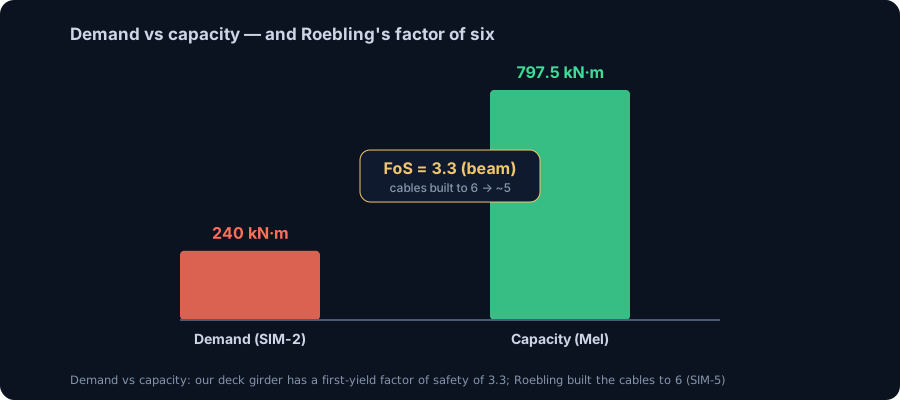
Take our deep deck girder, the W610x125. Its elastic section modulus is Sx = 3,190 cm³, and at a yield strength of fy = 250 MPa the first-yield moment capacity is:
- Mel = Sx · fy = 797.5 kN·m — the moment at which the outermost fibre first reaches yield.
Now set that against the worst demand we found — the moving concentrated load of Worked Example 2, 240 kN·m:
- Utilization = 240 / 797.5 = 0.30. The section is working at 30% of its first-yield capacity.
- Factor of safety on first yield = 797.5 / 240 = 3.32. The deck could take 3.3x its governing moment before the steel even begins to yield — and yielding is still a long way from collapse.
That is a comfortable, deliberate margin. It exists not because the engineer expects the design load, but because of everything the engineer cannot fully predict: overload, impact, corrosion over a century, fabrication scatter, and — as Brooklyn learned — outright fraud. If you want the reasoning behind numbers like this, see how factors of safety work and the role of the section modulus in turning a shape into a moment capacity.
Roebling took the same philosophy much further on the parts that could not fail. He designed the four main cables to a factor of safety of six — six times stronger than the calculated requirement. That enormous margin turned out to be the bridge's salvation. During construction the wire contractor, J. Lloyd Haigh, committed wire fraud: he ran inspected, approved wire past the inspectors and then diverted it, delivering rejected, inferior wire to the site instead. By the time the swap was discovered in 1878, the bad wire was already spun into the cables and could not be removed.
Because the design started at six, there was room to absorb the damage. Roebling compensated by adding 150 extra wires to each cable — at Haigh's expense — and the effective factor of safety settled at about five. Still generously safe. The bridge that was cheated by its own contractor has now stood for 140+ years, and the margin Roebling insisted on is the reason a criminal act became a footnote rather than a catastrophe.
Keep the two safety factors distinct: 3.32 is our worked figure for a representative deck girder in bending, computed live in CalcSteel; six-falling-to-five is the historical figure for Roebling's main cables in tension. Different members, different jobs — but the same idea, that the margin is there for the unknowns, and the unknowns are real.
Modeling a steel structure in CalcSteel
Every number in this article came out of the same place: CalcSteel's real FEM engine — the shipping app.engine.solver that assembles the stiffness matrix, applies your loads, and solves for displacements and internal forces. It is not a lookup table or a hand-formula wrapper. It is a genuine finite-element solver, and each determinate result you have seen (reactions, shear, moment, deflection) was validated against closed-form theory to three decimals before we published it.
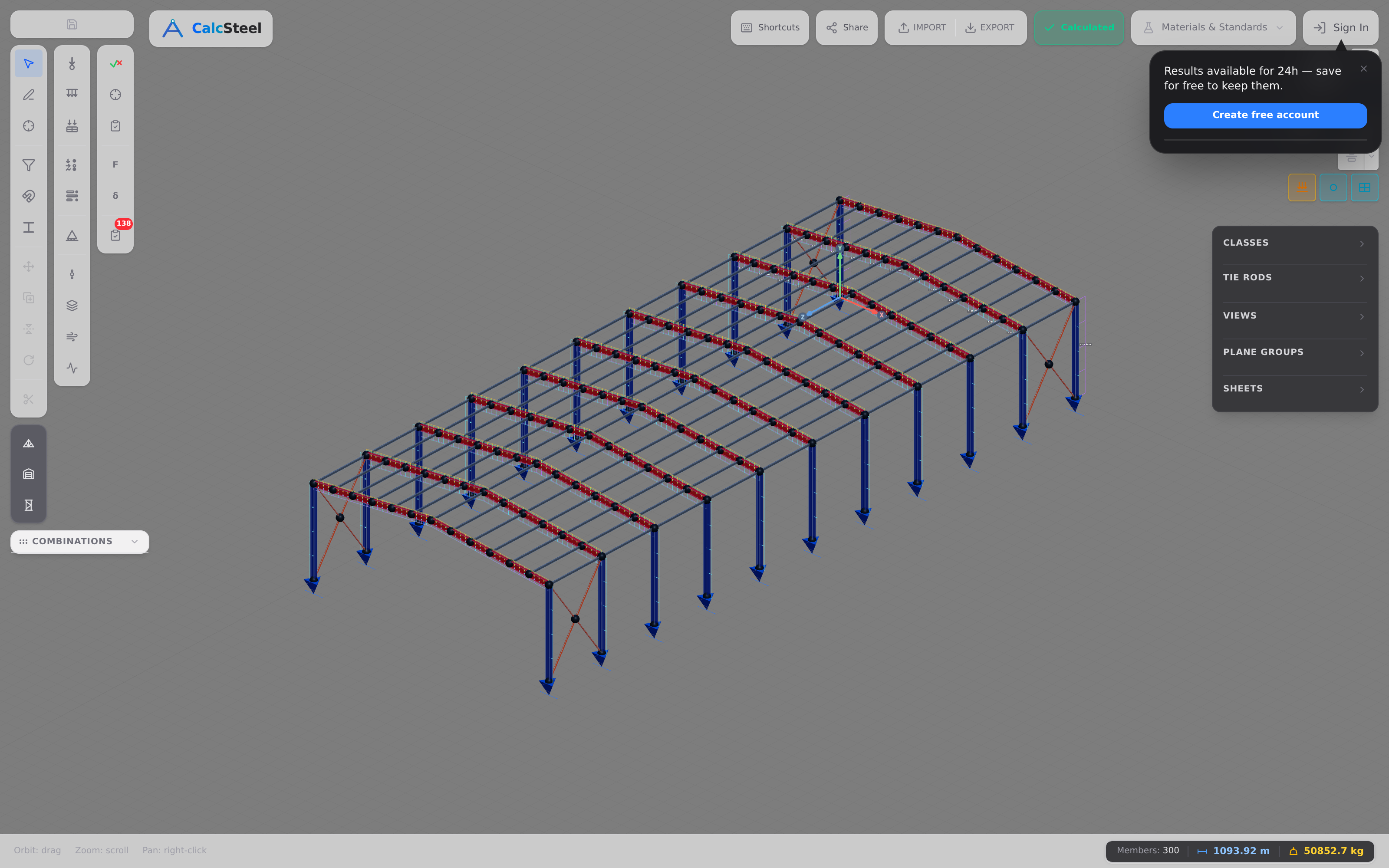
Here is the honest caveat first: the screenshot below is a representative modern steel frame, not the 1883 Brooklyn Bridge itself. We are not claiming to have modeled Roebling's exact wrought-iron and steel-wire members. What we are showing is the workflow — the same engine, the same diagrams, the same verification logic that let us reproduce how the deck and stiffening truss behave as a beam.
The workflow is short and it is the same one you would use for a warehouse portal, a mezzanine, or a footbridge:
- Build the geometry. Drop nodes, connect members, and assign a profile. For our deck examples that profile was a W610x125 deep girder, grade fy = 250 MPa, E = 200 GPa.
- Apply supports and loads. Pin and roller supports for a simply-supported span; a uniform line load w for self-weight; a concentrated P for a crossing load; a continuous line over two spans for the tower-continuity case.
- Run the FEM engine. The solver returns reactions, the shear diagram, and the bending-moment diagram — the very Mz diagram you have been reading, with the sagging +200 kN·m, +240 kN·m, and the hogging −200 kN·m over an interior support.
- Read the code-check colors. CalcSteel verifies each member and paints it by utilization. Our deck girder ran at a utilization of 0.30 against first yield — comfortably green — because demand (240 kN·m) sits far below the 797.5 kN·m first-yield capacity.
That is the whole loop: model, solve, verify, iterate. The bridge examples are a case study, but the engine is a general-purpose tool. You can open CalcSteel in your browser and build a steel structure of your own — the math runs free, right where you are, with no desktop install.
Engineering lessons + common mistakes
Strip away the granite towers and the neo-Gothic arches and the Brooklyn Bridge is a lesson in a handful of principles that still govern every structure you will design. Here is the checklist, each one tied back to something we either computed or verified.
- Redundancy buys robustness. The bridge carries load through three independent paths — the main catenary cables with their suspenders, the diagonal stays fanning from the towers, and the deck-level stiffening truss. When Haigh's fraudulent wire turned out to be un-removable, that redundancy is part of why the structure still had margin. Design load paths, not lucky single members.
- Stiffness is not strength. A member can be strong enough to never yield and still be unacceptably flexible. Our shallow W360x51 and deep W610x125 had the same job, but the shallow one deflected 48.09 mm versus 6.83 mm — 7.0× more — because deflection scales with 1/I, not with strength. Tacoma Narrows (1940) had strength and lacked stiffness. Roebling's deep truss and diagonal stays gave the vertical and torsional stiffness that kept Brooklyn steady.
- Moving concentrated loads govern. The deck's own weight produced 200 kN·m. A single 120 kN load crossing at midspan produced 240 kN·m — a 20% higher peak from a load that is far lighter in total. This is why bridges are designed for moving vehicles, not just dead weight, and why the stiffening truss exists to spread those point loads out.
- Continuity redistributes moment. Make the deck continuous over a tower and the peak sagging moment drops from 200 to +112.5 kN·m, at the cost of a hogging −200 kN·m over the support. The structure is now statically indeterminate — hand methods get painful, and a FEM engine solves it instantly.
- Factors of safety exist for the unknowns. Roebling designed the cables to a factor of six. Wire fraud ate part of it, dropping the margin to about five — and the bridge stood, because that margin was there precisely for the things nobody plans: fraud, corrosion, overload, the load you did not imagine. Never design to exactly 1.0.
- Model the whole load path, not one member. A perfect floor-beam bolted into a weak connection into an overstressed cable is a failed bridge. Verify the chain.
Frequently asked questions
Is the Brooklyn Bridge a suspension or a cable-stayed bridge? Both — it is a hybrid. Its primary system is suspension (main catenary cables with vertical suspenders hanging the deck), but Roebling added diagonal stay cables fanning down from the towers, which is a cable-stayed element. Those stays were later judged not strictly necessary, but they were kept for the extra stiffness and the iconic look. The deck-level stiffening truss completes the trio.
Why hasn't the Brooklyn Bridge collapsed? Three reasons compound: a high original factor of safety (six on the cables), three redundant load paths so no single element is fatal, and a stiff deck truss that resists the wind-driven oscillation that destroyed Tacoma Narrows. Even after the wire fraud dropped the cable margin to about five, and after 140+ years of traffic, it remains safe — though it has been reinforced and maintained continuously.
What steel is the Brooklyn Bridge made of? It was the first suspension bridge to use steel wire for its main cables — earlier suspension bridges used iron. Its four main cables, each about 0.4 m (15.75 in) in diameter, each bundle more than 5,000 galvanized steel wires. The towers themselves are masonry (limestone and granite), not steel.
Key takeaways
The Brooklyn Bridge was finished from the plans of a man already dead, under a chief engineer too ill to leave his bed, with Emily Warren Roebling directing the works for over a decade — and 140+ years later it still carries traffic. The engineering that makes that possible is the same engineering you can compute today.
- It is a hybrid of three systems. Suspension cables, diagonal stays, and a deck stiffening truss give three redundant load paths — the root of its famous robustness. It was the world's longest suspension bridge at completion in 1883, main span 486.3 m, and the first with steel-wire cables.
- The deck behaves as a beam. Under self-weight our representative girder saw +200 kN·m (wL²/8) and deflected 6.83 mm; a 120 kN crossing load pushed the peak to +240 kN·m (PL/4). Moving concentrated loads govern.
- Depth equals stiffness. A deep W610x125 deflected 7.0× less than a shallow W360x51 under identical load, tracking its 7.0× larger moment of inertia. Roebling's deep truss is what keeps the deck rigid.
- Continuity and indeterminacy need FEM. A two-span continuous deck gives −200 kN·m of hogging over the tower and +112.5 kN·m in the spans — solvable by hand, but instant with a real solver.
- Safety factors are for the unknowns. Our deck girder ran at utilization 0.30 (FoS 3.32 on first yield); Roebling's cables were designed to six, and survived wire fraud down to about five. The margin is the point.
Now build it yourself. Open the free beam calculator and drive the shear, moment, and deflection in real time — no login for the math. When you want the full FEM workflow with member verification, CalcSteel is genuinely free to start in your browser (never a countdown trial — a real free plan, plus live calculators). And if you are a student, our education offer is free — bring the engineering behind the world's most famous bridge into your own projects.
Sources
Try CalcSteel for free
Model, analyze and design steel structures in your browser. No install, no signup.
Open the 3D editor