Section Modulus (Sx, Zx): Formula & Meaning
Two small letters decide how much bending a steel beam can carry: S for elastic section modulus and Z for plastic. Both convert the geometry of a cross-section into a single number that, multiplied by the steel's yield stress, gives the bending moment the section can resist. Bending strength is only one of several limit states an engineer must check, but it is the one these two numbers govern. This deep-dive traces where they come from, the plastic-design revolution that gave us Z, a worked example end-to-end, and how a browser tool resolves them in milliseconds. It also turns the beam on its side to read the weak-axis modulus, where the shape factor climbs toward 1.5, and visits the singly-symmetric sections whose plastic neutral axis leaves the centroid.
Key takeaways
- The elastic modulus is S = I / c (moment of inertia over distance to the extreme fiber); the plastic modulus Z sums the first moments of the two half-areas about the plastic (equal-area) neutral axis.
- Their ratio is the shape factor Z/S = Mp/My; for a rectangle it is exactly 1.5, while real wide-flange I-shapes fall in roughly 1.10-1.18 (about 1.12 is typical).
- Notation is regional: North America uses S and Z, while Eurocode 3 writes Wel and Wpl for the same quantities.
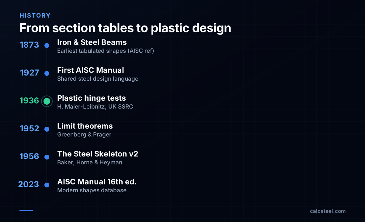
- Tabulated section properties trace back over a century - AISC shape data reaches back to Iron and Steel Beams 1873 to 1952 and the first AISC Manual of 1927.
- The numbers are axis-dependent: bent the weak way a wide-flange has a shape factor near 1.5 (vs about 1.13 the strong way), and for a singly-symmetric section (a tee, an unequal-flange girder) the plastic neutral axis is the equal-area line, which does not coincide with the elastic centroid.
S and Z: one number that sets bending capacity
The section modulus is a purely geometric property of a cross-section that converts a bending moment into a bending stress. The elastic section modulus is defined as S = I / c, where I is the second moment of area about the bending axis and c is the distance from the neutral axis to the extreme fiber. Multiply it by the yield stress and you get the moment at which the outermost fiber first reaches yield: My = S · σy.
The plastic section modulus describes what happens after that. As a ductile steel section yields progressively until the entire cross-section has gone plastic, its capacity is Mp = Z · σy, where Z = A_C·y_C + A_T·y_T — the compression and tension areas each multiplied by the distance from their own centroid to the plastic neutral axis. That axis is the equal-area axis: the line that splits the cross-section into two equal areas (which, for a doubly-symmetric shape, coincides with the elastic centroidal axis). Z is meaningful only for materials ductile enough to redistribute stress, and unlike S it has no fixed relationship to the moment of inertia.
The shape factor: why Z beats S
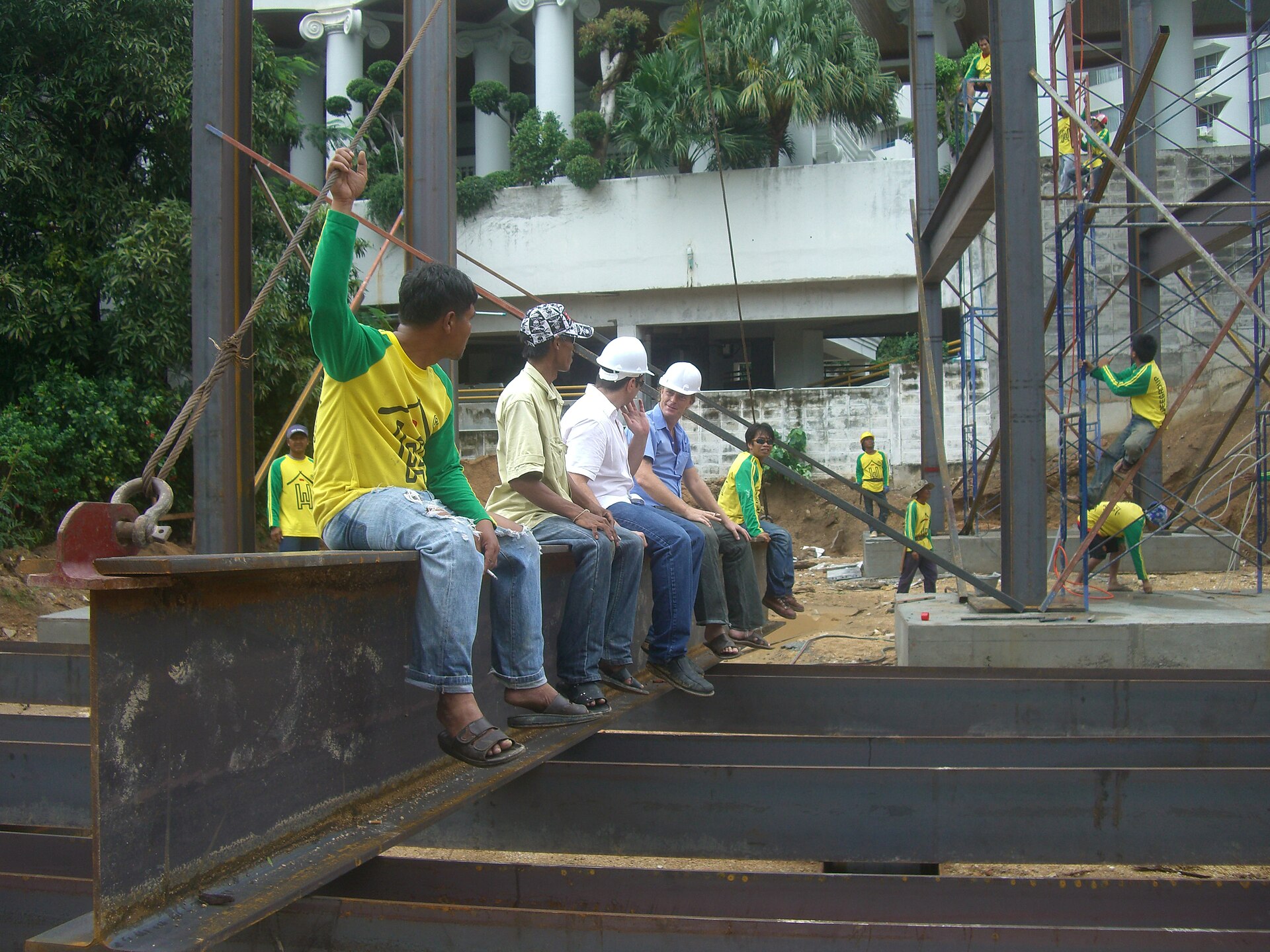
Because S is governed by the most distant fiber while Z weighs the whole area at its lever arm, Z ≥ S always; for the doubly-symmetric sections shown here, Z is strictly larger than S. Their ratio is the shape factor:
- k = Mp / My = Z / S — the reserve strength between first yield and full plastic capacity.
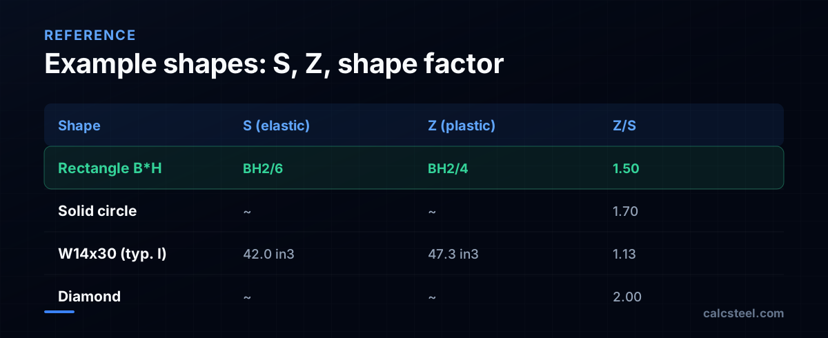
- A rectangle has S = BH²/6 and Z = BH²/4, so k = 1.5 exactly — a 50% bonus.
- A typical I-beam falls in the range 1.10-1.18 (about 1.12 is typical), because most of its material sits in the outer flanges, far from the neutral axis, where elastic and plastic stress states nearly coincide.
That difference is not academic. Designing to Z instead of S unlocks the plastic reserve that elastic-only methods leave on the table — and it is why the plastic modulus became the backbone of modern limit-state steel design.
A worked example: W14x30 from S to moment capacity
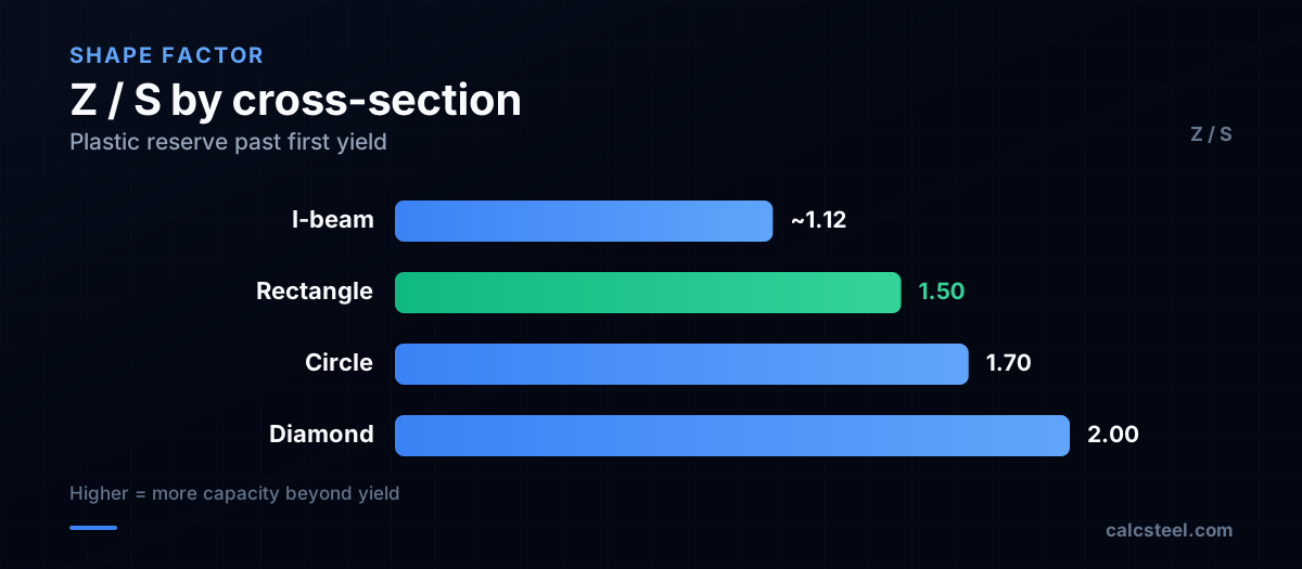
Numbers make it concrete. Take a W14x30 wide-flange section. From the AISC Shapes Database its published properties are depth d = 13.84 in, moment of inertia Ix = 291 in⁴, and plastic modulus Zx = 47.3 in³.
- Distance to extreme fiber: c = d/2 = 13.84 / 2 = 6.92 in.
- Elastic modulus: Sx = Ix / c = 291 / 6.92 = 42.0 in³ (matching the tabulated value).
- Shape factor: Zx / Sx = 47.3 / 42.0 = 1.13 — squarely inside the I-shape range.
Now apply A992 steel with yield stress Fy = 50 ksi. First yield arrives at My = Sx · Fy = 42.0 × 50 = 2100 kip·in = 175 kip·ft (≈ 237 kN·m). The full plastic moment is Mp = Zx · Fy = 47.3 × 50 = 2365 kip·in = 197 kip·ft (≈ 267 kN·m). The 13% jump from My to Mp is exactly the plastic reserve that elastic design discards — and the reason limit-state codes let compact sections — when adequately braced against lateral-torsional buckling — be checked against Mp.
The weak axis tells a different story: Sy and Zy
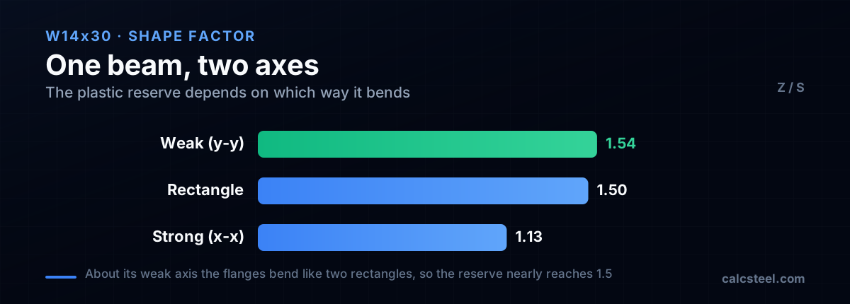
Everything so far bent the W14x30 about its strong axis (x-x), the one the beam's depth serves. Stand the same section on its side and bend it about the weak axis (y-y) and the numbers shift. From the AISC Shapes Database its minor-axis properties are Iy = 19.6 in⁴, Sy = 5.82 in³ and Zy = 8.99 in³, and the elastic value follows straight from geometry: c = bf/2 = 6.73/2 = 3.37 in, so Sy = Iy/c = 19.6/3.37 = 5.82 in³.
The revealing number is the shape factor: Zy/Sy = 8.99/5.82 = 1.54. About the strong axis this very section gave only 1.13; about the weak axis it climbs past even the rectangle's 1.50. The cause is geometric. Bending about y-y, each flange acts like a stocky rectangle bending about its own strong direction, with material spread evenly from the axis out to the tips instead of concentrated in two thin extreme fibers. So the plastic reserve is far larger than most engineers carry in their heads: for minor-axis bending (AISC 360 Section F6) and biaxial checks (AISC 360 Chapter H, Eurocode 3 clause 6.2.9), the jump from first yield to full plastification is about 54%, more than four times the 13% on the strong axis. It is also why a doubly-symmetric I-shape bent the weak way is never governed by lateral-torsional buckling: there is no weaker axis left to buckle toward.
When the plastic neutral axis leaves the centroid
For every doubly-symmetric shape so far, S and Z shared a single line: the plastic neutral axis (the equal-area line) sat exactly on the elastic centroid. That coincidence is a special case. For a singly-symmetric section (a tee, a channel bent about its horizontal axis, or a plate girder with unequal flanges) the two axes separate, and Z can no longer be read from the same line as S.
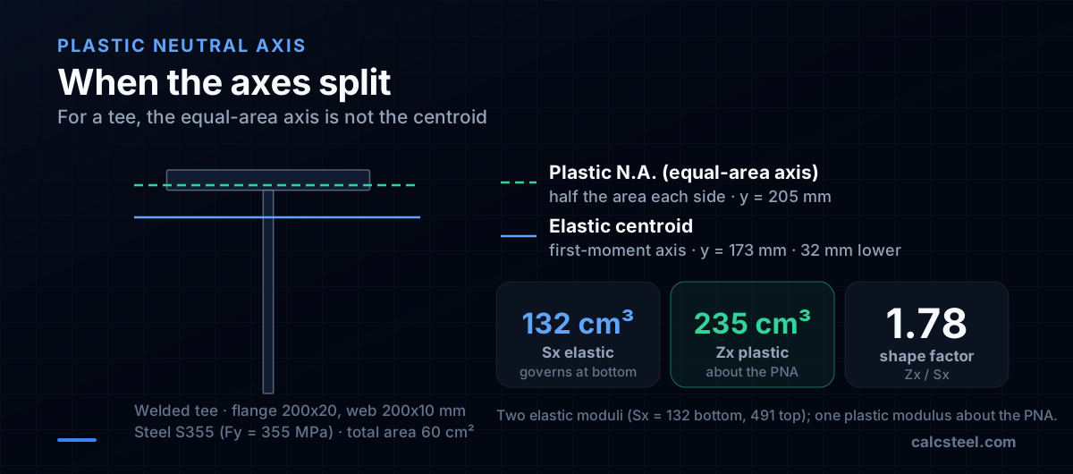
Take a welded tee: a 200 x 20 mm flange on a 200 x 10 mm web, 6000 mm² in all. The elastic centroid is the first-moment axis: y = (2000·100 + 4000·210)/6000 = 173 mm above the web tip. The plastic neutral axis is the equal-area axis, splitting the 6000 mm² into two halves of 3000 mm². Because the flange alone is 4000 mm², that line lands inside the flange, at 205 mm, a full 32 mm above the elastic centroid.
The consequences are practical. Being asymmetric top-to-bottom, the tee has two elastic moduli, not one: Sx = Ix/c works out to 132 cm³ at the far (bottom) fiber and 491 cm³ at the near (top) fiber, and design takes the smaller, because that fiber reaches yield first. The plastic modulus is single, measured about the PNA: Zx = sum of A·y about the equal-area line = 235 cm³. The shape factor is therefore Zx/Sx = 235/132 = 1.78, far above any I-beam, because first yield at the distant fiber arrives early while full plastification still mobilizes the whole area. The rule that follows: for anything but a doubly-symmetric shape, locate the equal-area axis first, then sum first moments about it. Reading S and Z off the same line is the mistake singly-symmetric sections punish.
The plastic-design revolution
For most of the 19th and early 20th centuries, beams were sized with the elastic modulus S alone — capacity stopped, by assumption, at first yield. The shift gathered force in 1936, when the British Steel Structures Research Committee's effort to build a rational elastic method led engineers straight into the plastic range. Around that period German engineer Hermann Maier-Leibnitz (1885-1962) ran the pivotal tests on continuous steel beams that demonstrated plastic hinges forming where a section fully yields, and showed the ultimate load was insensitive to support settlement. (Sources occasionally confuse him with the nuclear physicist Heinz Maier-Leibnitz, born 1911; the structural-engineering work is Hermann's, as documented in Kurrer's biography.)
J. F. Baker later repeated and extended this work at Bristol, after meeting the central-European researchers at the 1936 IABSE congress. Research at Bristol and Cambridge through the late 1940s and early 1950s — including work by M. R. Horne and the limit theorems of Greenberg and Prager (1952) — gave plasticity a rigorous foundation. The capstone was The Steel Skeleton, Volume 2: Plastic Behaviour and Design by J. F. Baker, M. R. Horne and J. Heyman (Cambridge University Press, 1956; ISBN 0521040884), which became the canonical text. From there, Z moved from the laboratory into design codes worldwide.
S/Z vs Wel/Wpl: the same idea, two dialects
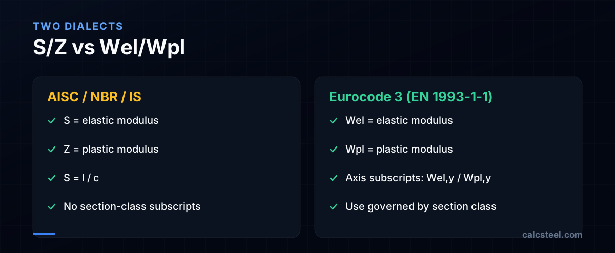
The single biggest source of confusion is notation, not physics. North American practice (AISC 360) writes S for elastic and Z for plastic. Eurocode 3 (EN 1993-1-1) writes Wel and Wpl, with axis subscripts — Wel,y and Wpl,y about the major axis, Wel,z and Wpl,z about the minor.
Which one a code lets you use depends on cross-section class. In Eurocode 3, compact Class 1 and 2 sections — those that can reach and rotate at full plasticity without local buckling — are checked with Wpl; slender Class 3 sections fall back to Wel. The second-generation EN 1993-1-1:2022 (the new prEN/2022 revision now rolling out across Europe) adds an elasto-plastic modulus Wep for Class 3, with determination rules in Annex B that interpolate between the elastic and plastic resistances. The lesson for anyone working across NBR 8800, AISC 360, Eurocode 3 and IS 800: the quantity is identical, but the symbol, the axis convention and the eligibility rules are not.
Where the numbers in the tables come from
Engineers rarely compute S and Z from scratch — they read them from section tables, the accumulated output of more than a century of standardization. AISC's historic shape data reaches back to the reference volume Iron and Steel Beams 1873 to 1952 (an AISC compilation of pre-1953 rolled shapes), and the first AISC Steel Construction Manual appeared in 1927, consolidating dimensions, properties and design aids into a shared language for the trade. The Manual is now in its 16th edition (2023).
Naming follows that same standardized logic. A W14x30 is a wide-flange shape nominally 14 inches deep weighing 30 lb per foot — though "nominal" is approximate (a W14x30 is actually 13.84 in deep). Modern AISC Shapes Database releases encode every property under the EDI naming convention so software can ingest them directly. Europe runs a parallel system — IPE, HEA, HEB, UB, UC — with properties published the same way.
From hand tables to the browser
Computing S by hand means finding the centroid, integrating for I, then dividing by c. Z demands locating the plastic neutral axis (the equal-area axis) and summing first moments of each half. Doable — as the W14x30 example above shows — but error-prone and tedious to repeat for every member in a frame, under every load combination and code convention.
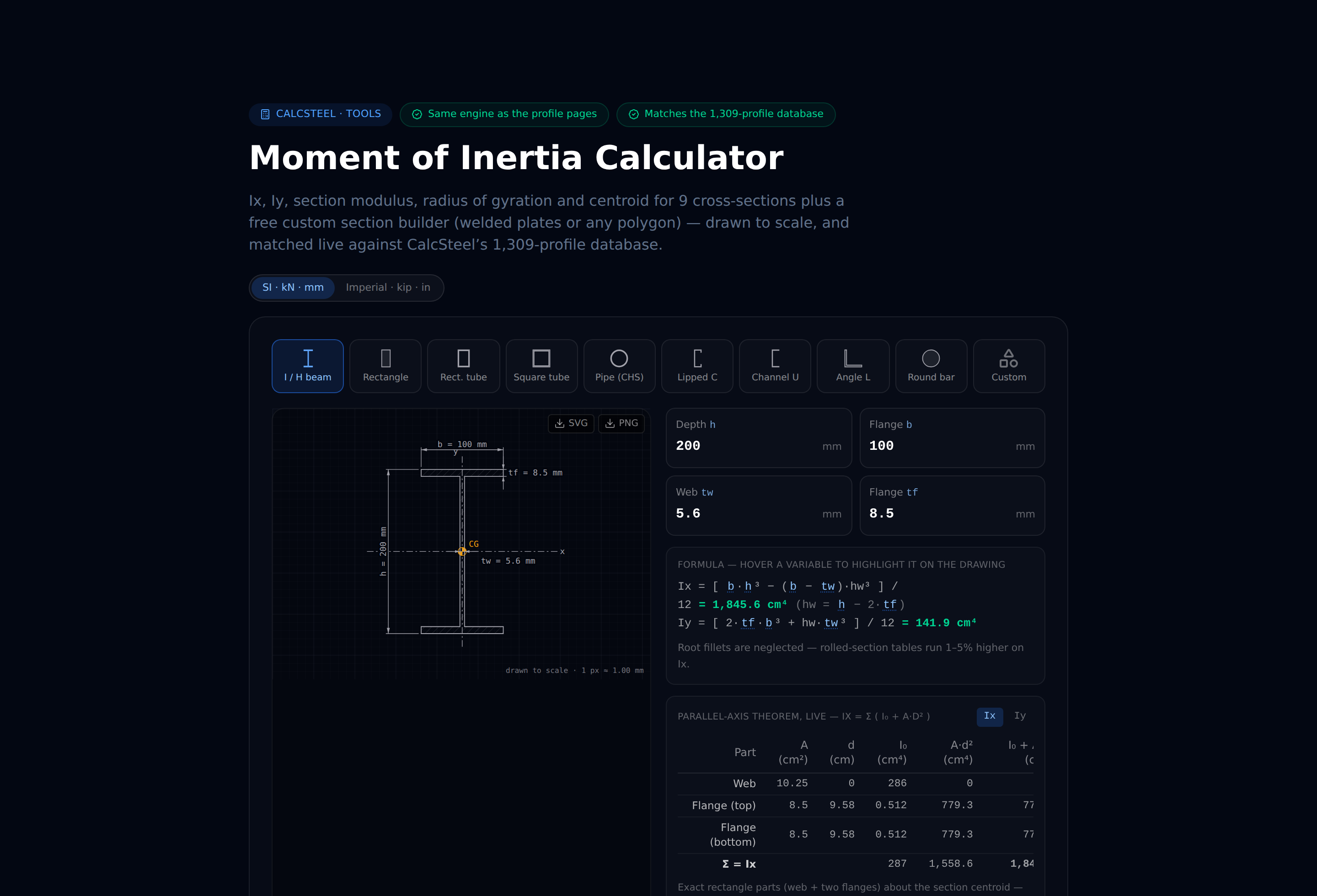
That repetition is what software removes, and several tools do it. Spreadsheet add-ins and viewers (for example the steeltools.org AISC properties viewer) tabulate S and Z; full design suites such as SkyCiv, Dlubal and SCIA carry the section libraries plus code checks. CalcSteel is one option in that field — a browser-native tool (React/TypeScript front end, Python finite-element backend) with 1,140+ steel profiles whose section properties (S, Z, I and more) are resolved instantly and fed straight into code checks for NBR 8800, AISC 360, Eurocode 3 and IS 800, so the right modulus is applied under the right convention automatically. It offers a free plan with the full editor, plus paid Starter and Pro plans, monthly or annual, with prices for your country on the pricing page. Section modulus is also the pivot of sizing a steel beam, and bending strength is only one of the checks that decide a member. For a quick lookup, a free section-properties calculator (no sign-up) returns I, S and Z for a shape right in the browser. Understanding S and Z is still essential engineering literacy — but once you do, you can let the editor handle the arithmetic and spend your judgment on the design.
Sources
- 1.Section modulus - Wikipedia
- 2.Plastic design in structural steel (Lehigh / CORE) - history of plastic theory
- 3.Kurrer: Hermann Maier-Leibnitz (1885-1962), pioneer of structural steel - Stahlbau / Wiley Online Library
- 4.The Steel Skeleton, Vol. 2: Plastic Behaviour and Design (Baker, Horne, Heyman, CUP 1956) - ISBN 9780521040884
- 5.Iron and Steel Beams 1873 to 1952 - AISC historic shapes reference (HathiTrust catalog record)
- 6.AISC Shapes Database v16.0 - Steel Construction Manual
- 7.AISC EDI Naming Convention for Structural Steel Products (PDF)
- 8.EN 1993-1-1 Eurocode 3: Design of Steel Structures (Wel/Wpl, section classes) - EU Eurocodes / JRC
- 9.Jonathan Ochshorn - Strength of materials: elastic and plastic section modulus
- 10.Image: Designer Mario Kleff — CC BY-SA 4.0 (Wikimedia Commons)
Try CalcSteel for free
Model, analyze and design steel structures in your browser. No install, no signup.
Open the 3D editor