AI in Structural Engineering: What It Can and Can't Do
AI in structural engineering for engineers: what LLMs, generative design and ML really do, why mechanics still governs, and how to verify every number. Free beam calculator inside.
Key takeaways
- AI (LLMs, ML surrogates, generative design, computer vision, automation) accelerates the workflow — but every layer sits on a deterministic mechanics core it cannot replace.
- LLMs predict plausible text, not correct forces: our IPE 330 beam (L=6 m, w=25 kN/m) is trustworthy only because a real FEM engine reproduces R=75 kN, Mmax=112.5 kN·m and δ=L/322 to the decimal.
- 'Generative design' is constrained optimisation: for that beam, strength passes for every rolled section — deflection governs. The honest minimum is an IPE 330; playing safe with an IPE 500 wastes 46% of the steel.
- Only FEM solves the real indeterminate frame: our portal redistributes the beam moment from 252 to 213 kN·m, and 213.1 + 38.9 (average knee) = 252 = wL²/8 exactly — an LLM can only guess it.
- AI proposes, mechanics disposes: the engineer of record — not the model — verifies, stamps and owns every number. Check any AI's beam in the free calculator.
AI in structural engineering — the promise, and the physics it can't skip
An AI can now draft a design report, look up a code clause, sketch a structural layout and suggest a steel section in seconds — faster than any engineer alive. It can also state, with total confidence, that a beam is safe when it is not. Both of those are true at the same time, and holding them together is the whole job of AI in structural engineering.
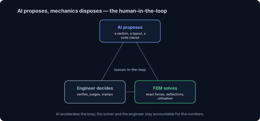
The reconciliation is simple to say and hard to practise: AI proposes, mechanics disposes. A large language model predicts plausible text; a real structure obeys equilibrium, stiffness and a code check that do not care how confident the model sounded. So the useful question is never "can AI do structural engineering?" — it is "where does AI genuinely help, and what must still be computed and verified deterministically?"
This is the engineer's guide to exactly that line. Every structural number below comes from a real FEM engine — reactions, shear, moment, deflection, whole-frame redistribution — and each is the kind of ground truth an AI's guess has to survive. There is a live beam calculator embedded further down, so you can check any AI's answer yourself.
We wrote it for three readers:
- Engineering students — see what AI actually is under the marketing, and why the mechanics you are learning is the part that never gets automated away.
- Practising engineers — where LLMs, ML and generative design pay off today, where they fail, and how to keep verification (and liability) firmly in your hands.
- Firm leaders and the tech-curious — a grounded read on what to adopt now versus what is still hype.
What 'AI in structural engineering' actually means
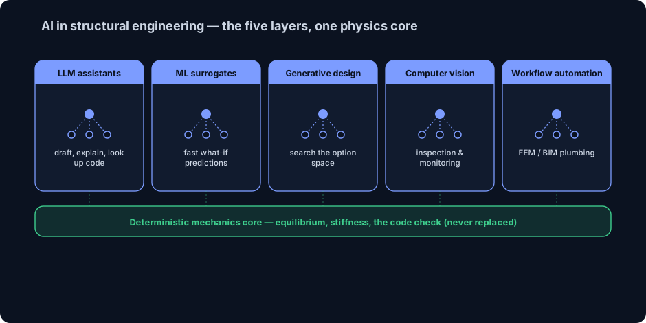
AI in structural engineering is the use of machine-learning and language-model systems — LLM assistants, ML surrogate models, generative/optimisation design, computer vision and workflow automation — to speed up structural design, analysis and inspection. These tools accelerate the work around the physics; they do not replace the deterministic mechanics — equilibrium, the stiffness method and the code check — that decides whether a structure is safe.
Strip away the marketing and today's "AI" in this field is five distinct layers, each doing a different job:
- LLM assistants — drafting text, explaining concepts, looking up and summarising code provisions, writing analysis scripts. Superb at language; unreliable at arithmetic and at any specific engineering number.
- ML surrogate models — fast approximators trained on thousands of solved cases to predict a result (a natural frequency, a utilisation, a wind pressure) in milliseconds instead of a full analysis.
- Generative / optimisation design — algorithms that search a space of geometries or member sizes against constraints, proposing candidate structures for the engineer to judge.
- Computer vision — detecting cracks, corrosion and defects in images, and structural-health-monitoring (SHM) from sensor data.
- Workflow automation — extracting data from drawings and specs, connecting BIM and FEM, and removing the manual plumbing between tools.
The single most important thing to see is what sits underneath all five: a deterministic mechanics core. Every one of these tools is only trustworthy to the extent its output is checked against equilibrium and a real analysis. AI is the fast, fallible layer on top; the physics is the foundation that never moves.
From the stiffness matrix to the neural net: a short history
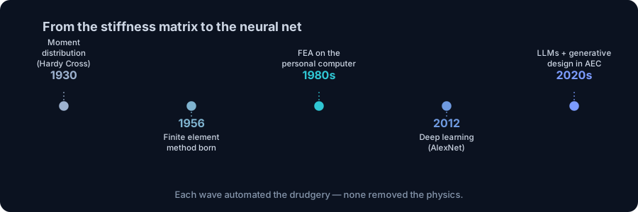
"Computers doing structural analysis" is not new — automating it has been the story of the field for nearly a century, and every wave automated more drudgery without ever removing the mechanics.
- 1930 — moment distribution (Hardy Cross). A hand method to solve indeterminate frames by iteration. The first time redistribution became routine — done with paper, not silicon.
- 1956 — the finite element method is born. Turner, Clough, Martin and Topp publish the direct-stiffness formulation for complex structures. This is the deterministic engine that still runs inside every modern analysis package — including the one used for the numbers in this article.
- 1980s — FEA reaches the desktop. The personal computer puts matrix analysis on the engineer's own machine. (This decade also saw the first "AI" wave — rule-based expert systems — quietly fail and trigger an "AI winter": a useful reminder that confident automation is not the same as correct automation.)
- 2012 — deep learning breaks through. A deep neural network (AlexNet) wins ImageNet by a wide margin, and modern machine learning takes off — the technology now behind defect-detection and SHM.
- 2017 → 2020s — transformers and LLMs. The transformer architecture ("Attention Is All You Need") leads to the large language models and generative-design tools now arriving in AEC.
The through-line is unmistakable: each advance automated the labour — the arithmetic, the lookup, the drafting — and none of them removed the physics. The 1956 stiffness matrix is still doing the real work; the neural net is a new layer on top of it, not a replacement for it.
Where AI genuinely helps today
Scepticism about AI numbers should not tip into dismissing AI. Used with judgement, it already earns its place in the workflow:
- Drafting and documentation. First drafts of reports, method statements, specifications and emails — the engineer edits, the AI removes the blank page.
- Code and standard lookup. Finding and explaining the relevant clause of NBR 8800, AISC 360 or EN 1993 far faster than flipping pages — then you confirm it against the actual standard.
- Parametric and generative exploration. Sweeping dozens of layouts, spans or member sizes to surface options a human might not try — a shortlist to evaluate, not a design to trust blindly.
- ML surrogates for fast what-if. Near-instant estimates during early design, when you want direction, not a final check.
- Computer vision for inspection and SHM. Flagging cracks and corrosion in thousands of images, or watching sensor data for anomalies — tireless triage that focuses the engineer's attention.
- Data extraction and BIM/FEM plumbing. Pulling quantities from drawings, reconciling models, automating the tedious hand-offs between tools.
Notice the pattern in every win: AI proposes, drafts, flags and accelerates — and a human plus a deterministic tool verifies and decides. That is the discipline the rest of this guide makes concrete: keep AI in the loop, but keep the solver and the engineer accountable for the numbers.
Worked example 1: can an LLM size this beam?
Here is the most common way an engineer meets AI today: you type a request into a chatbot. "Size a simply supported steel beam, 6 m span, carrying a uniform load of 25 kN/m." A capable LLM will answer fluently — it may quote wL²/8, propose a section, even cite a capacity. Some of that will be right. Some may be silently wrong: a hallucinated section modulus, a mis-remembered limit, a check it skipped. The text gives you no way to tell which.
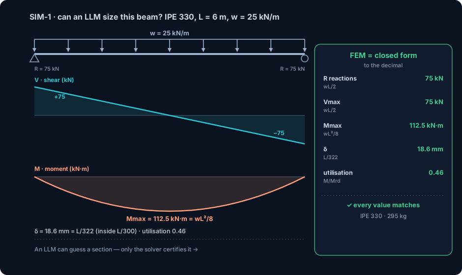
So we do what the LLM cannot: we compute it deterministically. Take the answer to that prompt — a simply supported IPE 330 in S355, span L = 6.0 m, uniform load w = 25 kN/m — and run it through the CalcSteel FEM engine. It reproduces the closed form exactly:
- End reactions: R = wL/2 = 75 kN at each support.
- Peak shear: Vmax = 75 kN at the supports.
- Peak moment: Mmax = wL²/8 = 112.5 kN·m at midspan.
- Deflection: the engine reports 18.6 mm = L/322 — inside the usual L/300 limit. (It includes shear deformation, so it sits just above the textbook 5wL⁴/384EI value of ~17.75 mm = L/338 — a real, small difference the hand formula misses.)
- Strength utilisation: against the section's elastic bending capacity MRd,el ≈ 243.5 kN·m, the utilisation is 0.46.
Every one of these numbers matched the closed-form solution to the decimal. That is the point — not that the beam is safe (it is), but that its safety is established by a deterministic computation, not by an eloquent paragraph. An LLM can guess the section; only the solver certifies it. The moment you have a number you can check, the AI stops being a black box and becomes a fast first draft. So check it — which is exactly what the calculator below is for.
Verify it yourself: the live beam calculator
Do not take the last section on faith — reproduce it. The calculator below is the real CalcSteel beam solver, embedded right here: enter a simply supported span of 6 m, a uniform load of 25 kN/m and an IPE 330, and watch it return the same 75 kN reactions, 112.5 kN·m peak moment and the deflection and utilisation from Example 1 — with full shear and bending diagrams.
This is the habit that makes AI safe to use: whenever a model hands you a beam, a load or a section, drop it in here and see the real numbers. The math is unlimited, free, and needs no login. For the theory behind what you are checking, see shear force and bending moment diagrams and how to size a steel beam; for the serviceability side, deflection limits.
Max moment
45 kN·m
Max shear
30 kN
Max deflection
10.55 mm
= L/569
Bending stress σ
84.4 MPa
σ = M/Sx
Utilization
44.0%
NBR 8800 · δ ≤ L/250
Geometry & supports
Section
Ix 7999 cm⁴ · Sx 533 cm³ · 42.2 kg/m
Point loads (↓ positive)
None — add as many as you need.
Distributed loads (uniform or trapezoidal)
Model sketch
Diagrams — free PNG / SVG / CSV export, no watermark
Step-by-step — the calculation memory of YOUR beam
IPE 300 · L = 6 m · fy = 250 MPa
1. Reactions (equilibrium of the solved FEM model)
ΣFy = 0 · ΣM = 0
R_A = 30 kN · R_B = 30 kN
2. Peak shear (read from the SFD)
Vmax = |V(x)|max
Vmax = -30 kN @ x = 6 m
3. Peak moment (read from the BMD)
Mmax = |M(x)|max
Mmax = 45 kN·m @ x = 3 m
4. Peak deflection
EI = 15998 kN·m² (E = 200 GPa)
δmax = 10.55 mm @ x = 3 m = L/569
5. Elastic bending stress
σ = Mmax / Sx = 45.00 × 10³ / 533.3
σ = 84.4 MPa
6. Bending check — both codes, side by side
NBR 8800: σ ≤ fy/1.10 = 227.3 MPa · AISC 360: σ ≤ 0.90·fy = 225 MPa
NBR 37.1% PASS · AISC 37.5% PASS
7. Deflection check (serviceability — code-independent)
δ ≤ L/250 = 24 mm
10.55 mm / 24 mm = 44.0% PASS
Recomputed live from the current inputs by the direct-stiffness FEM engine — change any load and every step updates. Reproduce it by hand with the formulas in the sections below.
Lightest catalog profiles that pass (974 flexural candidates · NBR 8800)
| Profile | Std | Weight | Total steel | σ util | δ util | |
|---|---|---|---|---|---|---|
| W310x21 | AISC | 21 kg/m | 126 kg | 83% | 98% | |
| VS 300x23 | BR | 22.6 kg/m | 136 kg | 71% | 84% | |
| U 300x90x6.3 | BR | 23.1 kg/m | 139 kg | 82% | 98% | |
| U 300x100x6.3 | BR | 24.1 kg/m | 145 kg | 77% | 91% | |
| VS 250x25 | BR | 24.6 kg/m | 148 kg | 70% | 100% |
Elastic bending (σ = M/Sx vs fy/γa1, γa1 = 1.10 — NBR 8800) + deflection screening of the full flexural catalog. Lateral-torsional buckling, shear and local buckling are NOT checked here — run the full NBR 8800 / AISC 360 verification in the 3D editor.
Worked example 2: what 'generative design' really optimises
"Generative design" is the AI term that most excites — and most confuses. Underneath the branding it is constrained optimisation: search a space of options and return the ones that satisfy the constraints at least cost. It is genuinely useful — but it is only as good as the analysis it queries and the constraints you give it. Let a real search make that concrete.
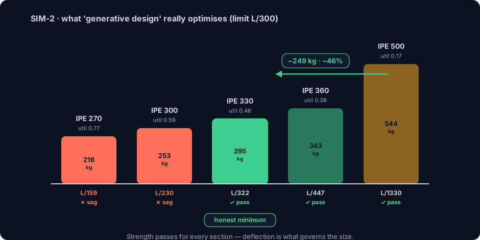
Keep the demand from Example 1 (L = 6 m, w = 25 kN/m) and the constraints an optimiser would be given — bending strength and a deflection limit of L/300. Now let it shop the rolled IPE range. The FEM engine sizes each candidate:
- IPE 270 (216 kg): strong enough (utilisation 0.77) but sags to 37.8 mm = L/159 — fails deflection.
- IPE 300 (253 kg): utilisation 0.59, deflection 26.1 mm = L/230 — still fails deflection.
- IPE 330 (295 kg): utilisation 0.46, deflection 18.6 mm = L/322 — the lightest section that passes both. The honest minimum.
- IPE 360 (343 kg): utilisation 0.36, deflection L/447 — passes with room.
- IPE 500 (544 kg): the "play-it-safe" pick — utilisation 0.17, deflection L/1330. Passes by a mile, and weighs 544 kg.
Two lessons the optimiser makes obvious. First, strength passed for every section — even the IPE 270 at 0.77 — yet the two lightest are unusable because deflection governs. An "optimiser" that only checked strength would have shipped a bouncy floor. Second, the over-cautious IPE 500 is 249 kg heavier than the right-sized IPE 330 — 46% more steel — for zero benefit on this span.
This is what generative design actually does when it works: it finds that honest minimum because a correct analysis told it which constraint governs. Feed it a bad analysis or the wrong constraints and it will confidently optimise the wrong thing. The intelligence that matters is in the mechanics and the constraints — not in the word "generative." See deflection limits for the serviceability rules doing the governing here.
Worked example 3: the frame an LLM can't solve
A single simply supported beam is determinate — statics alone gives the answer, so an LLM can sometimes get it right by reciting a formula. A real building is not that. It is a statically indeterminate frame: moments redistribute between beams and columns, wind has to find a path to the ground, and there is no closed-form equation to recite. This is where pattern-matching AI runs out of road and a real solver is the only option.
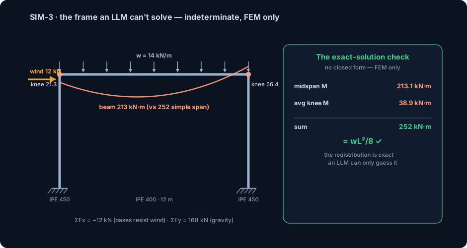
Model a portal frame: 12 m span, 6 m eave height, two IPE 450 columns and an IPE 400 beam, rigid welded knees and fixed bases, under gravity w = 14 kN/m on the beam plus a 12 kN lateral wind push. The direct-stiffness FEM engine reports:
- Equilibrium: ΣFx = −12 kN (the fixed bases absorb the entire wind push) and ΣFy = 168 kN (= 14 kN/m × 12 m of gravity). The reactions balance to the newton.
- Redistribution: the beam's peak moment is 213.1 kN·m — well below the 252 kN·m a simple span would see (wL²/8), because the rigid knees pull moment out of the span and into the corners.
- Wind asymmetry: the push makes the frame lean, so the two knees differ — 21.3 kN·m on the windward side, 56.4 kN·m on the leeward — and even the vertical reactions split unevenly (81.1 kN vs 86.9 kN). Hand methods struggle here; FEM does it instantly.
Now the proof that the machine is right, not just fast. For any beam, the midspan moment plus the average of the end moments must equal wL²/8. Check it: 213.1 + (21.3 + 56.4)/2 = 213.1 + 38.9 = 252.0 kN·m = wL²/8, exactly. The redistribution is not approximate — it is the exact solution of the indeterminate structure, and the identity confirms it. An LLM can describe redistribution in words; it cannot produce that number. Only the deterministic solver can — which is precisely why a real structural tool cannot be a chatbot.
ML and surrogate models: fast, but only as true as their training
Between "ask a chatbot" and "run a full analysis" sits a genuinely powerful idea: the surrogate model. Train a neural network on thousands of solved FEM cases and it learns to predict the outputs — a utilisation, a natural frequency, a peak drift — in milliseconds, without solving the equations. For optimisation loops that need to evaluate ten thousand candidates, or for real-time what-if during early design, that speed is transformative.
But a surrogate has three limits an engineer must respect:
- It interpolates; it does not understand. Inside the range of its training data it can be remarkably accurate. Push it outside that range — an unusual span, a new material, a load case it never saw — and it fails silently, returning a confident number with no warning that it is extrapolating.
- It needs FEM as both teacher and referee. The training data comes from a deterministic solver, and the final design must be checked by one. The surrogate accelerates the search; it does not get the last word.
- Its errors are statistical, not physical. A surrogate can violate equilibrium by a little and never notice. Physics-informed machine learning — which bakes the governing equations into the training — is the promising middle path, but it narrows the gap rather than closing it.
The right mental model: ML proposes fast, FEM verifies exactly, and the engineer owns the envelope. A surrogate is a brilliant scout and a poor judge — use it to explore, never to sign off.
The limits: verification, liability and the engineer of record
The hardest limits on AI in structural engineering are not technical — they are professional. A model's output is not a design; a licensed engineer's stamp is. The standard of care does not change because a neural network produced the geometry, and "the AI told me to" is not a defence a court, a client or a collapsed structure will accept.
The risks worth naming plainly:
- Confident hallucination. LLMs generate the most plausible answer, not the correct one, and they never signal doubt. A wrong section can read exactly like a right one.
- Black-box opacity. If you cannot explain why a result is what it is, you cannot defend it — and increasingly cannot get it approved. Traceability is not optional in a safety-critical field.
- Garbage in, garbage out. A model trained on biased, sparse or mislabelled data will be confidently wrong on exactly the cases you did not anticipate.
- Automation complacency. The more polished the tool, the easier it is to stop checking. That is precisely when a silent error ships.
None of this is an argument against AI — it is an argument for keeping the engineer in charge of the verification. Treat every AI output the way you would treat a calculation handed to you by a talented but unproven junior: understand it, check the governing cases against a real analysis, and take personal responsibility for the number before it leaves your desk. Responsible-AI frameworks for the field say the same thing in more words: the human, not the model, is accountable.
From AI-assisted intent to a verified design in CalcSteel
Put the two halves together and you get the workflow that actually works: let AI move at AI speed on the parts it is good at, and pin every structural number to a deterministic engine. That is exactly the shape of CalcSteel:
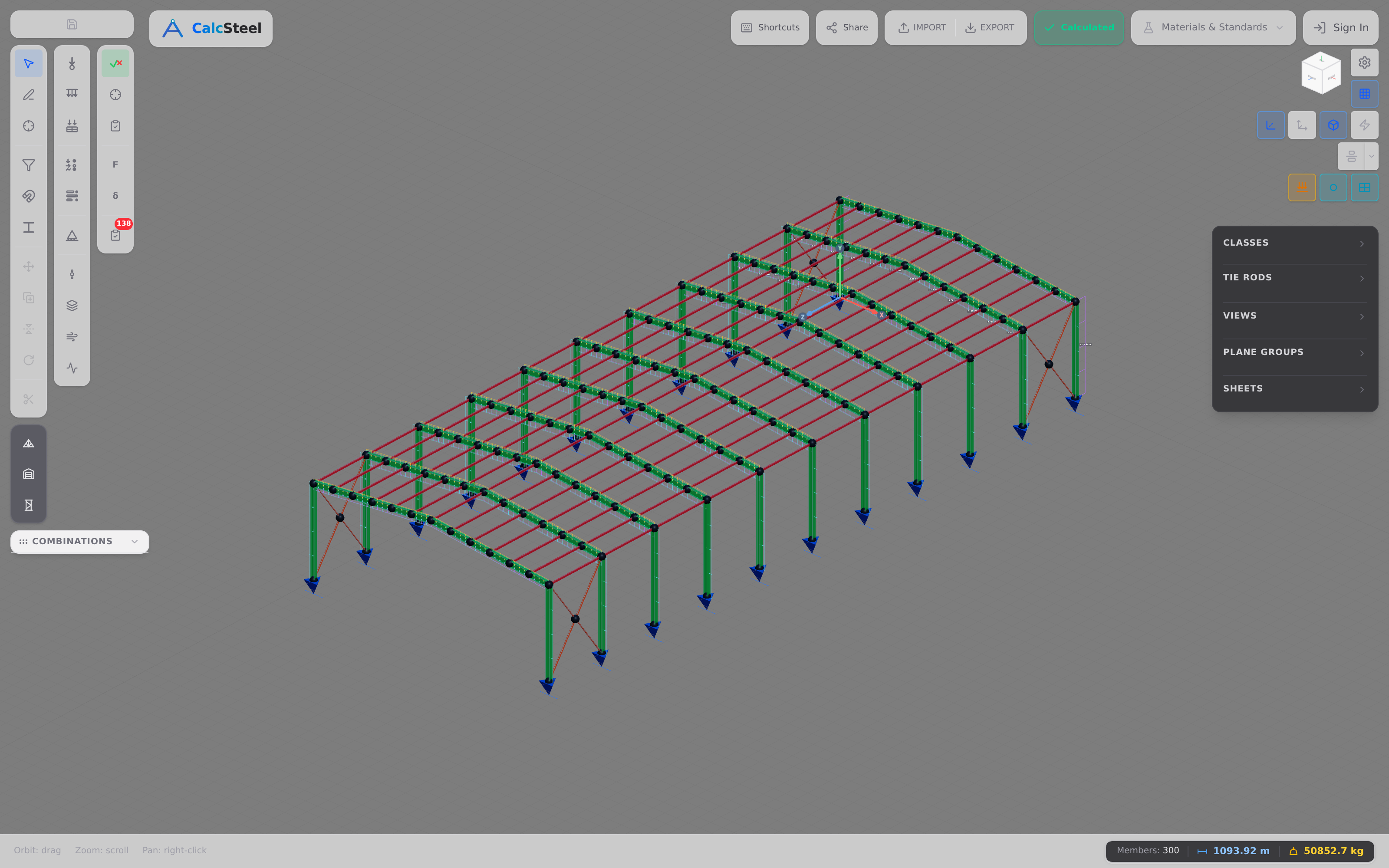
- Model and analyse the real structure with a genuine FEM engine — the direct-stiffness method from 1956, running in your browser — including the indeterminate frames of Example 3 that no chatbot can solve.
- Verify every member against your chosen code — NBR 8800, AISC 360 or EN 1993 — with the section classified and the utilisation computed, not asserted.
- Read the result at a glance. Members are coloured green-to-red by utilisation, so an over-designed member (wasting steel, like the IPE 500) is as obvious as an overloaded one — the honest feedback an optimiser, or an AI, needs to be trusted.
- Move fast without hallucinating. You get AI-speed iteration with FEM-grade rigour: the solver never invents a number, and every diagram is reproducible.
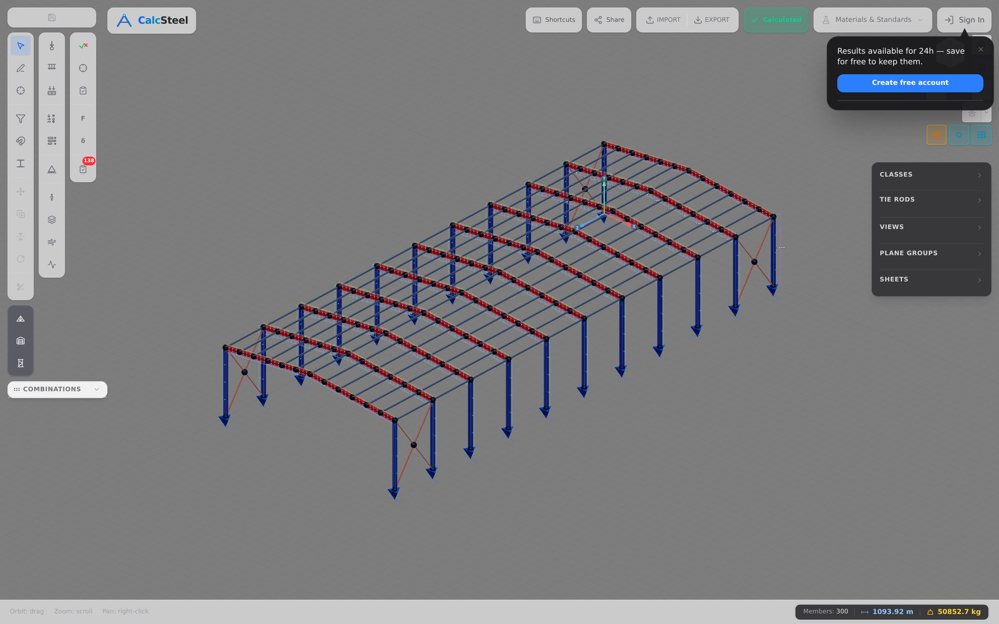
The columns that carry both axial load and frame moment are checked with an interaction equation, never bending alone — see combined axial and bending. And the repetitive, stackable frames that make AI-driven parametric design so effective are covered in modular steel construction. CalcSteel is the deterministic verifier your AI-assisted workflow needs — the place where a fast idea becomes a checked design.
Common mistakes & FAQ
Six mistakes that turn AI from an asset into a liability
- Trusting an LLM's number without a solver check. The text is fluent, the section modulus may be invented. Every beam, load and capacity a model gives you goes into a real analysis before you believe it.
- Assuming AI removes the physics. It removes labour, not mechanics. Equilibrium and the code check are still what decide safety — Example 1 passed only because the engine confirmed it.
- Using a surrogate outside its training range. An ML model extrapolates silently. Off-distribution, its confident answer is worthless; verify with FEM.
- Sizing on strength when deflection governs. The optimiser in Example 2 would have shipped an IPE 270 on strength alone — L/159, a bouncy failure. Miss the governing limit and AI just reaches the wrong answer faster.
- Forgetting who is liable. The model is not stamped; you are. The standard of care is unchanged by the tool that drew the geometry.
- Treating 'generative design' as magic. It is constrained optimisation over a real analysis. Feed it the wrong constraints or a bad model and it optimises the wrong thing, beautifully.
FAQ
Will AI replace structural engineers? No — it changes the job. AI automates drafting, lookup and first-pass exploration; it cannot take professional responsibility, solve an indeterminate frame without a real solver, or replace engineering judgement. The engineer moves up the stack, from producing numbers to specifying intent and verifying results.
Can I use ChatGPT to design a beam? To explore and explain, yes; to certify, no. As Example 1 showed, an LLM can propose an IPE 330 — but only a deterministic solver confirms R = 75 kN, M = 112.5 kN·m and the deflection. Always check the number in a real calculator.
Is generative design real, or hype? Real, when it is constrained optimisation over a correct analysis (Example 2). Hype, when it is presented as intelligence that removes the need to understand what governs the design.
Does CalcSteel use AI? The structural core is deterministic FEM by design — no member force is ever produced by a language model. That is the point: it is the verifier your AI-assisted workflow can trust.
Key takeaways
- AI is a fast layer on a fixed foundation. LLMs, ML surrogates, generative design, computer vision and automation accelerate the work — none replaces the deterministic mechanics core underneath.
- LLMs predict text, not forces. Our IPE 330 beam is trustworthy only because a real FEM engine reproduced R = 75 kN, Mmax = 112.5 kN·m and δ = L/322 to the decimal.
- 'Generative design' is constrained optimisation. Strength passed for every section; deflection governed. The honest minimum was an IPE 330 — an IPE 500 wastes 46% of the steel.
- Only FEM solves the real frame. The indeterminate portal redistributed 252 → 213 kN·m, and 213.1 + 38.9 = 252 = wL²/8 exactly — an identity an LLM can only guess at.
- AI proposes, mechanics disposes. The engineer of record verifies, stamps and owns every number.
Check any AI's beam right now in the free beam calculator — unlimited, no login for the math — then model, verify and right-size the whole structure in CalcSteel and let a real FEM engine turn a fast idea into a design you can defend. Students get everything unlocked, free, through /education.
Sources
- 1.Vaswani et al. (2017) — Attention Is All You Need (the transformer behind modern LLMs)
- 2.Salehi & Burgueño (2018) — Emerging artificial intelligence methods in structural engineering (Engineering Structures)
- 3.Responsible AI in structural engineering: a framework for ethical use (Frontiers in Built Environment, 2025)
Try CalcSteel for free
Model, analyze and design steel structures in your browser. No install, no signup.
Open the 3D editor