Modular Steel Construction: Module to Tower
Modular steel construction: from a single volumetric steel module to a stacked tower — reactions, deflection, load paths. Try the free steel-weight calculator.
Key takeaways
- A module is a box that loads only at its four corners — the corner posts and their connections carry everything, so design them first.
- Modular floors are governed by deflection and vibration, not bending: our floor beam passed strength at utilisation 0.43 but failed at 25.95 mm (L/231).
- Axial rarely caps stack height — the ground corner post saw 72 kN against a squash near 1727 kN; the real limits are the inter-module joints and the lateral core.
- Only FEM finds the rigid-frame redistribution: welded corners pulled ~31% of moment out of the span into the posts and bases under gravity plus a 6 kN wind push.
- One 6×3.6×3.15 m module is about 2.35 t of steel (~108.8 kg/m²) — and you can reproduce every member in the free steel-weight calculator.
Modular steel construction — from a single steel module to a stacked tower
A mid-rise building rising in weeks, not years — steel boxes trucked in finished, craned up and bolted together like flat-pack furniture. That is modular steel construction: the structure is assembled on site, not built.
This is the definitive walkthrough, from one steel module to a stacked tower. Every structural number here comes from a real FEM engine — reactions, bending moments, deflections, axial load paths, sidesway — and there is a live steel-weight calculator embedded further down so you can weigh a module member by member yourself.
We wrote it for three readers:
- Engineering students — see the closed-form checks and where they stop working (indeterminate frames need FEM).
- Practicing engineers — the load path, the connections, the lateral system, the governing limit states.
- Curious builders — why factory boxes go up so fast, and what actually holds the stack together.
One thing to fix before we start: modular is not the same as prefab. Here, modular means volumetric — factory-built, prefinished three-dimensional steel room boxes that are stacked. That is a different animal from a flat-pack, pre-engineered portal-frame shed, which we cover in its own sibling article: prefab steel buildings (PEMB). Don't blur the two.
What modular steel construction actually is
Modular steel construction is a method in which a building is made from factory-built, prefinished volumetric steel modules — each a braced box of RHS corner posts, edge-beam rings and floor and ceiling joists — that are transported to site and stacked and bolted together. The building is assembled from finished rooms, not built stick by stick.
The key word is volumetric: a module is a real, enclosed three-dimensional room — often already carrying its floor, ceiling, cladding, services and finishes when it leaves the plant. Structurally it is a steel box whose job is to be stiff enough to survive lifting and transport, then hand its loads cleanly to the box below.
Three families of "modular" show up in practice:
- Volumetric (PPVC — Prefabricated Prefinished Volumetric Construction): full 3D steel room boxes, stacked. This is what this article models.
- Panelised: flat, factory-made wall, floor and roof panels shipped flat and assembled into rooms on site — faster than stick-build, but not a finished box.
- Podium-plus-modular: a conventional concrete or steel podium (retail, parking, transfer level) with volumetric modules stacked above — very common for mid-rise residential.
Throughout, we use RHS and SHS hollow sections for the module members, because closed sections give the torsional stiffness and clean four-corner load paths that stacking demands.
From capsules to towers: a short history
Volumetric building is not new — but structural steel is what let it grow tall.
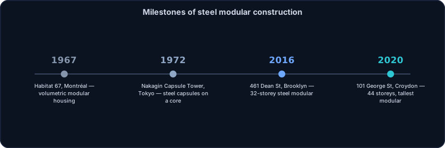
- 1967 — Habitat 67, Montréal (Moshe Safdie). A landmark of volumetric housing: prefabricated boxes stacked and interlocked into a terraced complex, built for Expo 67. It proved the idea that finished dwelling units could be assembled from repeated modules.
- 1972 — Nakagin Capsule Tower, Tokyo (Kisho Kurokawa). Individual steel capsules bolted to two concrete cores — an icon of Metabolist architecture and an early demonstration of module-to-core attachment as the structural strategy.
- 2010s — high-rise steel modular matures. Improved inter-module connections, tolerance control and lateral systems moved modular from low-rise into genuinely tall buildings.
- 2016 — 461 Dean Street, Brooklyn. Around 32 storeys of steel-framed modules; at completion it was widely reported as the world's tallest modular building at the time.
- 2020 — 101 George Street, Croydon, London. Two steel-framed modular towers reaching roughly 44 storeys, reported on completion as the tallest modular building — again built from steel-framed volumetric modules.
The through-line: as modules got taller, the engineering attention shifted away from the individual box and toward the connections between modules and the lateral system that keeps the stack standing.
Anatomy of a steel module
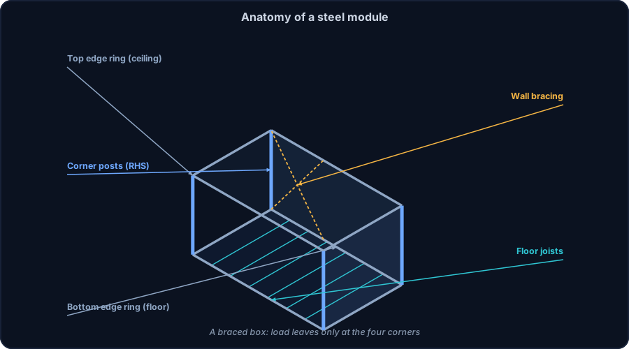
Strip a module back to its steel and you get a braced box. Six ingredients:
- Four RHS corner posts — the vertical spine of the module and the only route gravity takes downward.
- A top edge-beam ring — four RHS beams framing the ceiling, tying the tops of the posts together.
- A bottom edge-beam ring — four RHS beams framing the floor, tying the post feet together.
- Floor joists spanning between the long bottom edge beams — they carry the occupants.
- Ceiling joists spanning the top ring.
- Wall bracing — diagonals or braced wall panels that stiffen the box against racking during lift, transport and in service.
Here is the single most important structural idea in the whole method: load leaves a module only at its four corners. The edge rings collect the floor and ceiling loads and funnel everything into the corner posts; the posts hand it to the module below at four discrete points. So the corners — and the connections at those corners — are everything. Get them right and the stack behaves; get them wrong and nothing else matters.
One detail that trips people up: where two modules meet, you get a doubled floor/ceiling zone — the ceiling framing of the lower module sits directly beneath the floor framing of the upper one. That is two full layers of steel and structure at every inter-module interface, which affects both the storey build-up and the weight takeoff.
Worked example 1: the module floor beam (deflection governs)
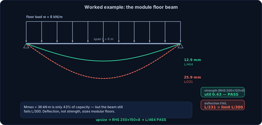
Start where the load starts: the floor. Take a single residential module floor line and model one edge beam as a simply supported RHS 200×120×8, spanning L = 6.0 m, carrying a uniform floor load of w = 8 kN/m. This is the bread-and-butter member of every volumetric module.
The statics are clean, and the CalcSteel FEM engine reproduces the closed form to three decimals:
- End reactions: R = wL/2 = 24 kN at each support.
- Peak shear: Vmax = 24 kN at the supports.
- Peak moment: Mmax = wL²/8 = 36.0 kN·m at midspan.
Now check strength. For an S355 section the elastic bending capacity is MRd,el ≈ 83.9 kN·m. That gives a strength utilisation of just 0.43 — a huge margin. If bending were the whole story, you could halve the section and still pass.
But bending is not the whole story. The midspan deflection is 25.95 mm, which is span/231. The engine matched the closed form 5wL⁴/384EI to three decimals. Compare that against the usual serviceability limits:
- L/300 → 20 mm limit — FAILS.
- L/360 → 16.7 mm limit — FAILS.
So the beam is nowhere near its strength limit yet already breaks its deflection limit. Deflection governs. Upsize to a deeper RHS 250×150×8 and the deflection drops to 12.9 mm = span/464, which passes comfortably. The extra depth buys stiffness, and stiffness is what modular floors actually need.
Why modular floors are deflection- and vibration-critical
Three things push modular floors into the serviceability regime. First, shallow floor zones: modules are dimensioned to fit on a truck, so designers fight for every millimetre of structural depth — shallow means flexible. Second, occupant comfort: residential floors are judged by how they feel underfoot, so bounce and footfall vibration matter as much as sag. Third, the doubled floor where two stacked modules meet adds mass but not necessarily the span stiffness that controls dynamic response.
The lesson generalises: on a module floor, size for stiffness first and confirm strength second. For the limits and how to apply them, see deflection limits and serviceability: deflection and vibration.
Worked example 2: the stacked load path
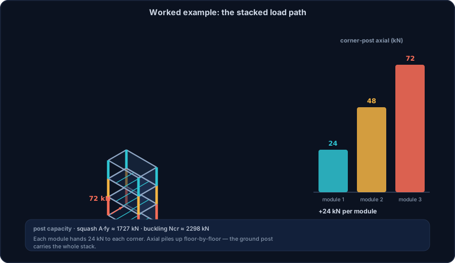
Load leaves a module only at its four corners, so follow the corners down the stack. Take three volumetric modules stacked on RHS 200×120×8 corner posts, each box 6.0 m × 3.6 m at a 3.15 m storey height, with the same w = 8 kN/m on each long floor beam.
Each module delivers 24 kN to each of its four corners (the same 24 kN reaction from SIM-A). Stack them, and the corner-post axial force builds floor by floor:
- Top module post: 24 kN.
- Second-storey post: 24 + 24 = 48 kN.
- Ground-storey post: 48 + 24 = 72 kN.
The engine confirms the ground corner reaction: Fy = 72 kN = 3 × 24 kN. Clean, verifiable, and exactly what hand statics predict.
Why axial almost never limits the height
Now size the corner post. For S355 the squash capacity is A·fy ≈ 1727 kN, and the Euler buckling load over the 3.15 m storey is Ncr ≈ 2298 kN. Against a demand of 72 kN, a single corner post could carry dozens of storeys of this loading before axial crushing or buckling governs.
So the corner post is not what caps a modular tower. The real limits are:
- The inter-module connections — the bolted corner castings and tie plates that must transfer compression, shear, tension, and uplift between stacked and adjacent modules.
- The lateral system that resists wind and seismic (covered in the lateral-system section).
Robustness and tie forces
There is one more reason the connections dominate: robustness. After the 1968 Ronan Point collapse, codes require tie forces so that losing one element does not trigger disproportionate, progressive collapse. In a stack of discrete boxes, those horizontal and vertical ties run through the inter-module joints — which is exactly why designers detail them so carefully. The post has margin to spare; the joints hold the building together.
Weigh your module: the live calculator
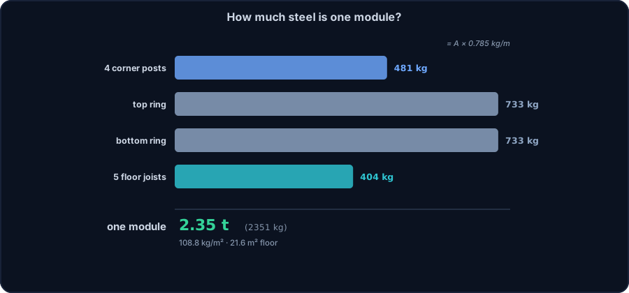
How much steel is one module? Take the frame of a single 6.0 × 3.6 × 3.15 m box and add it up:
- Four RHS 200×120×8 corner posts — 481 kg total.
- Top edge ring, RHS 200×120×8 — 733 kg.
- Bottom edge ring, RHS 200×120×8 — 733 kg.
- Five floor joists, RHS 150×100×6 — 404 kg.
That is ≈ 2351 kg = 2.35 tonnes of steel per module, or about 108.8 kg per m² over the 21.6 m² floor. A useful benchmark to carry in your head.
Every one of those numbers is just length × mass-per-length, and the mass-per-length is kg/m = A[cm²] × 0.785. Reproduce each member yourself in the embedded steel-weight calculator right here — enter the section and length, and watch the totals build up. The math is unlimited, free, and needs no login.
For the theory behind the formula and how section area drives mass, see structural steel weight.
Selected profile
This page ships 1,320 mill-catalog sections offline. The full CalcSteel database — 1,300+ profiles including NBR 6355 cold-formed — lives in the profile database and the 3D editor.
Nominal vs. rolling tolerance — W150x13
Permitted delivered-mass band per product standard. Invoices settle on the nominal kg/m; the band is what an incoming-inspection scale may legitimately read.
W = kg/m × L × n = 13 kg/m × 6 m × 1 = 78 kg
Total weight
78 kg
Unit weight
13 kg/m
Every input above — profile, dimensions, cut list, price — travels in the link.
Worked example 3: the module as a rigid frame
The floor beam in Example 1 was a simple beam because we let it be one. A real steel module is not a collection of simple beams. Its corners are welded and its feet are fixed or bolted down, so the whole box acts as a rigid frame. That changes where the moments go — and it makes the frame statically indeterminate. There is no closed-form answer here; only a FEM engine can solve it.
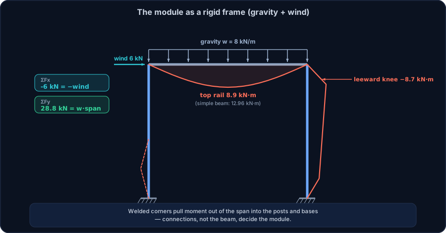
So we modelled the module bent directly: two corner posts RHS 200×120×8, 3.15 m tall, a top rail RHS 200×120×8 spanning 3.6 m, rigid welded corners, fixed bases. Loading is gravity on the rail (w = 8 kN/m) plus a lateral wind push of 6 kN at the eave.
First the equilibrium check the engine reports:
- ΣFx = −6 kN — the fixed feet resist the entire wind push. The base connections, not the roof, take the horizontal load.
- ΣFy = 28.8 kN — that is 8 kN/m × 3.6 m, the gravity load, delivered straight to the bases.
Now the payoff. If the top rail were a simple beam, its midspan moment would be wL²/8 = 12.96 kN·m. In the rigid frame the engine finds a peak rail moment of only 8.89 kN·m. The welded corners have pulled roughly 31% of the span moment out of the rail and pushed it into the posts and bases. The beam gets easier; the connections get busier.
The wind makes the frame sway sideways, and that sidesway is asymmetric — the two knees and two bases do not share equally:
- The leeward knee carries −8.7 kN·m, and its base carries 7.26 kN·m.
- The windward base carries 2.93 kN·m.
That imbalance is the whole point. The lateral load does not divide neatly; it concentrates in the welded knee and the leeward base. Size the beam by its 8.89 kN·m and forget the knee, and you have designed the one detail that actually decides whether the module stands.
This is the modular lesson stated structurally: the connections carry the redistribution. The corner castings, the welded knees and the hold-down bases are not accessories to the frame — they are the frame's stiffness and strength. A single module is a small rigid-frame problem, and the same engine that solves a full portal frame solves it, including the sway amplification you would confirm with a second-order P-Δ check.
The lateral system: modules can't do it alone
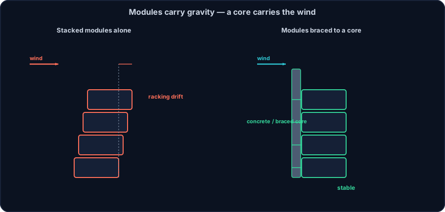
A stack of modules is superb at one job: carrying gravity straight down through its corner posts, as Example 2 showed. Ask that same stack to resist wind and earthquake, and it struggles.
The reason is in the geometry. Between modules the columns are discontinuous — a post stops at the top of one box and a new post starts at the bottom of the box above, joined by a bolted connection that is realistically semi-rigid, not a continuous moment column. Push that stack sideways and it racks: each inter-module joint gives a little, the drifts add up floor by floor, and there is no continuous frame to fight it. Example 3 already showed how hard a single welded knee works under just 6 kN of push; multiply that across a tower and the stack alone cannot keep drift and P-Δ under control.
So real modular towers do not ask the modules to be the lateral system. They give the building a stiff spine and let the modules hang gravity off it:
- A concrete core (lift and stair shafts) that the modules bolt or brace back to — the approach behind the tallest steel-modular towers.
- A braced-steel frame or dedicated bracing bays running the full height.
- A podium — a stiff lower structure that the modular stack sits on, common where the ground floor wants open, column-light space.
Whatever the spine, the floors have to deliver the wind to it. That is diaphragm action: each floor level ties the modules together and drags the lateral load horizontally into the core or bracing, which then carries the overturning down to the foundation. Without a competent diaphragm the core is stiff but unfed, and the far modules go along for the ride unrestrained.
Design the lateral system first, then the modules are free to be what they are best at — repeatable gravity boxes. If you are choosing between cores, X-bracing and moment frames, the trade-offs are the same ones in bracing systems for steel, and the pressures that feed them come from the wind load path.
From module to tower
Everything so far has been one box. A modular building is that box, repeated and stacked — but you cannot scale it up on paper alone, because the module's real limits are set off the drawing board, in the factory and on the road.
Transport governs the module's shape. A volumetric module has to fit on a truck and under bridges, so its width is typically about 3.0–4.0 m and its length about 6–12 m. That is why the box we analysed is 6.0 m × 3.6 m: it is a room-sized unit that a lorry can legally carry. Want a wider room? You join two modules side by side on site — you do not build a wider box you cannot deliver.
Craneage governs the sequence. Each finished module — around 2.35 t of steel frame before you add floors, walls, services and finishes — is lifted into place and bolted at its four corners. Lift capacity, reach and the choreography of stacking set the pace of the build.
Tolerances govern the fit. Modules are prefinished in a controlled factory, so the corner posts and connection points have to align millimetre-close across dozens of units. That factory QA is what lets the crew assemble — not build — a mid-rise building in weeks, stacking boxes like flat-pack furniture.
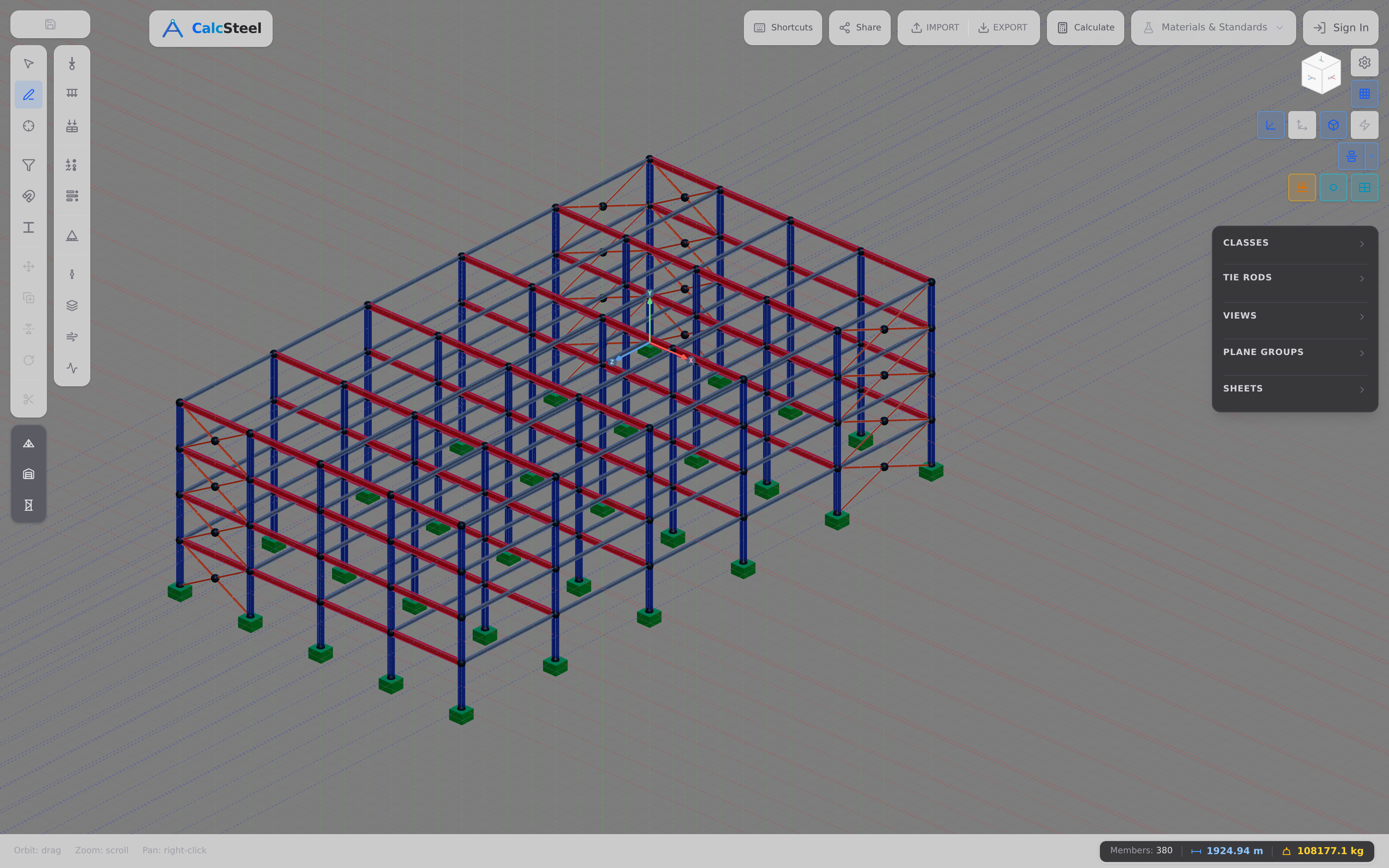
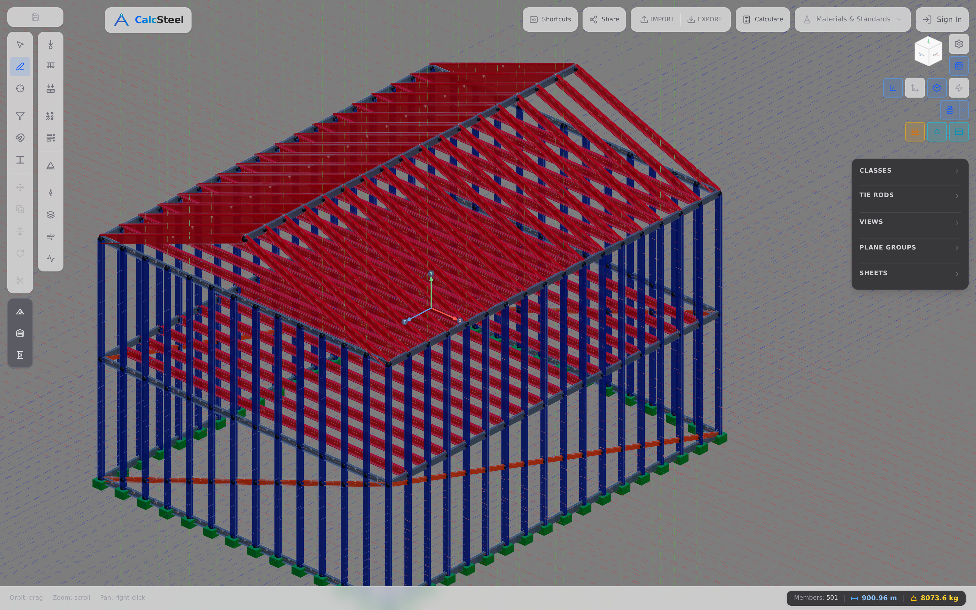
And the frame you stack is a genuine engineering model, not a cartoon. The module in Examples 1 to 3 is a real steel frame of RHS members that you model, load and analyse in the CalcSteel 3D editor — reactions, moments, deflection and axial, every number from the FEM engine.
Keep one distinction sharp as you scale up. This article is about volumetric modular steel — prefinished 3D room-boxes, transported whole and stacked. That is not the same as a flat-pack pre-engineered portal-frame building (a PEMB), where columns, rafters and cladding ship as loose members and are erected into a single-storey shed on site. Both are prefabricated steel, but the structure, the load path and the erection are different animals — see the sibling article on prefab steel buildings. Modular stacks room-boxes into towers; PEMB assembles frames into sheds.
From model to design: sizing & verifying every member
A finite-element model gives you forces and displacements. Turning those into a safe, code-compliant module is a second, disciplined step — and it is where most beginners stop too early. Every member has to be sized, classified and verified, not just drawn.
From moment to section
Start with strength. A beam's required elastic section modulus is W ≥ M / fyd. Take the module floor beam from Worked Example 1: Mmax = 36.0 kN·m (= wL²/8). Against an elastic bending capacity of about 83.9 kN·m in S355, the RHS 200×120×8 sits at a strength utilisation of only 0.43. On paper it is barely working. Yet it fails serviceability — 25.95 mm of sag, L/231, worse than the L/300 limit. Strength alone would have shipped a bad floor.
Corner posts: axial and bending together
The corner posts are not pure columns. They carry the accumulated stack axial (72 kN at the ground post in Worked Example 2) and the frame moments the rigid corners attract (a leeward knee at −8.7 kN·m and a base at 7.26 kN·m in Worked Example 3). That is a combined axial-plus-bending problem, checked with an interaction equation — never bending alone. See combined axial and bending for the full N-M interaction.
Classification, deflection and vibration
- Section classification. Whether you may use the plastic modulus Z or must fall back to the elastic Wel depends on the class of the section. Slender RHS walls buckle locally before yielding — the code decides which modulus is legal.
- Deflection. Floors are governed by L/300 or L/360, not strength. The RHS 200×120×8 fails; the deeper RHS 250×150×8 reaches 12.9 mm = L/464 and passes.
- Vibration. Shallow, doubled modular floors also need a natural-frequency / footfall check for occupant comfort — a limit that lives beyond any single stress number.
The utilisation ratio
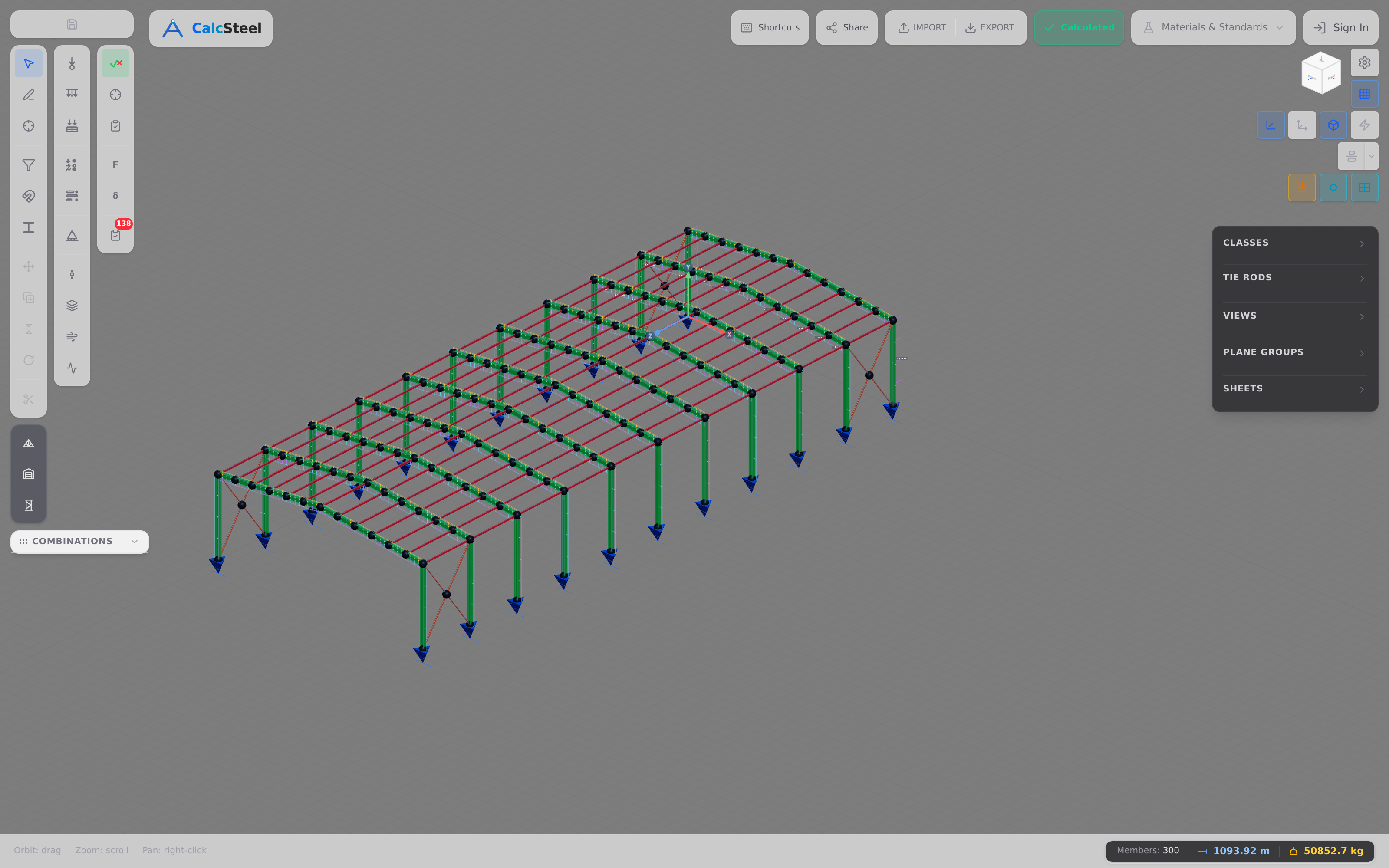
Every check reduces to one honest number: the utilisation ratio, demand over capacity. Below 1.0 passes; above 1.0 fails. CalcSteel runs the same FEM you would solve by hand, classifies each section, applies your chosen code — NBR 8800, AISC 360 or EN 1993 — and colours every member from green to red by utilisation, so the governing member in a stacked model is impossible to miss.
Common mistakes & FAQ
Six mistakes that break modular models
- Treating inter-module joints as rigid. Bolted corner castings and tie plates are semi-rigid at best. Model them as rigid and you will under-predict sidesway and mis-place the moments — the joints, not the beams, decide the stack.
- Sizing floors on bending strength. The module floor beam passed strength at utilisation 0.43 yet failed deflection (25.95 mm, L/231). Deflection and vibration govern shallow modular floors — check them first.
- Forgetting the lateral core. Stacked modules are strong in gravity and weak laterally. Without a concrete or braced-steel core, or a podium, the stack racks under wind and seismic.
- Ignoring transport and lifting load cases. A module is craned, trucked and set down before it ever carries a floor. Handling and lifting can be the governing load case — model them.
- Mishandling the doubled floor/ceiling. Where modules stack, two rings of framing meet — a ceiling ring over a floor ring. Double-count it and you inflate the steel; forget it and you lose stiffness.
- Skipping robustness tie forces. Disproportionate-collapse rules (post-Ronan Point thinking) demand tension ties between modules so the loss of one support does not unzip the stack. These are separate from gravity design.
FAQ
Is modular steel construction cheaper? Not always on raw steel tonnage — a module carries doubled floor/ceiling framing and corner posts sized for stacking and handling. It wins on time: factory fabrication runs in parallel with site works, and assembly happens in weeks, not months. The saving is programme and predictability, not kilograms.
How tall can modular steel buildings go? Taller than most people expect — steel-framed modular towers have reached into the forties of storeys (see the history section). The ceiling is set by the inter-module connections and the lateral system, not the corner post: a single RHS 200×120×8 post has a squash capacity near 1727 kN and Euler buckling near 2298 kN, enough for dozens of storeys of this loading before axial governs.
What is the difference between modular and prefab (PEMB)? Modular here means volumetric — factory-finished 3D room boxes, stacked and bolted on site. A pre-engineered portal-frame building ships as flat members and cladding and is built on site as a 2D frame. Both are prefabricated steel, but the module is a box and the PEMB is a frame — do not blur them.
What steel sections are used for modules? Overwhelmingly RHS and SHS hollow sections — clean four-sided faces for corner posts, edge-beam rings and floor joists, easy to weld into a closed box and to stack corner-on-corner. The worked examples above use RHS 200×120×8 for the box frame and RHS 150×100×6 for the floor joists.
Key takeaways
- A module is a box that loads only at its four corners. The corner posts and their connections carry everything — design them first.
- Modular floors are governed by deflection and vibration, not bending. Our floor beam passed strength at utilisation 0.43 but failed at 25.95 mm (L/231); a deeper RHS 250×150×8 fixed it.
- Axial rarely limits stack height. The ground corner post saw 72 kN against a squash near 1727 kN — the real limits are the inter-module joints and the lateral core.
- Only FEM finds the rigid-frame redistribution. Welded corners pulled ~31% of moment out of the span and into the posts and bases under gravity plus a 6 kN wind push.
- One 6×3.6×3.15 m module is about 2.35 t of steel (~108.8 kg/m²) — and you can reproduce every member yourself.
Weigh your own module now in the free steel-weight calculator — unlimited, no login for the math — then model the whole stack in the CalcSteel editor and let a real FEM engine size and verify every member. Students get everything unlocked, free, through /education.
Sources
Try CalcSteel for free
Model, analyze and design steel structures in your browser. No install, no signup.
Open the 3D editor