Green Steel Construction: Low-Carbon by Design
Green steel construction for engineers: what low-carbon steel is, why it performs identically, and how to cut a structure's embodied carbon. Try the free steel-weight calculator.
Key takeaways
- Green steel is the same steel — same grade, strength and FEM behaviour; you re-specify the production route, you don't redesign the structure.
- Embodied carbon follows the route: ≈2.3 tCO₂e/t for coal BF-BOF, ≈0.7 for scrap-EAF, ≈0.4 for green H₂-DRI — up to an 83% cut on identical members.
- Right-sizing is the engineer's biggest in-model lever: our 8 m floor beam needed only an IPE 360 (deflection L/315), not a play-it-safe IPE 500 — 37% less steel and 0.62 tCO₂e per beam.
- Only FEM sizes the real indeterminate frame: our portal (1.23 t of steel) drops from 2.84 to 0.49 tCO₂e by switching to green steel — same forces, same safety.
- Embodied carbon = mass × emission factor, and mass = A[cm²] × 0.785 × length — weigh every member and its carbon in the free calculator.
Green steel construction — the same structure, a fraction of the carbon
Steelmaking is one of the largest single sources of carbon dioxide on the planet — roughly 7–9% of global CO₂ emissions. Yet the beam that carries your floor does not care how its steel was made: an S355 section rolled in a coal-fired blast furnace and the identical section made with green hydrogen have the same yield strength, the same stiffness, and the same load capacity. What changes is not the engineering — it is the embodied carbon.
That single fact is the whole opportunity of green steel construction. You do not redesign the structure to decarbonise it — you re-specify the steel and you right-size the members. This is the engineer's guide to doing exactly that, and every structural number below comes from a real FEM engine: reactions, moments, deflections, whole-frame tonnage — each paired with the CO₂ it carries. There is a live steel-weight calculator embedded further down so you can weigh a member and estimate its footprint yourself.
We wrote it for three readers:
- Engineering students — see why low-carbon steel is the same steel structurally, and where the carbon actually hides.
- Practicing engineers — the production routes, the emission factors, how to specify low-carbon steel, and the design levers you control.
- Sustainability-minded builders — why the biggest carbon savings are decided on the drawing board, not just at the mill.
What green (low-carbon) steel actually is
Green steel — also called low-carbon or near-zero steel — is structural steel produced with drastically lower carbon-dioxide emissions, chiefly by replacing coal-based blast-furnace ironmaking with recycled-scrap electric-arc-furnace (EAF) melting or with hydrogen-based direct reduction (H₂-DRI) powered by clean electricity. The alloy, the grade and the strength are unchanged — an S355 or A992 section is still S355 or A992 — but its embodied carbon can be up to about 90% lower.
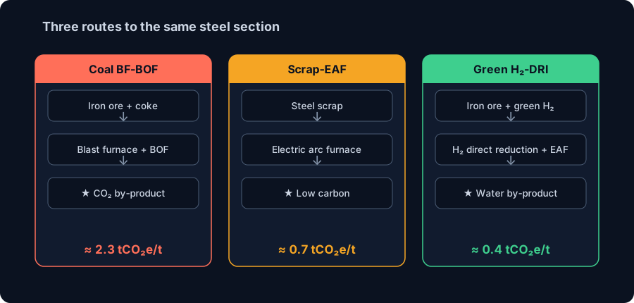
The carbon lives in how the iron is reduced. Three production routes dominate, and they are worlds apart on emissions:
- Blast furnace + basic oxygen furnace (BF-BOF): the conventional, coal-based primary route. Coke reduces iron ore and releases CO₂ as an inescapable by-product of the chemistry. This is the highest-carbon route and still makes most of the world's steel.
- Scrap + electric arc furnace (EAF): melts recycled steel scrap with electricity. No ore reduction, no coke — so emissions are a fraction of the primary route and fall further as the electricity grid decarbonises. Steel is one of the most recycled materials on Earth.
- Hydrogen direct reduction + EAF (H₂-DRI): the frontier "green" route. Green hydrogen — not coke — reduces the iron ore, and the by-product is water, not carbon dioxide. Paired with clean power and an electric furnace, it approaches near-zero emissions.
Crucially, the finished sections from all three routes meet the same EN, ASTM or NBR standards. Green steel is not a new material an engineer has to learn — it is the same steel with a different, much smaller carbon receipt.
Embodied carbon: the number that actually matters
Buildings are judged on two carbon budgets. Operational carbon is what a building emits in use (heating, cooling, lighting). Embodied carbon is what was emitted to make and build the structure — extracting, processing and fabricating the materials — and it is locked in the day the building opens. As operational energy gets cleaner, embodied carbon becomes the dominant share, and for a steel-framed building the frame is the single biggest embodied-carbon item.
Embodied carbon is measured as Global Warming Potential (GWP) in kg CO₂e per kg of material (or tonnes CO₂e per tonne). For structural steel the number is set almost entirely by the production route:
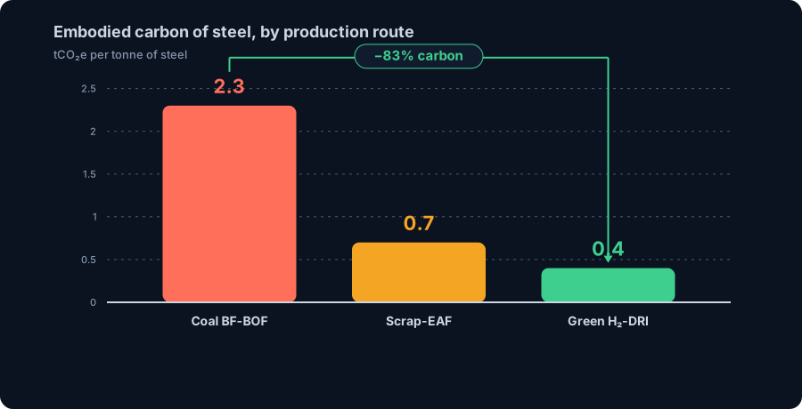
- Coal-based BF-BOF: ≈ 2.3 tCO₂e per tonne of steel (typical range ~1.9–2.5).
- Scrap-EAF: ≈ 0.7 tCO₂e per tonne (lower still on a clean grid — some EAF mills report ~0.4).
- Green H₂-DRI: ≈ 0.4 tCO₂e per tonne today, heading toward ~0.1 with fully fossil-free power — a 90–95% cut versus the coal route.
Two practical warnings. First, these are indicative factors — the honest number for a specific product comes from its Environmental Product Declaration (EPD), a third-party-verified document to EN 15804 / ISO 14025. A manufacturer-specific EAF EPD can be far below the generic database value. Second, embodied carbon is proportional to mass: GWP of a member = its mass × the emission factor. That is why the two levers an engineer actually controls are how much steel you use and which steel you specify — the rest of this guide quantifies both with real engine numbers.
From coal to hydrogen: a short history of decarbonising steel
Steel has been decarbonising, slowly then suddenly, for a century and a half.
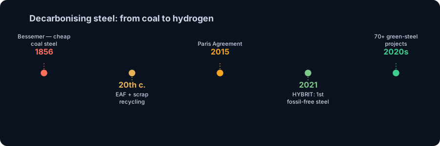
- 1856 — Bessemer process. Mass-produced cheap steel arrives and reshapes construction — but it is coal-and-coke chemistry from the start.
- 20th century — the electric arc furnace and scrap recycling. EAF steelmaking turns steel's recyclability into an industry: melt scrap with electricity instead of reducing fresh ore, and cut the carbon dramatically.
- 2015 — the Paris Agreement. Net-zero targets put the ~7–9% of global CO₂ from steel squarely in the spotlight and start the race for primary-steel decarbonisation.
- 2016–2021 — HYBRIT. The Swedish partnership of SSAB, LKAB and Vattenfall pilots hydrogen direct reduction and, in 2021, delivers the world's first fossil-free steel, made without coal, to Volvo.
- 2020s — the green-steel build-out. H2 Green Steel (now Stegra) builds a large hydrogen-DRI plant in Boden, Sweden; ArcelorMittal, Salzgitter, Tata Steel, thyssenkrupp and others commit to DRI and EAF conversions. Industry trackers count 70+ green-steel projects worth over US$130 billion in development worldwide.
The through-line: the chemistry that makes steel carbon-heavy — coke reducing iron ore — is finally being replaced by electricity and hydrogen. For the engineer specifying steel today, low-carbon supply is no longer hypothetical; it is a line item you can ask for.
Worked example 1: green steel is structurally identical
The most important engineering idea in this whole topic is also the most reassuring: low-carbon steel behaves exactly like conventional steel. Same yield strength, same elastic modulus, same section — so the analysis and the sizing are unchanged. Let a FEM engine prove it.
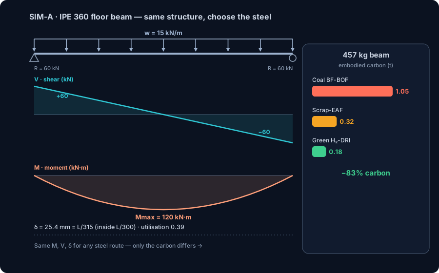
Take a typical office floor beam: a simply supported IPE 360 in S355, spanning L = 8.0 m, carrying a uniform load of w = 15 kN/m. The CalcSteel engine reproduces the closed form exactly:
- End reactions: R = wL/2 = 60 kN at each support.
- Peak shear: Vmax = 60 kN at the supports.
- Peak moment: Mmax = wL²/8 = 120 kN·m at midspan.
- Deflection: the engine reports 25.4 mm = span/315 (it includes shear deformation, which the textbook 5wL⁴/384EI slightly underestimates at ~24.2 mm). That is inside the usual L/300 limit.
Against the section's elastic bending capacity of MRd,el ≈ 310 kN·m, the strength utilisation is just 0.39. Now the point: every one of these numbers is identical whether the IPE 360 is coal-route or green-route steel, because both are S355 (fy = 355 MPa). You do not re-analyse, re-check, or up-size anything to go green.
What does change is the carbon receipt. The beam masses 57.1 kg/m × 8 m = 457 kg. Multiply by the route factor:
- Coal BF-BOF: 0.457 t × 2.3 = 1.05 tCO₂e.
- Scrap-EAF: 0.457 t × 0.7 = 0.32 tCO₂e.
- Green H₂-DRI: 0.457 t × 0.4 = 0.18 tCO₂e.
Same beam, same safety, same deflection — and 83% less embodied carbon simply by specifying the green route. That is decarbonisation with zero structural penalty.
Worked example 2: right-sizing is your biggest carbon lever
Because embodied carbon is mass × emission factor, the fastest way an engineer cuts carbon is to use less steel for the same job — and the model tells you exactly how much less. Keep the floor beam from Example 1 (L = 8 m, w = 15 kN/m, limit L/300) and shop the rolled range:
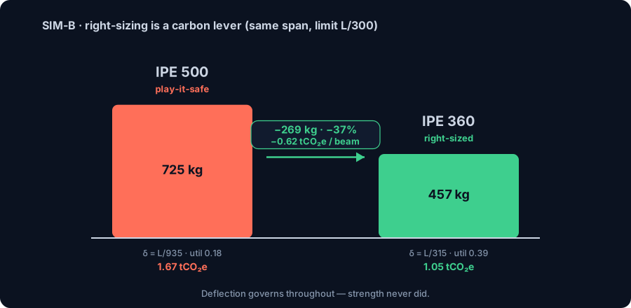
- IPE 330 (49.1 kg/m): strong enough (utilisation 0.49) but sags to 35.3 mm = L/226 — fails deflection.
- IPE 360 (57.1 kg/m): utilisation 0.39, deflection 25.4 mm = L/315 — the lightest section that passes. Deflection, not strength, sets the size.
- IPE 500 (90.7 kg/m): the "play-it-safe" pick — utilisation 0.18, deflection L/935. Passes with enormous margin, and weighs 725 kg.
The over-cautious IPE 500 is 269 kg heavier than the right-sized IPE 360 — 37% more steel — for zero structural benefit on this span. In carbon terms, right-sizing this one beam saves:
- 0.62 tCO₂e on the coal route (0.269 t × 2.3),
- and it compounds across every repeated beam in a floor plate — tens of beams, tonnes of steel, tonnes of CO₂.
Notice the hierarchy the model reveals: strength never governed — deflection did. Size by strength alone and you either ship a bouncy floor or, over-correcting, a needlessly heavy one. Only by modelling the real serviceability limit do you land on the honest minimum section. That is why efficient design is a climate decision, not just an economic one, and it is entirely in the engineer's hands. See deflection limits for the serviceability rules behind this.
Weigh your steel — and its carbon: the live calculator
Every embodied-carbon estimate starts with one number: how many kilograms of steel. And that is pure geometry — mass per metre = A[cm²] × 0.785 (steel is 7.85 g/cm³) — times the member length. Reproduce the Example 1 beam yourself in the embedded calculator: enter the section and 8 m length and watch the mass appear, then multiply by your route's emission factor to get the CO₂.
- IPE 360, 8 m → 457 kg → ×0.4 (green) = 0.18 tCO₂e; ×2.3 (coal) = 1.05 tCO₂e.
Do it for every member and you have a bottom-up embodied-carbon takeoff of the whole frame — the same method structural EPD tools use, built from parts you can verify by hand. The math here is unlimited, free, and needs no login. For the theory of how section area drives weight, see structural steel weight; to compare steel against timber on a life-cycle basis, see mass timber vs steel.
Selected profile
This page ships 1,320 mill-catalog sections offline. The full CalcSteel database — 1,300+ profiles including NBR 6355 cold-formed — lives in the profile database and the 3D editor.
Nominal vs. rolling tolerance — W150x13
Permitted delivered-mass band per product standard. Invoices settle on the nominal kg/m; the band is what an incoming-inspection scale may legitimately read.
W = kg/m × L × n = 13 kg/m × 6 m × 1 = 78 kg
Total weight
78 kg
Unit weight
13 kg/m
Every input above — profile, dimensions, cut list, price — travels in the link.
Worked example 3: model the whole frame, then decarbonise it
A single beam is easy. A real building is a frame — statically indeterminate, with moments that redistribute between beams and columns and a wind load that has to find its way to the ground. There is no closed-form answer; only a FEM engine solves it. And once you have the model, its embodied carbon is one multiplication away.
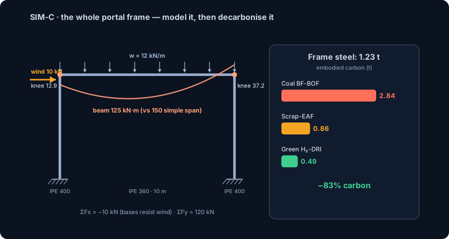
Model a portal frame: 10 m span, 5 m eave height, two IPE 400 columns and an IPE 360 beam, rigid welded knees and fixed bases, under gravity w = 12 kN/m on the beam plus a 10 kN lateral wind push. The engine reports:
- Equilibrium: ΣFx = −10 kN (the fixed bases absorb the entire wind push) and ΣFy = 120 kN (= 12 kN/m × 10 m of gravity).
- Redistribution: the beam's peak moment is 125 kN·m — below the 150 kN·m a simple span would see (wL²/8), because the rigid knees and fixed bases pull moment out of the beam.
- Wind asymmetry: the push makes the frame lean, so the two knees differ — 12.9 kN·m on one, 37.2 kN·m on the other, with the leeward base carrying 25.3 kN·m. Hand methods struggle here; FEM does it instantly.
Now weigh it. Two columns at 66.3 kg/m × 5 m plus a beam at 57.1 kg/m × 10 m give ≈ 1234 kg = 1.23 t of steel. Its embodied carbon across the routes:
- Coal BF-BOF: 1.234 t × 2.3 = 2.84 tCO₂e.
- Scrap-EAF: × 0.7 = 0.86 tCO₂e.
- Green H₂-DRI: × 0.4 = 0.49 tCO₂e.
Same frame, same forces, same safety factors — and specifying green steel turns a 2.84 t carbon footprint into 0.49 t, an 83% cut on a single small frame. Scale that across a whole building and the decision to model, right-size and re-specify becomes one of the largest carbon levers in the entire project.
How to actually specify low-carbon steel
Green intentions become real reductions only when they reach the specification. Six practical moves:
- Ask for EPDs. Require an Environmental Product Declaration (EN 15804 / ISO 14025) for the steel, and compare the product-specific GWP against generic database values — do not accept a round number.
- Set a GWP ceiling. Specify a maximum embodied carbon (kg CO₂e per kg) for the supplied sections, the way you already specify a minimum yield strength.
- Favour EAF and high recycled content. Where the structural demand allows, specify the electric-arc-furnace route and a declared recycled-content fraction.
- Seek out low-carbon and green supply. Certified low-carbon and hydrogen-route steel (e.g. ResponsibleSteel-certified or fossil-free lines) is increasingly procurable — put it in the tender.
- Reuse existing steel first. Reclaimed sections carry almost no new embodied carbon. Designing to reuse, or for future disassembly, beats even the cleanest new steel.
- Count fabrication and transport. The mill factor is the biggest term, but cutting, welding, coating and haulage add up — prefer local supply and simple, weld-light details.
None of these change the structural design. They change the carbon receipt of a structure you have already engineered — which is exactly why they are so cheap to adopt.
The engineer's decarbonisation levers, ranked
Not every carbon lever is equal, and the most powerful ones sit earliest in the design. Roughly in order of impact:
- Build less — and reuse. The greenest tonne of steel is the one you never order. Reused and reclaimed sections carry almost no new embodied carbon.
- Right-size every member. Optimise sections to the governing limit state — strength or deflection, as Example 2 showed — instead of over-speccing "to be safe". This alone routinely trims double-digit percentages of frame mass.
- Specify a low-carbon route. Swap coal-route steel for scrap-EAF or green H₂-DRI. As Example 3 showed, that is up to an 83% cut on identical members.
- Choose efficient structural systems. Sensible spans, composite floors, and hollow sections where they earn their keep move less material for the same performance.
- Design for disassembly. Bolted, demountable connections let the steel be reused at end of life — turning today's frame into tomorrow's low-carbon supply.
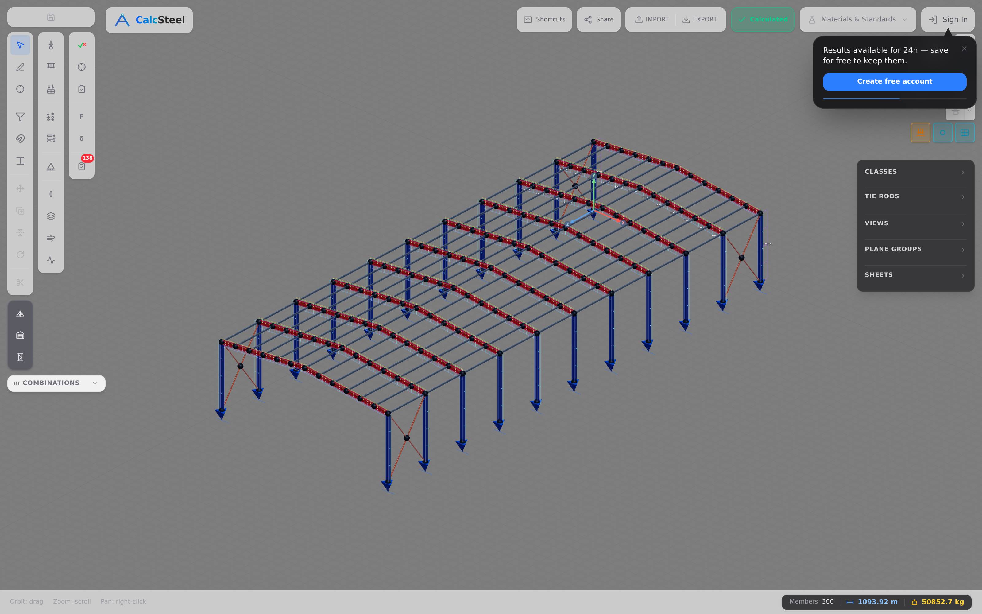
The pattern is clear: levers 1 and 2 are decided in the model, lever 3 in the specification, and all of them are things a structural engineer — not just the steelmaker — directly controls. CalcSteel is where you pull levers 1, 2 and 4: model the structure, verify it, and read off the mass you are committing to.
From model to a low-carbon design in CalcSteel
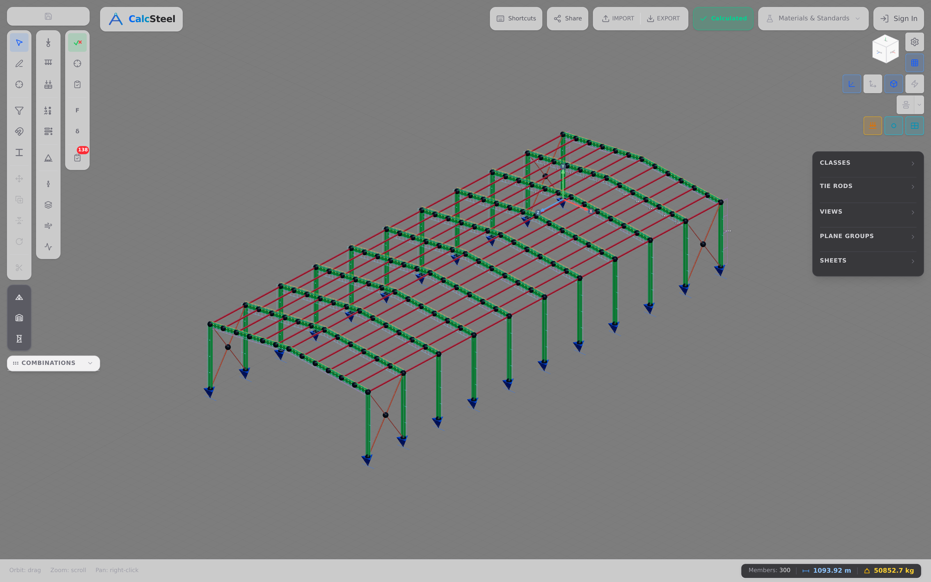
Cutting embodied carbon and passing the code check are the same workflow, not competing ones — because both reward using no more steel than the structure needs. In CalcSteel you:
- Model and analyse the real structure with the FEM engine — the indeterminate frames of Example 3 included.
- Verify every member against your chosen code — NBR 8800, AISC 360 or EN 1993 — with the section classified and the utilisation computed. Members are coloured green-to-red by utilisation, so an over-designed (carbon-wasting) member is as obvious as an overloaded one.
- Drive utilisation up honestly. A member sitting at 0.18 like the play-it-safe IPE 500 is a flashing carbon-reduction opportunity; right-sizing it toward 1.0 is both cheaper and greener.
- Weigh the result and multiply by your EPD factor for a bottom-up embodied-carbon estimate — the same arithmetic as the embedded calculator, member by member.
The combined-action members — a column carrying both the stack axial and the frame moment — are checked with an interaction equation, never bending alone; see combined axial and bending. And the repetitive, stackable frames that make prefabrication (and steel reuse) so effective are covered in modular steel construction.
Common mistakes & FAQ
Six mistakes that inflate a structure's carbon
- Believing green steel is weaker. It is the same grade and strength — S355 is S355. There is no structural penalty and no redesign; only the production route (and its carbon) changes.
- Optimising operational carbon and ignoring embodied. The frame's embodied carbon is locked in on day one. As grids clean up, it becomes the dominant budget — design for it.
- Over-speccing "to be safe". The play-it-safe IPE 500 weighed 37% more than the IPE 360 that actually passed. Margin you cannot justify is carbon you cannot justify.
- Sizing on strength when deflection governs. Our floor beam passed strength comfortably (utilisation 0.39) yet was sized entirely by L/300. Miss the governing limit and you either under- or over-build.
- Accepting round-number carbon. Generic factors are for early estimates. Demand a product-specific EPD before you claim a reduction — that is the difference between decarbonising and greenwashing.
- Forgetting reuse. Reclaimed steel beats even the cleanest new steel. Not designing for disassembly throws away tomorrow's low-carbon supply.
FAQ
Is green steel weaker or different to design with? No. Low-carbon and green steel meet the same EN/ASTM/NBR grades with the same yield strength and stiffness. As Example 1 showed, the reactions, moments and deflections are identical — you specify it, you do not redesign for it.
How much CO₂ does steel really emit? Roughly 2.3 tonnes of CO₂ per tonne of coal-route (BF-BOF) steel, about 0.7 for scrap-EAF, and around 0.4 and falling for green hydrogen steel. Steelmaking is about 7–9% of global CO₂ emissions.
Is recycled (EAF) steel the same as green steel? It is a big step — a fraction of the primary route's carbon — but "green" usually implies near-zero, which needs both recycled or hydrogen-reduced iron and clean electricity. Recycled-EAF is low-carbon; hydrogen-DRI on clean power is near-zero.
Does green steel cost more? There is currently a "green premium", but it is shrinking as capacity scales, and it is small next to the carbon it saves. Right-sizing the structure (Example 2) often pays for the premium in avoided tonnage.
What is the single biggest thing I can do as the engineer? Use less steel — reuse and right-size — and then specify a low-carbon route for what remains. Levers 1–3 above, all decided in the model and the spec.
Key takeaways
- Green steel is the same steel. Same grade, same strength, same FEM behaviour — you re-specify the production route, you do not redesign the structure.
- Embodied carbon follows the route: ≈2.3 tCO₂e/t for coal BF-BOF, ≈0.7 for scrap-EAF, ≈0.4 for green H₂-DRI — up to an 83% cut on identical members.
- Right-sizing is your biggest in-model lever. Our 8 m floor beam needed only an IPE 360 (deflection L/315), not a play-it-safe IPE 500 — 37% less steel and 0.62 tCO₂e saved per beam.
- Only FEM sizes the real frame. The indeterminate portal (1.23 t of steel) drops from 2.84 to 0.49 tCO₂e by switching to green steel — same forces, same safety.
- Weigh every member — and its carbon. Embodied carbon = mass × emission factor, and mass = A[cm²] × 0.785 × length.
Weigh your own steel now in the free steel-weight calculator — unlimited, no login for the math — then model, verify and right-size the whole structure in CalcSteel and let a real FEM engine show you exactly how much steel, and how much carbon, you are committing to. Students get everything unlocked, free, through /education.
Sources
Try CalcSteel for free
Model, analyze and design steel structures in your browser. No install, no signup.
Open the 3D editor