Steel for AI Data Centers: The Structure Behind the Compute
How structural steel carries AI data centers: real FEM worked examples, rack floor loads, 24 m roof trusses — plus a free beam calculator to try.
Key takeaways
- AI-density hall floors run 12–15+ kN/m² — four to five times office loads — with racks at 1.5–2 t each and climbing.
- Stiffness governs, not strength: the IPE 550 floor beam used only 44% of its bending capacity yet barely passed L/360 at L/379.
- At 24 m spans, rolled rafters run out of stiffness first — the IPE 600 portal frame failed deflection at L/109 with strength to spare.
- Depth is the cheapest stiffness: a 1.8 m Pratt truss matched the failed rafter's tonnage (3.00 t vs 2.94 t) and came out 4.7× stiffer at L/507.
- A hyperscale campus can absorb up to about 20,000 tons of structural steel — prefab-friendly, early-frozen steel schemes keep the energization date.
Steel for AI Data Centers: The Structure Behind the Compute
The AI build-out is the biggest steel story of 2026. US data-center construction starts reached about $77.7 billion in 2025 — roughly +190% year over year, according to Dodge data reported by Equipment World — and UBS projects global AI infrastructure spending of around $500 billion in 2026, up from ~$375 billion in 2025. Behind every one of those megaprojects sits an unglamorous hero: a structural steel frame. A single hyperscale campus can consume up to about 20,000 tons of structural steel (Zekelman Industries, via Fastmarkets) — poured into floor beams, roof trusses and mezzanines that nobody photographs but everybody depends on.
Most articles about the AI boom stop at the money. This one walks the actual structure. We take a real data hall and design it piece by piece — the floor beam sitting under a row of AI racks, the 24 m roof that has to clear the white space without a single column — and every number you will read comes from a real finite-element engine, not a rule of thumb. You will see a rolled rafter fail a deflection check at L/109, and a roof truss of the same tonnage pass it at L/507. You can then reproduce the floor-beam example yourself in the live calculator embedded further down this page.
This guide is written for three readers at once:
- Engineering students — every worked example shows the load path, the diagrams and the governing check, with hand-calculation cross-checks where the statics allow it.
- Practicing structural engineers — the numbers are engine-validated against closed-form theory, and the examples expose the traps (deflection governs, not strength) that make data halls different from the buildings you sized last year.
- Data-center and mission-critical professionals — if you buy, plan or operate this real estate, this is the plain-language map of why the frame costs what it costs and why 'just add more racks' is a structural question.
Let's start with the obvious question: why is essentially every serious data center a steel building?
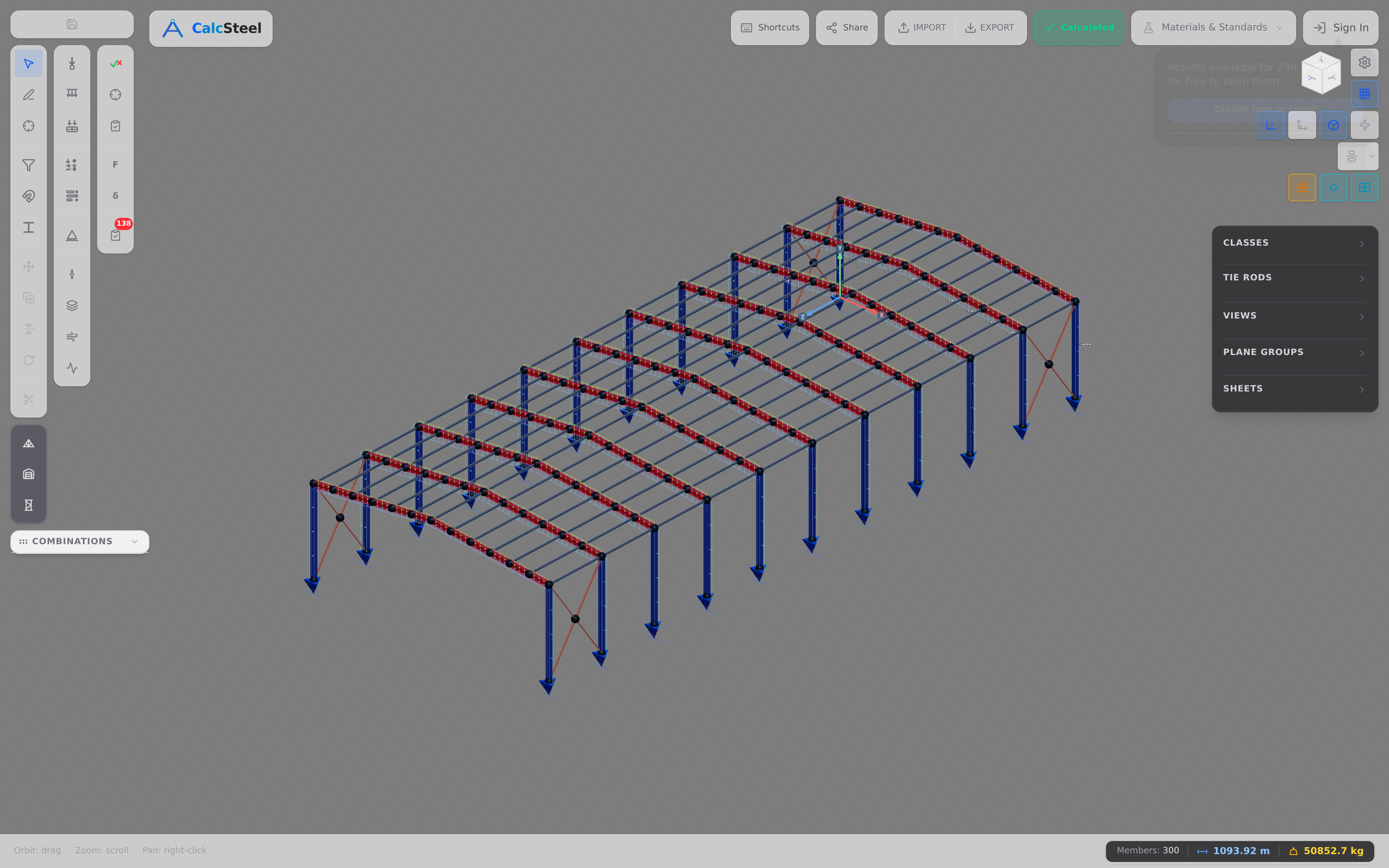
Why Data Centers Are Steel Buildings
In data-center economics, the schedule is king. Goldman Sachs Research expects data-center power demand to rise about 50% to ~92 GW by 2027 — and every week a hall sits unfinished is a week of unsold compute on hardware that is already depreciating. Steel wins this race for reasons that are structural, not sentimental:
- Speed to power. A steel frame is fabricated in the shop while the site is still moving earth. Columns, beams and trusses arrive as finished components and bolt together in a sequence measured in days per bay. When your revenue clock starts at energization, the frame that erects fastest is the frame you build. (This is the same schedule logic driving the wider market — see our deep dive on steel construction trends for 2026.)
- Long clear spans over the white space. Racks, hot/cold-aisle containment and cable pathways want uninterrupted floor plates. A column in the middle of a data hall is a column in the middle of your rack layout forever. Steel portal frames and trusses deliver the 20 m-plus column-free spans a hall demands — we design one at 24 m later in this guide.
- Prefabrication fits the labor reality. Industry surveys report contractor capacity tight or overstretched in over 70% of data-center markets, with labor shortages the top cost driver (Data Center Knowledge). Off-site fabrication moves the man-hours from a scarce site crew to a productive shop — the core argument of modular steel construction, and nowhere does it apply harder than here.
- Change tolerance for density upgrades. AI hardware refreshes are brutal: the racks you design for today will be replaced by heavier ones. A steel frame can be reinforced, re-supported and re-analyzed member by member. Strengthening a beam is a weekend of welding; strengthening a concrete slab is a demolition conversation.
- Non-combustible by nature. Steel doesn't burn and doesn't feed a fire — a baseline requirement when the building's contents are worth orders of magnitude more than the building, and the fire-protection strategy (detection, suppression, compartmentation) is engineered around a frame that stays predictable.
None of this is unique to one hyperscaler or one region — it is why the data-center segment has become one of structural steel's fastest-growing customers. But 'it's a steel building' is only the first sentence of the story. What kind of steel building? That's the anatomy question, and it's next.
The Structural Anatomy of a Data Hall
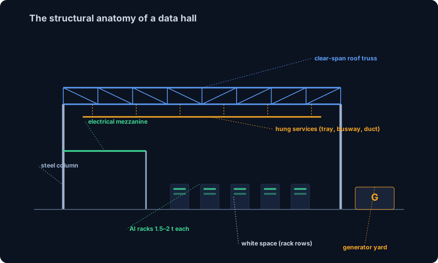
Strip away the cladding and a data center is a small family of steel structures doing very different jobs. Understanding who carries what is the fastest way to understand where the tonnage — and the engineering risk — actually lives.
The shell: portal frames or trusses over the hall
The primary structure is a series of transverse frames — either rigid portal frames or trussed roofs on columns — repeating along the building at a regular bay spacing. Their one non-negotiable job: span the full width of the white space with no interior columns, so the rack layout answers to the IT plan, not the structure. Later in this guide we attempt a 24 m span both ways — with a rolled rafter and with a truss — and let the FEM engine referee.
The white-space floor
Under the racks sits the most heavily loaded 'office floor' you will ever design: a slab on steel floor beams, sized for rack rows, containment aisles and the maintenance traffic between them. This is where the loads get genuinely unusual — the next section puts numbers on it, and Worked Example 1 designs an actual rack-floor beam.
Electrical and mechanical mezzanines
Switchgear, UPS systems, battery rooms and air handlers frequently live on steel mezzanines stacked beside or above the hall. These are heavy, vibration-conscious platforms in their own right — often carrying equipment loads well beyond anything in the hall itself — and they lean on the same frame.
The roof that carries the building's services
Here is the detail newcomers miss: in a data hall, the roof structure is not just keeping rain out. Cable tray, busway, ductwork, piping and containment systems hang from the roof steel. Every rafter or truss bottom chord doubles as a utility spine, and those hung services add real, permanent load along the entire span. Design the roof for the weather and you have designed half the roof.
Equipment yards and generator pads
Outside the envelope, generators, transformers and chillers sit on their own foundations and pads — discrete, very heavy objects whose supports, access steel and screening connect back into the structural package.
Security and screen walls
Perimeter screen walls, security barriers and acoustic screens round out the steel scope. Individually minor, collectively a real line item on a campus measured in thousands of tonnes.
Every one of these structures is sized by its loads — and data-center loads are like nothing in a conventional building. That deserves its own section.
Data-Center Loads: Nothing Like an Office
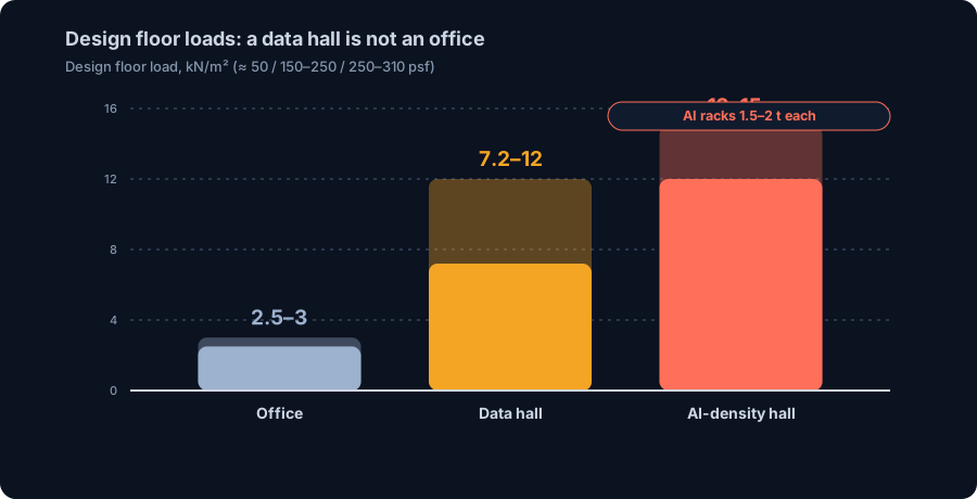
What is a design floor load? A design floor load is the weight per square metre a floor must safely support — equipment, people, cabling and an allowance for the future — expressed in kN/m² (or psf). Every beam, column and connection beneath that floor is sized around this single number, so choosing it well is the whole game.
Now put data-center numbers next to that definition and the problem snaps into focus:
- Offices: typically 2.4–3 kN/m² — the familiar 50 psf class that most floor-framing intuition is calibrated to.
- Modern data halls: commonly published at 7.2–12 kN/m² (150–250 psf) — already three to four times the office figure.
- AI-density halls: trending to 12–15+ kN/m² as liquid-cooled, GPU-dense racks arrive. Individual AI racks commonly weigh 1.5–2 tonnes each today, and vendor roadmaps point beyond 3 tonnes.
In other words: an AI hall floor can carry four to five times the design load of the office building next door — and unlike an office, where the load is a statistical crowd of people and furniture, here it is real, permanent, parked hardware. Rows of 1.5–2 t point loads marching down the aisles, present on day one and heavier at every refresh.
And the floor is only half the load story:
- Hung services along the roof. As the anatomy section showed, busway, cable tray, ducting and piping hang from the roof steel — and they add real permanent load along every span, part of the full 15 kN/m we carry in the roof examples later. It is a large reason the 'simple' roof turns out not to be simple.
- Generators and transformers as heavy point loads. Standby generation and power distribution equipment arrive as discrete multi-tonne objects. Whether on grade or on mezzanines, their supports are designed around concentrated loads, not area loads.
- Vibration sensitivity. IT equipment — especially spinning media and precision cooling — is sensitive to floor vibration in a way office occupants never are. That pushes data-hall design past 'strong enough' into 'stiff enough', with deflection and dynamic behavior taking the governing role. Hold that thought: in the worked examples ahead, stiffness — not strength — decides every single member size. If that theme interests you, we go deeper in serviceability, deflection and vibration in steel design.
Enough context. Let's put a beam under a row of AI racks and run the real numbers.
Worked example 1: a floor beam under AI racks
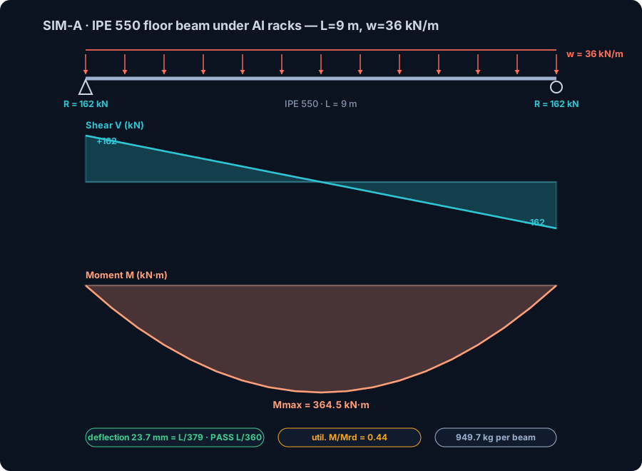
Enough context — let's size real steel. The setup is a typical AI data-hall floor bay: beams spanning 9 m, spaced 3 m apart, carrying a design floor load of 12 kN/m² (the 250 psf end of the published data-hall range). We ran the full analysis in CalcSteel's FEM engine, and every number below comes straight from it — validated against closed-form theory.
Step 1 — from area load to line load
Each beam collects the load from half the spacing on either side — its tributary width of 3 m:
- w = q × tributary width = 12 kN/m² × 3 m = 36 kN/m
That's 36 kN on every metre of beam — more than a heavy AI rack's worth of weight on every metre, before the racks even roll in. Compare that with an office beam at the same spacing, which would carry just 9 kN/m.
Step 2 — reactions and internal forces
For a simply supported beam under uniform load, the engine reports:
- Reactions: R = 162 kN at each end (= wL/2 = 36 × 9 / 2 — exact).
- Shear diagram: Vmax = 162 kN at the supports, crossing zero at midspan.
- Bending moment: Mmax = 364.5 kN·m at midspan — exactly wL²/8, which is the closed-form check the FEM result matches to the decimal.
If you want the theory behind those diagrams, our pillar on shear force and bending moment diagrams builds them from first principles.
Step 3 — pick a section and check strength
We chose an IPE 550 in S355/A992-class steel (fy = 355 MPa, E = 200 GPa). At 105.52 kg/m, the 9 m beam weighs 949.7 kg — knocking on a tonne of steel for a single floor beam. Its elastic moment capacity is Mrd = 836.8 kN·m, so:
- Utilization = 364.5 / 836.8 = 0.44
Only 44% of the strength is used. By strength alone this beam looks wildly oversized — you might be tempted to drop two or three sections. Don't. Yet.
Step 4 — the check that actually governs: deflection
The engine computes a midspan deflection of 23.7 mm, which is L/379 over the 9 m span. The usual floor limit is L/360 (25 mm here), so the IPE 550 passes — but barely, with about 5% of stiffness margin against a 56% strength margin.
That asymmetry is the single most important lesson in data-center floor design: under rack-density loads, stiffness governs, not strength. A lighter section would still carry the moment comfortably and fail the deflection check outright. In a hall full of vibration-sensitive IT gear, raised-access floors and rigid busway runs, that deflection limit is not bureaucracy — it's what keeps the white space serviceable. More on beam capacity checks in our guide to steel beam load capacity.
Office floor vs AI floor: same bay, different beast
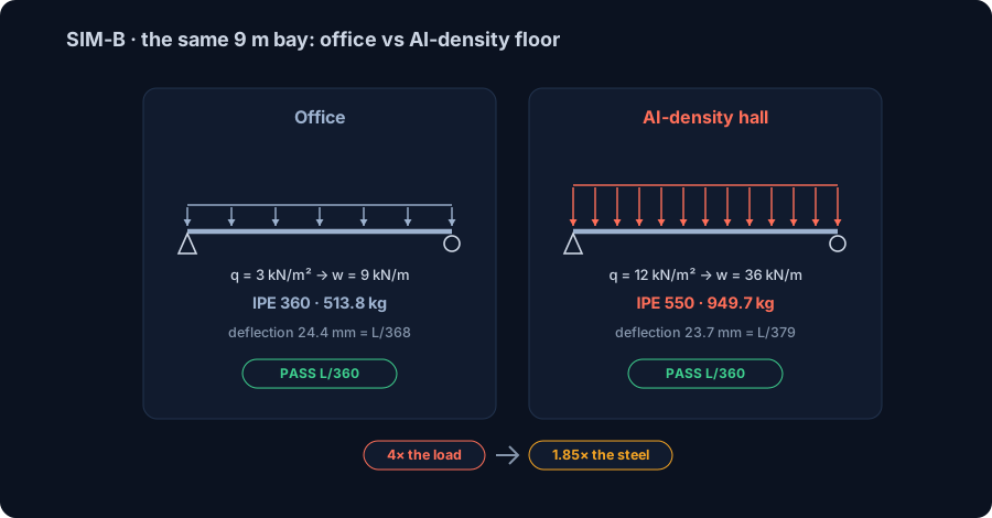
Here's a question every owner asks when a conventional building is floated for conversion: how much more steel does an AI hall really need? To answer it honestly, we kept everything identical — same 9 m span, same 3 m beam spacing, same S355-class steel, same L/360 limit — and changed only the design floor load. One bay as an office, one as an AI hall.
The office bay: 3 kN/m²
An office floor at 3 kN/m² (the 50 psf class) puts w = 9 kN/m on each beam. The engine right-sizes that to an IPE 360 at 57.09 kg/m:
- Mmax = 91.1 kN·m, utilization 0.29
- Deflection 24.4 mm = L/368 → passes L/360
- Beam mass: 513.8 kg
The AI bay: 12 kN/m²
Swap in the AI-density load of 12 kN/m² (w = 36 kN/m) and the bay needs the IPE 550 from Worked Example 1: Mmax = 364.5 kN·m, utilization 0.44, deflection 23.7 mm = L/379, mass 949.7 kg.
4× the load, 1.85× the steel
Notice the ratio: the load quadrupled, but the steel per beam grew only 1.85× (513.8 kg → 949.7 kg). Why isn't it 4×? Because deflection governs both bays — look at how close both results sit to the limit: L/368 for the office, L/379 for the AI hall, while strength utilization idles at 0.29 and 0.44. When stiffness rules, going deeper (IPE 360 → IPE 550) buys second-moment-of-area far faster than it adds kilograms. Depth is cheap stiffness — a theme that returns with a vengeance when we get to the roof.
There's a warning hiding in the same numbers, though. Across a whole hall, that 1.85× multiplies over every beam in the white space — a structural premium that scales into serious tonnage on a hyperscale campus that can absorb up to about 20,000 tons of structural steel (Zekelman Industries, via Fastmarkets). And it cuts the other way too: an office building "converted" to a data hall without touching the frame is carrying 4× the load on beams sized — and stiffness-checked — for a quarter of it. That's why serviceability, not strength, is the first conversation in any data-center structural brief.
Size your own floor beam — live
You don't have to take our diagrams on faith. The interactive beam calculator mounted right below runs the same closed-form mechanics we validated the FEM engine against — free, unlimited, and no login needed for the math.
Try reproducing Worked Example 1 yourself. The recipe:
- Section: IPE 550 (S355-class steel)
- Span: 9 m, simply supported
- Uniform load: 36 kN/m (that's 12 kN/m² of AI-hall floor load × 3 m tributary width)
Watch the results appear as you type: reactions of 162 kN at each end, the shear diagram peaking at the supports, the moment diagram cresting at 364.5 kN·m midspan, and a deflection of 23.7 mm = L/379 — just squeezing past the L/360 floor limit.
Then break it on purpose. Drop to an IPE 450 and watch deflection fail while strength still passes — the whole stiffness-governs story of this article, live in front of you. Stretch the span, thin out the load to the 9 kN/m office case, swap sections until you feel where the limits bite. That intuition is the point.
Prefer a full page with more options and saved states? The same tool lives at the CalcSteel beam calculator. And when a single beam stops being enough — continuous spans, frames, the roof trusses coming up next — the complete CalcSteel editor — a real 3D FEM engine in the browser — is available on a genuinely free plan (and free for students).
Max moment
45 kN·m
Max shear
30 kN
Max deflection
10.55 mm
= L/569
Bending stress σ
84.4 MPa
σ = M/Sx
Utilization
44.0%
NBR 8800 · δ ≤ L/250
Geometry & supports
Section
Ix 7999 cm⁴ · Sx 533 cm³ · 42.2 kg/m
Point loads (↓ positive)
None — add as many as you need.
Distributed loads (uniform or trapezoidal)
Model sketch
Diagrams — free PNG / SVG / CSV export, no watermark
Step-by-step — the calculation memory of YOUR beam
IPE 300 · L = 6 m · fy = 250 MPa
1. Reactions (equilibrium of the solved FEM model)
ΣFy = 0 · ΣM = 0
R_A = 30 kN · R_B = 30 kN
2. Peak shear (read from the SFD)
Vmax = |V(x)|max
Vmax = -30 kN @ x = 6 m
3. Peak moment (read from the BMD)
Mmax = |M(x)|max
Mmax = 45 kN·m @ x = 3 m
4. Peak deflection
EI = 15998 kN·m² (E = 200 GPa)
δmax = 10.55 mm @ x = 3 m = L/569
5. Elastic bending stress
σ = Mmax / Sx = 45.00 × 10³ / 533.3
σ = 84.4 MPa
6. Bending check — both codes, side by side
NBR 8800: σ ≤ fy/1.10 = 227.3 MPa · AISC 360: σ ≤ 0.90·fy = 225 MPa
NBR 37.1% PASS · AISC 37.5% PASS
7. Deflection check (serviceability — code-independent)
δ ≤ L/250 = 24 mm
10.55 mm / 24 mm = 44.0% PASS
Recomputed live from the current inputs by the direct-stiffness FEM engine — change any load and every step updates. Reproduce it by hand with the formulas in the sections below.
Lightest catalog profiles that pass (974 flexural candidates · NBR 8800)
| Profile | Std | Weight | Total steel | σ util | δ util | |
|---|---|---|---|---|---|---|
| W310x21 | AISC | 21 kg/m | 126 kg | 83% | 98% | |
| VS 300x23 | BR | 22.6 kg/m | 136 kg | 71% | 84% | |
| U 300x90x6.3 | BR | 23.1 kg/m | 139 kg | 82% | 98% | |
| U 300x100x6.3 | BR | 24.1 kg/m | 145 kg | 77% | 91% | |
| VS 250x25 | BR | 24.6 kg/m | 148 kg | 70% | 100% |
Elastic bending (σ = M/Sx vs fy/γa1, γa1 = 1.10 — NBR 8800) + deflection screening of the full flexural catalog. Lateral-torsional buckling, shear and local buckling are NOT checked here — run the full NBR 8800 / AISC 360 verification in the 3D editor.
The roof problem: 24 m over the white space
Down at floor level the story was about load. Up at the roof, the story is about span. A data hall earns its keep as uninterrupted white space: rack rows, hot/cold-aisle containment, and overhead busway all want a ceiling with no columns in the middle of it. A column in the wrong place doesn't just cost one rack position — it breaks the airflow geometry and the power distribution layout of the entire row. So the roof structure over the hall routinely has to clear 20 m or more in one shot, while also carrying the services hung beneath it.
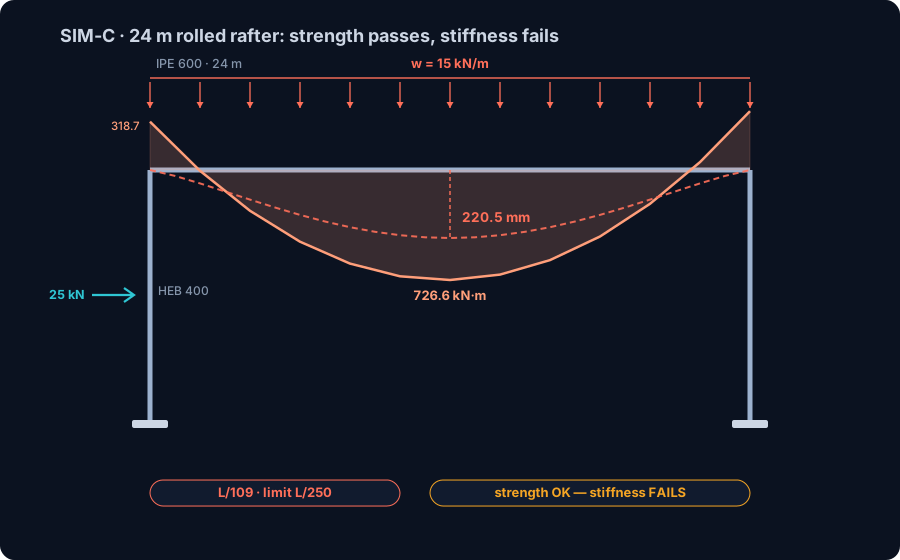
Let's try the obvious first move: a portal frame with a rolled rafter, the workhorse of industrial steel (we cover the type in depth in our portal frame design guide). We modelled it in the CalcSteel FEM engine — and this one needs FEM, because a sway frame with fixed bases is statically indeterminate; no hand formula gives you the real moment distribution.
- Geometry: 24 m clear span, 6 m eave height, fixed bases.
- Members: HEB 400 columns, IPE 600 rafter (122.45 kg/m).
- Loads: roof plus hung services at w = 15 kN/m on the rafter, plus a 25 kN lateral wind load.
The engine's equilibrium check closes exactly — ΣFx = −25 kN against the wind, ΣFy = 360 kN against the gravity load — and the frame action shows up immediately in the moment diagram. The rafter peaks at Mmax = 726.6 kN·m at midspan, but the windward knee picks up 318.7 kN·m and its fixed base carries −135.7 kN·m. That redistribution is the whole point of a portal frame: the columns relieve the rafter. On strength, the IPE 600 is fine.
Then comes the deflection check, and the wheels come off. Midspan deflection is 220.5 mm — L/109. The roof limit of L/250 allows just 96 mm. That's not a marginal fail; the frame is more than twice too flexible, with 4.80 t of steel in it (2.94 t in the rafter alone). The lesson generalizes: at data-hall spans, a rolled rafter runs out of stiffness long before it runs out of strength. Throwing a heavier section at it is the expensive way to lose slowly. There's a smarter fix.
The fix: a roof truss — same steel, 4.7× stiffer
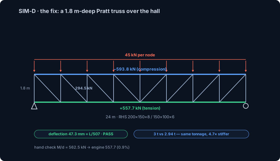
The portal frame failed because a rolled section 600 mm deep is simply too shallow for a 24 m span. Stiffness scales with the square of structural depth — so instead of buying a heavier rafter, we buy depth. Enter the Pratt roof truss.
- Geometry: 24 m span, 1.8 m deep, 8 panels of 3 m, simply supported.
- Chords: RHS 200×150×8 (41.92 kg/m). Web members: RHS 150×100×6 (22.45 kg/m), welded joints.
- Loads: the same 15 kN/m of roof plus hung services, applied as 45 kN loads at the top-chord panel points.
The engine returns reactions of R = 180 kN at each support — exact, as symmetry demands. The force pattern is classic truss behaviour: the bottom chord goes into tension, peaking at +557.7 kN at the mid-panels; the top chord takes −593.8 kN of compression; the end diagonals carry 294.5 kN down to the supports.
Here's the part we love: you can check the FEM engine by hand. Cut the truss at the panel next to midspan and take moments about the top-chord node at 9 m — the method of sections. The moment there is 180×9 − 22.5×9 − 45×6 − 45×3 (those last two are the panel loads at 3 m and 6 m, with their lever arms) = 1012.5 kN·m, and dividing by the 1.8 m depth gives a bottom-chord force of 562.5 kN. The engine says 557.7 kN — a 0.9% difference, explained by the welded joints: the real truss behaves as a rigid-jointed frame with a whisper of secondary bending, which pure pin-jointed statics ignores. When your software and your hand calc disagree by less than 1% for a reason you can name, you can trust both.
And the deflection? 47.3 mm = L/507 — sailing past the L/250 limit with room to spare. Now compare the bill of materials: the whole truss weighs 3.00 t, against 2.94 t for the failed IPE 600 rafter alone. Essentially the same tonnage, 4.7× stiffer. That is the single most useful principle in long-span roof design: depth buys stiffness; weight doesn't. The truss puts its material 1.8 m apart instead of 600 mm apart, and geometry does the rest. For the full theory — panel layouts, chord sizing, when Pratt beats Warren — see our steel truss design guide.
One honest caveat before you run off and weld one: the chord-force check above is necessary, not sufficient. The compression chord must still be verified for buckling, and the welded joints for their own resistance — we flag both in the checklist below.
Serviceability rules the data hall
Step back and look at every worked example in this guide. Not one of them was decided by strength. The rack-floor beam sat at 0.44 utilization — 56% of its bending capacity unused — and still only just cleared its deflection check at L/379 against L/360. The office beam passed at L/368 with utilization 0.29. The portal frame had strength to spare and failed spectacularly at L/109. The truss won on stiffness, at L/507. In a data center, serviceability is the design; strength is usually along for the ride.
Why are the limits so unforgiving here? Because almost everything in the building is attached to the structure and cares how much it moves:
- Hung services. Busway, cable tray, and ducting hang from the roof steel in long, continuous runs. Busway joints and tray splices have tight tolerance on relative movement — a roof sagging 220 mm over 24 m isn't a structural failure, but it can be an electrical-distribution problem.
- Rack rows and containment. Hot/cold-aisle containment panels, doors, and ceiling baffles are built plumb and square. Excessive floor or roof deflection racks the enclosure, opens air leaks, and degrades the very airflow separation the hall depends on.
- The racks themselves. Rows of 1.5–2 t cabinets sit on that floor. Differential deflection between adjacent bays shows up as tilt across a row.
- Vibration-sensitive IT gear. Spinning media and precision hardware dislike floor vibration, so data-hall floors are pushed toward stiffer, higher-frequency designs than an office would ever need. Stiffness against static deflection and stiffness against perceptible vibration are two faces of the same coin.
The working limits we used are the common published ones: L/360 for floors and L/250 for roofs — and mission-critical owners frequently specify stricter. Our numbers show how tight the game really is: the IPE 550 floor beam passed with about 5% of margin (L/379 vs L/360), and the roof needed a change of structural system, not a bigger section, to get from L/109 to L/507. If you sized either member on strength alone, you'd have shipped a failure.
This is exactly why we run every check, every time. In the CalcSteel editor, the verification view paints each member by its governing check — and in data-center work you'll watch the deflection color govern long before the stress color does. For the deeper theory — deflection limits by occupancy, natural frequency, and when vibration governs outright — read our companion pillar on serviceability, deflection and vibration.
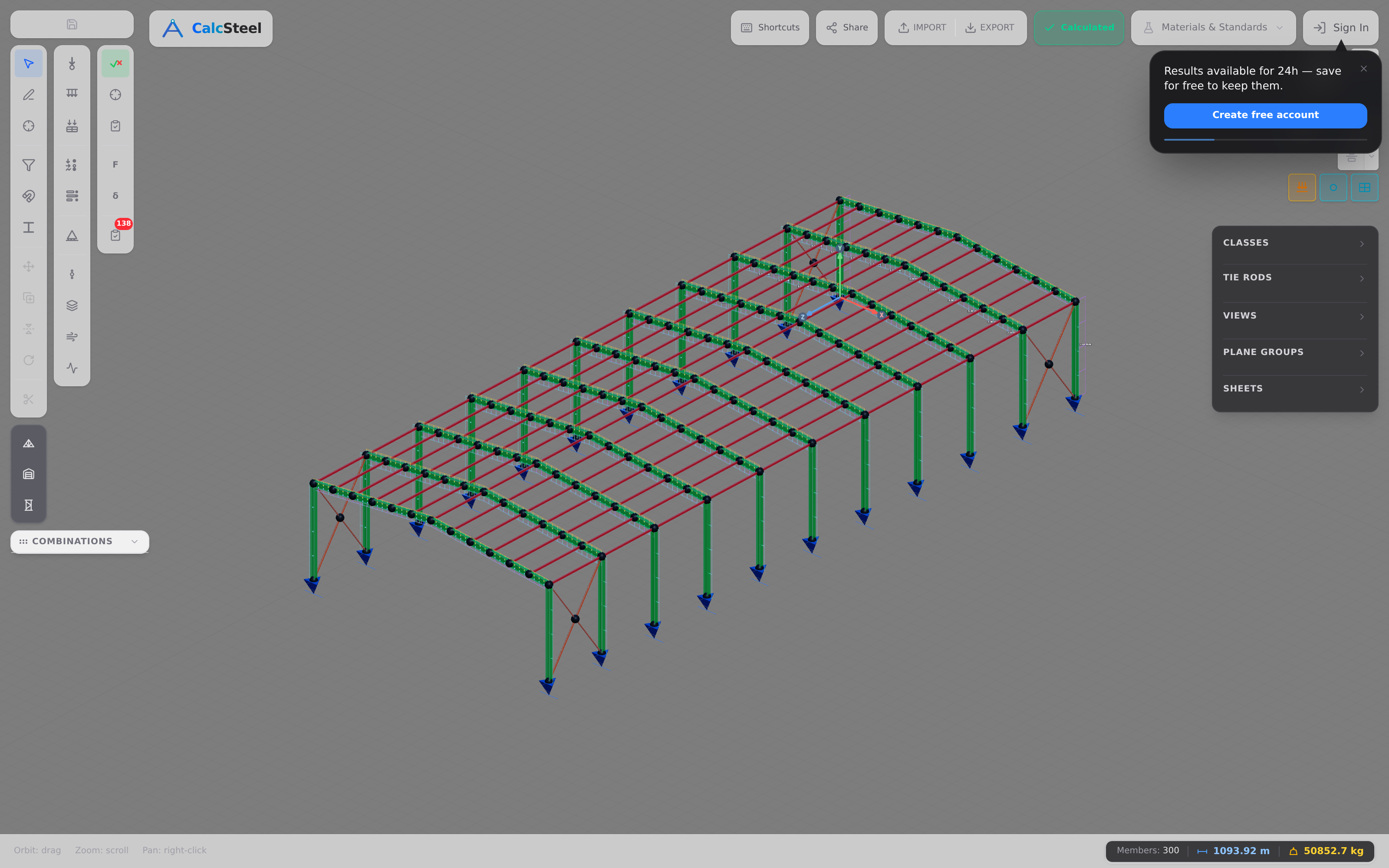
Built at the speed of the AI race
In a data-center pro forma, the structure is not the expensive part — the time is. Every week a hall sits unfinished is a week of unsold compute, which is why the industry's real design driver in 2026 is schedule compression. And the numbers behind that pressure are staggering: Dodge data reported by Equipment World puts US data-center construction starts at about $77.7 billion in 2025 — roughly +190% year over year — while UBS projects global AI infrastructure spending around $500 billion in 2026, up from roughly $375 billion in 2025. Goldman Sachs Research expects data-center power demand to rise about 50% to ~92 GW by 2027. The buildings have to keep pace with the chips.
Steel is winning this race for a structural reason and a logistical one. Structurally, the frames we sized in the worked examples — floor beams, portal columns, roof trusses — are repetitive, predictable, and bolt together in any weather. Logistically, they can be fabricated off-site, in parallel with earthworks and utility runs, then erected in days per bay. That matters enormously right now: industry surveys reported by Data Center Knowledge find contractor capacity tight or overstretched in over 70% of data-center markets, with labor shortages the top cost driver. Prefabrication moves person-hours from a scarce, expensive site crew to a controlled shop — the same logic we unpack in our modular steel construction guide.
The scale per project reshapes the supply chain too. A single hyperscale campus can take up to about 20,000 tons of structural steel (Zekelman Industries, via Fastmarkets). Orders that size get placed against mill schedules months ahead, which rewards teams who freeze the structural scheme early — and punishes redesigns. This is another reason the stiffness lessons from the portal-frame and truss examples matter: discovering at 60% design that your rolled rafter fails L/250 is a mill-order problem, not just a drawing problem.
Finally, hyperscalers carry public ESG commitments, and at 20,000 tons per campus the embodied carbon of the frame is a line item their sustainability teams actually read. Specifying lower-carbon steel — recycled-content EAF product or green-hydrogen routes — changes the footprint of the structure without changing a single member size, because green steel is metallurgically the same steel. We cover the numbers, the procurement language, and the right-sizing lever in depth in our green and low-carbon steel guide; for the broader market picture, see steel construction trends for 2026.
Common mistakes & FAQ
After running these simulations, a pattern emerges: almost every mistake in data-center steel design comes from importing office-building instincts into a mission-critical building. Here is the checklist we would pin above the desk.
Six mistakes to avoid
- Sizing floor beams by strength alone. Our IPE 550 under AI-rack loading sat at a comfortable 0.44 utilization in bending — and still only just passed deflection at L/379 vs L/360. In a data hall, stiffness governs; a strength-only check will hand you an undersized beam that passes on paper and bounces in service.
- Ignoring the hung services. Busway, cable tray, and ducting are carried by the roof steel, and in the portal-frame example those hung services were part of the full 15 kN/m on the rafter. Design the bare roof and you will meet the MEP contractor with no capacity left.
- Assuming office deflection limits are enough. An office designer might accept a livelier roof; over containment aisles and rigid busway joints, L/250 on roofs and L/360 on floors are the practical floor, not the ceiling — see our serviceability deep-dive.
- Forgetting vibration. IT equipment is vibration-sensitive. A floor that passes static deflection can still transmit footfall and mechanical vibration into rack rows; treat the static check as necessary, never sufficient.
- Treating the truss chord check as the whole check. In the truss example the top chord carries 593.8 kN of compression — that member lives or dies by buckling, and the welded joints by connection design, neither of which appears in a bare axial-force printout. Chord forces are the start of the verification, not the end; our truss design guide walks the full sequence.
- Designing for today's racks only. AI racks commonly weigh 1.5–2 t each today, with vendor roadmaps pushing beyond 3 t. A floor sized tightly to the current fit-out becomes the constraint on the next hardware refresh — and Worked Example 1's beam, at 0.44 strength utilization, shows how deflection-governed designs often carry hidden strength margin worth planning around.
How much structural steel is in a data center?
It scales with the campus, but the benchmark figure is striking: a single hyperscale campus can take up to about 20,000 tons of structural steel (Zekelman Industries, via Fastmarkets). That covers the hall shells, mezzanines, roof framing that carries the building services, and equipment-yard structures.
What floor load should I use for AI racks?
Modern data halls are commonly published at 7.2–12 kN/m² (150–250 psf), and AI-density halls are trending to 12–15+ kN/m² — a long way from the 2.4–3 kN/m² office class. Our worked example used 12 kN/m² over a 3 m tributary width, giving 36 kN/m on the beam. Always confirm the fit-out density with the operator; racks of 1.5–2 t each, and climbing, are the load that sets it.
Why do data halls use roof trusses instead of beams?
Because depth buys stiffness and weight does not. Our FEM comparison made it concrete: a rolled IPE 600 rafter over a 24 m hall deflected 220.5 mm = L/109 — a hard fail against L/250 — while a 1.8 m-deep Pratt truss of almost identical tonnage (3.00 t vs 2.94 t) deflected 47.3 mm = L/507. Same steel, 4.7× stiffer, purely from geometry.
Can I check these numbers myself for free?
Yes — that is the point of this guide. The embedded beam calculator reproduces the floor-beam example with no login, and CalcSteel's free plan gives you the browser-based FEM editor for frames and trusses like these. Students get free access through the education program. No card, no countdown — run the model, question the numbers, keep the margin.
Key takeaways
The AI build-out is the biggest steel story of 2026, but under the headlines it is still statics — done to a stricter standard. Five things to carry out of this guide:
- Data-center loads are a different species. AI halls at 12–15+ kN/m² versus 2.4–3 kN/m² for offices, racks of 1.5–2 t and climbing, plus services hung from the roof steel. Start every member from the real load path, not a lookup habit.
- Stiffness governs, not strength. Our AI-floor IPE 550 used only 44% of its bending capacity yet barely passed L/360; four times the office load bought 1.85× the steel because deflection drove both designs.
- At data-hall spans, rolled sections run out of stiffness first. The 24 m IPE 600 rafter was fine in bending and catastrophic in deflection at L/109.
- Depth is the cheapest stiffness there is. A 1.8 m Pratt truss matched the failed rafter's tonnage — 3.00 t vs 2.94 t — and came out 4.7× stiffer at L/507. Buy geometry before you buy kilograms.
- Schedule is the real client. With $77.7B in US starts, ~20,000 tons per hyperscale campus, and contractor capacity strained in over 70% of markets, prefab-friendly, early-frozen steel schemes are what keep halls on the energization date.
Now make the numbers yours. Rerun the floor beam in the free beam calculator — IPE 550, 9 m, 36 kN/m — and watch the reactions, diagrams, and deflection land on the values in this guide. When you are ready for the frames and trusses, CalcSteel's free plan puts a real FEM engine in your browser, and students build at no cost through the education program. The next 20,000-ton campus will be designed by engineers who trust their numbers because they can check them.
Sources
- 1.Fastmarkets — US steelmakers see 'robust opportunity' in data center expansion (Zekelman)
- 2.Equipment World — Data center construction boom to grow in 2026 (Dodge data)
- 3.Data Center Knowledge — AI Data Center Boom Strains Global Construction Capacity
- 4.EN 1993-1-1 — Eurocode 3: Design of steel structures
- 5.AISC 360 — Specification for Structural Steel Buildings
Try CalcSteel for free
Model, analyze and design steel structures in your browser. No install, no signup.
Open the 3D editor