Portal Frame Design: Types, Analysis & Sizing
Learn how to design steel portal frames for warehouses and industrial buildings. Covers frame types, haunched connections, wind load effects, and member sizing.
Key takeaways
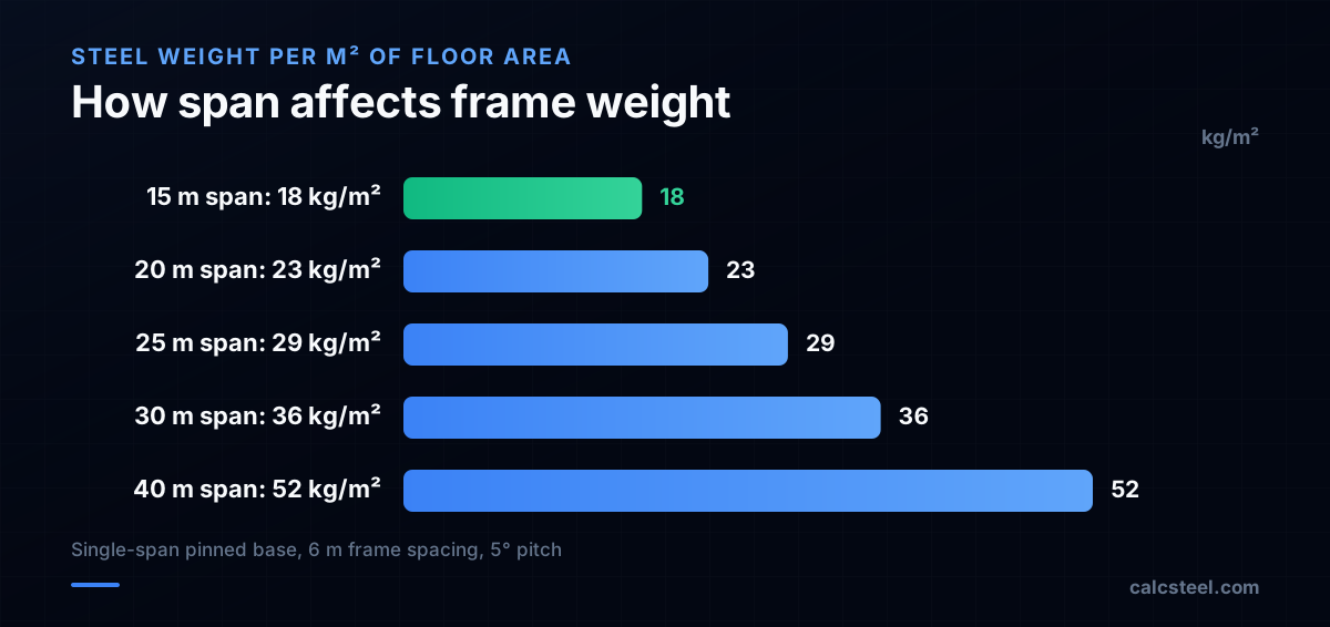
- Portal frames are the most economical system for single-story steel buildings, giving clear spans of 15–50 m without internal columns.
- The bending moment peaks at the eave (knee), so a haunch is added there — saving 15–30% of rafter weight versus a prismatic rafter.
- Rafters and columns are sized as beam-columns using the AISC 360 Chapter H interaction check, with unbraced lengths set by purlin and girt spacing.
- P-Δ (second-order) effects and lateral-torsional buckling of the bottom flange near the knee govern stability; fly bracing and an eave strut are essential.
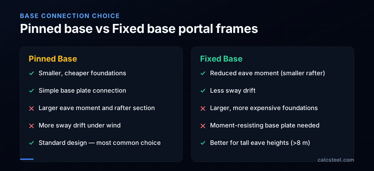
- Pinned bases give cheaper foundations but larger eave moments; fixed bases cut sway drift at the cost of larger, moment-resisting foundations.
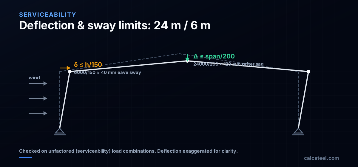
- Serviceability often decides the frame before strength does: eave sway (≈ h/150) and rafter deflection (≈ span/200) under unfactored loads are what push a design from a pinned base toward a fixed base.
- A plastic collapse (mechanism) analysis can size a portal frame about 10% lighter than an elastic design, because the frame redistributes moment after the first hinge forms. It is valid only for compact (Class 1) sections with laterally restrained compression flanges.
What is a portal frame and why is it so common?
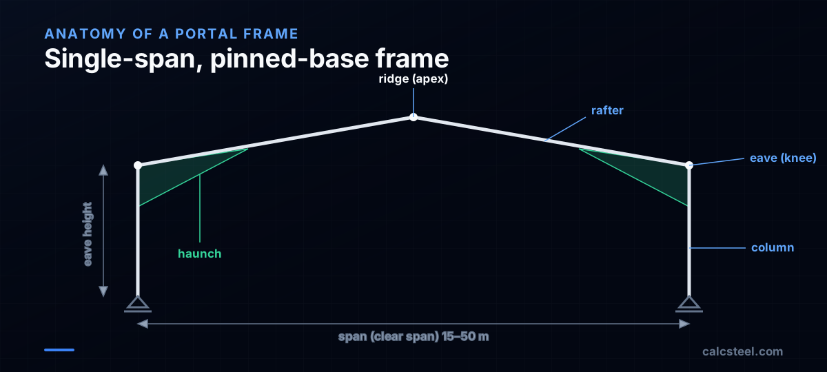
A portal frame is a rigid, single-story structural frame consisting of columns and a pitched or flat rafter connected by moment-resisting joints at the eaves (knees). It is the most common structural system for single-story steel buildings worldwide — warehouses, factories, sports halls, retail stores, and aircraft hangars.
Portal frames are popular because they:
- Provide large clear spans (15–50 m) without internal columns
- Use standard hot-rolled sections (IPE, HEA, W-shapes)
- Are straightforward to analyze, fabricate, and erect
- Allow flexible internal layouts that can change over the building's life
The frame works as a rigid ring: lateral loads (wind) create bending moments that are shared between the rafter and columns. The knee connection is the most stressed point in the frame, which is why it is often reinforced with a haunch — a deepened section that increases the moment capacity at the critical location.
What are the main types of steel portal frames?
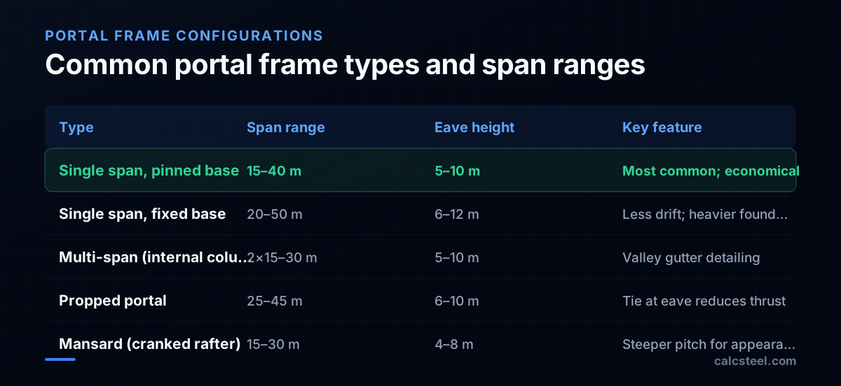
Single-span, pinned base
The standard configuration. Columns are pinned at the base (no moment transfer to foundation). The rafter spans the full width with a ridge at the center. This is the most economical frame for spans up to 35 m.
Single-span, fixed base
Column bases are moment-connected to the foundation. This reduces the eave moment and rafter weight but increases foundation size and cost. Fixed bases are used when eave height is large (>8 m) or when sway must be limited.
Multi-span
Two or more spans with internal columns. Each span acts as a separate portal frame sharing the internal column. Valley gutters between spans need careful detailing to prevent water ponding.
Propped portal
A horizontal tie connects the eave knees, absorbing the horizontal thrust. This allows lighter columns but adds an obstruction across the building interior. Used for very wide spans where column sizes become impractical.
Mono-pitch (lean-to)
A single rafter slopes in one direction, supported on a tall back wall and a shorter front wall. Common for extensions to existing buildings or where one-directional drainage is needed.
How do you analyze a portal frame for gravity and wind loads?
Portal frame analysis determines the bending moment diagram (BMD) under each load case. The key load cases are:
Gravity loads (dead + live/snow)
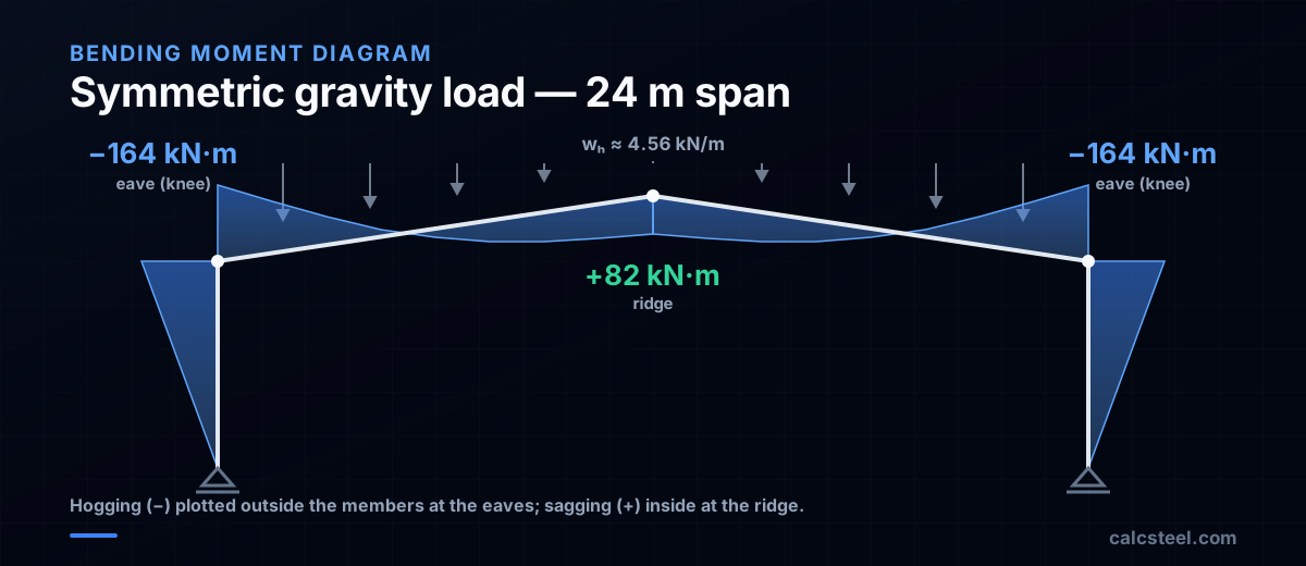
- Create a symmetric BMD with maximum negative moment at the eaves and maximum positive moment near the ridge
- The eave moment is approximately M_eave ≈ −wL²/16 for pinned base (varies with pitch and stiffness ratios)
- The ridge moment is approximately M_ridge ≈ +wL²/32
Wind loads (lateral + uplift)
- Wind on the windward wall and roof creates pressure + suction distributions
- The resulting BMD is antisymmetric: one knee gets larger moment than the other
- Wind uplift can reverse the moment in the rafter, putting the bottom flange in compression
- The net uplift combination (0.9D + 1.0W) often governs connection design at the ridge and base
Analysis method
For preliminary design, approximate formulas give reasonable estimates. For final design, use a structural analysis program (CalcSteel, for example) that performs:
- Second-order elastic analysis (P-Δ effects are significant in slender portal frames)
- All load combinations per ASCE 7 or the relevant national code
- In-plane and out-of-plane stability checks
Example — 24 m span, 6 m eave, 5° pitch
- Dead load: 0.3 kN/m² × 6 m frame spacing = 1.8 kN/m on rafter
- Live load: 0.25 kN/m² × 6 = 1.5 kN/m
- Wind: computed per ASCE 7 or NBR 6123
Factored gravity: w_u = 1.2(1.8) + 1.6(1.5) = 2.16 + 2.40 = 4.56 kN/m
Eave moment (approx): M_eave ≈ 4.56 × 24² / 16 ≈ 164 kN·m
How do you do a plastic collapse analysis of a portal frame?
The elastic analysis above sizes every section for the peak elastic moment. A plastic collapse analysis asks a different question: what load actually collapses the frame? Portal frames are its classic application, because they fail through a clean sequence of plastic hinges rather than a sudden buckle.
The worked frame
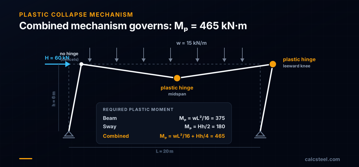
Take a single-span, pinned-base portal with a 20 m span and 6 m eave height, and make the columns and rafter the same section. The factored loads are a gravity line load w_u = 15 kN/m on the rafter and a horizontal wind force H = 60 kN at the windward eave.
Step 1: elastic analysis locates the first hinge
Under gravity alone, CalcSteel's engine returns a knee moment of 416 kN·m and a midspan moment of 334 kN·m. A hand slope-deflection check gives 417 kN·m at the knee, within 0.1%. The peak sits at the eave, so that is where the first plastic hinge forms.
Step 2: the three collapse mechanisms
Once a section is fully yielded it acts as a plastic hinge that rotates at a constant moment M_p. Collapse arrives when enough hinges turn part of the frame into a mechanism. Equating external work to internal work (the virtual-work method) for each candidate gives the plastic moment it needs:
| Mechanism | Plastic hinges | Required M_p |
|---|---|---|
| Beam | Two knees + midspan | wL²/16 = 375 kN·m |
| Sway | Two knees | Hh/2 = 180 kN·m |
| Combined | Leeward knee + midspan | wL²/16 + Hh/4 = 465 kN·m |
The combined mechanism cancels the hinge at the windward knee, where the beam and sway rotations oppose, and needs the largest M_p, so it governs.
Step 3: size for the governing mechanism
The design plastic moment is therefore 465 kN·m (343 kip·ft). A W16×45 in A992 steel provides it almost exactly: with Z_x = 82.3 in³, M_p = f_y·Z_x = 465 kN·m. The engine's factored reactions for this combination, 132 kN and 168 kN vertical at the two bases, match hand statics to the kilonewton and confirm the load path.
Why plastic design saves steel, and when you can use it
For gravity alone the beam mechanism needs only M_p = 375 kN·m, about 10% below the 416 kN·m elastic peak. That gap is the moment the frame redistributes after the first hinge forms, real capacity that an elastic design leaves unused. Two conditions unlock it: the sections must be compact (Class 1), with a shape factor Z_x/S_x ≈ 1.13 for this W-shape, so the hinges can rotate without local buckling; and the compression flange at each hinge must be laterally restrained by fly bracing at the eaves. AISC 360-22 Appendix 1 permits design by inelastic analysis, while Eurocode 3 and the SCI green books treat plastic design as the standard route for portal frames.
CalcSteel runs a second-order elastic analysis with member capacity checks rather than tracing hinge formation, so use the mechanism method as a fast hand-check and to fix a preliminary M_p before you build the model.
What is a haunch and how does it reduce portal frame weight?
A haunch is a deepened section at the knee (eave) connection where the rafter meets the column. It is created by cutting a tapered section from the same beam profile and welding it to the underside of the rafter at the knee.
Why use a haunch?
The bending moment diagram of a portal frame peaks at the eave. Without a haunch, the entire rafter must be sized for this maximum moment — wasting material in the rest of the span where the moment is much smaller.
With a haunch:
- The haunch provides the extra depth (and section modulus) where the moment is highest
- The rafter in the span can be a lighter section sized for the smaller midspan moment
- Weight savings of 15–30% compared to a prismatic rafter
Haunch geometry
- Length: Typically 10–15% of the span (2.4–3.6 m for a 24 m span)
- Depth at knee: 1.5–2.5 times the rafter depth
- Taper: Linear taper from the deep end (at the column face) to the rafter depth
Design checks for the haunch
- Moment capacity — Check the section at the deepest point and at several intermediate sections along the taper. The effective section modulus changes with depth.
- Lateral stability — The haunch compression flange (bottom flange under gravity) needs lateral restraint. Fly bracing from the purlins to the bottom flange is essential.
- Web stability — The tapered web is prone to buckling. Check h/t_w at the deepest section.
- Connection — The haunch-to-column connection must transfer the full moment plus shear. End plate connections with high-strength bolts are standard.
What are the rules of thumb for preliminary portal frame sizing?
Before running any analysis, experienced designers reach for a small set of proportioning rules that land the first section sizes within one serial size of the final answer. They come from decades of built portal frames (AISC Design Guide 7 and SCI guidance) and are the fastest way to start the sizing iteration.
Proportioning rules
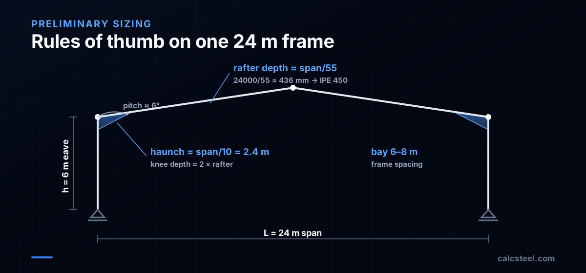
- Rafter depth ≈ span / 55 (range span/50 to span/60). For a 24 m span: 24000 / 55 ≈ 436 mm, so start with an IPE 450.
- Haunch length ≈ span / 10 (about 10% of the span). For 24 m: ≈ 2.4 m.
- Haunch depth below the rafter ≈ rafter depth, for a total depth at the knee of roughly twice the rafter, putting the extra section modulus exactly where the eave moment peaks.
- Column: pick a section whose plastic modulus resists the eave moment. It is rarely lighter than the rafter; wide-flange H-sections (HEA / UC) are popular for their larger minor-axis capacity and simple girt connection.
- Roof pitch ≈ 6° (about 1:10) is the modern economic optimum. Steeper adds cladding area and wind load; flatter risks snap-through and larger deflections.
- Frame spacing ≈ 6–8 m. Wider bays mean fewer frames but heavier purlins and girts.
Checking the 24 m example
Applying the rules to the worked frame: rafter span/55 = 436 mm → IPE 450 (depth 450 mm); haunch span/10 = 2.4 m; total knee depth ≈ 900 mm ≈ 2 × 450. These are the same proportions dimensioned in detail in the next section, proof that the rules put you within one iteration of the final answer.
Caveat: rules of thumb size for gravity. Always confirm with a second-order analysis under the full load combinations, because wind uplift, not gravity, frequently governs the rafter and the holding-down bolts.
How do you size the columns and rafter of a portal frame?
Member sizing follows the beam-column interaction check (AISC H1) because both the rafter and columns carry combined axial force and bending moment.
Rafter sizing
The rafter is primarily a beam with small axial compression from the horizontal thrust. Critical checks:
- Flexural strength at the haunch cutoff point (where the rafter section starts)
- Lateral-torsional buckling between purlins (purlins brace the top flange; fly bracing is needed for the bottom flange in negative moment regions)
- Deflection at midspan (typically L/200 for metal-clad roofs)
Column sizing
The column carries the eave moment from the rafter plus the column self-weight and wall loads. Critical checks:
- Combined axial + bending interaction (H1)
- Sway stability — in-plane effective length depends on frame stiffness
- Out-of-plane buckling between girts (wall bracing members)
Typical sections (24 m span, 6 m eave)
| Member | Typical section | Utilization |
|---|---|---|
| Rafter | IPE 450 or W460×52 | 0.7–0.85 |
| Column | HEA 340 or W360×79 | 0.7–0.85 |
| Haunch | Cut from same rafter section | 0.6–0.8 at deep end |
Optimization strategy
Start with the rafter: pick a section that works for the midspan moment. Then design the haunch for the eave moment using the same profile. Finally, size the column for the eave moment transferred from the rafter. Iterate once or twice until all utilization ratios are in the 0.7–0.9 range.
How do you design the base connection and foundation for a portal frame?
The base connection transfers the column reactions (vertical, horizontal, and possibly moment) to the foundation.
Pinned base
Design for vertical compression and horizontal shear only — no moment transfer.
- Base plate: Sized for bearing on concrete per AISC J8. Typical thickness 20–30 mm.
- Anchor bolts: 2 or 4 bolts to resist horizontal shear (from wind) and prevent uplift under net wind suction. ASTM F1554 Grade 36 or 55.
- Foundation: Simple pad footing sized for the vertical reaction plus a small eccentricity from the horizontal force.
Fixed base
Must transfer the full column moment plus shear and axial force.
- Base plate: Much thicker (30–50 mm) and wider to develop the moment through bolt tension.
- Anchor bolts: 4–8 bolts arranged in two rows, with the outer bolts in tension under moment. Pre-tensioned to prevent rocking.
- Foundation: Larger pad footing or pile cap to resist the overturning moment.
Horizontal force at pinned bases
Portal frames generate large horizontal reactions at the column bases (the horizontal component of the eave thrust). For pinned bases, this horizontal force must be resisted by:
- Friction between the base plate and the footing (μ ≈ 0.40 for steel on concrete)
- Shear key — a steel plate welded below the base plate, embedded in a recess in the footing
- Anchor bolt shear — if the friction is insufficient, the bolts carry the shear
- Tie rod — a tension rod connecting the two column foundations underground, balancing the horizontal thrust
Option 4 (tie rod) is the most reliable for large thrust forces and is very common in practice.
What are the stability considerations for portal frames?
Portal frames require careful attention to stability in both the in-plane and out-of-plane directions:
In-plane stability
- P-Δ effects: The gravity load acting through the sway drift amplifies the lateral moments. For slender portal frames, the amplification factor can be 1.1–1.3. A second-order analysis captures this automatically.
- Snap-through buckling: Very shallow rafters (pitch < 3°) can snap through under symmetric loads. Check that the pitch provides adequate frame stiffness.
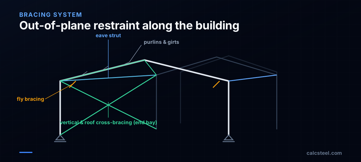
- Rafter stability near the knee: The bottom flange near the eave is in compression under gravity loads. Fly bracing from purlins to the bottom flange is required at intervals not exceeding L_p for the section.
Out-of-plane stability
- Column bracing: Girts (horizontal wall members) brace the outer flange. The inner flange needs fly bracing or a full column strut at the eave.
- Rafter bracing: Purlins brace the top flange. Bottom flange bracing is needed in negative moment regions (near eave and under wind uplift).
- Eave strut: A longitudinal member at the eave connecting all frames, providing out-of-plane stability to the knee connection.
- Vertical bracing: Diagonal bracing in the end bays and at intervals along the building length transfers longitudinal wind loads to the foundations.
Bracing layout
A complete bracing system includes:
- Eave struts along both sides
- Vertical cross-bracing in end bays (at least)
- Roof cross-bracing in end bays
- Fly bracing at critical rafter locations
- Girts on all walls as column restraint
How do you check portal frame deflection and sway?
Strength is not the only limit. A portal frame that is strong enough can still be unserviceable if it sways or sags too much under everyday, unfactored loads, cracking the cladding, jamming roller doors, or unsettling the occupants. Serviceability checks use nominal (unfactored) load combinations and compare the elastic deflections against limits set by the cladding and the project specification.
The two deflections that govern
- Eave sway (δ): horizontal movement of the column head under wind or crane surge.
- Rafter deflection (Δ): vertical sag at midspan under imposed or snow load.
Typical serviceability limits
These vary between AISC Design Guide 3 / MBMA practice and SCI / Eurocode practice, so always confirm the governing code and the project spec. Representative values, applied to the 24 m span / 6 m eave example:
| Deflection | Typical limit | 24 m / 6 m example |
|---|---|---|
| Eave sway, flexible metal cladding | h/150 | 6000/150 = 40 mm |
| Eave sway, masonry or brittle cladding | h/300 | 6000/300 = 20 mm |
| Rafter, imposed / snow | span/200 | 24000/200 = 120 mm |
| Rafter, brittle finishes below | span/360 | 24000/360 = 67 mm |
What to do if a limit governs
Portal frames are flexible in sway because the base is usually pinned. If the sway limit governs, and it often does before strength, the options are, in rough order of cost:
- Deepen the columns (the cheapest stiffness).
- Enlarge the haunch to stiffen the knee.
- Fix the column bases, which roughly halves the sway at the cost of a moment-resisting foundation.
Two cases tighten the limits sharply: where a crane runs on the frame, gantry alignment can demand h/500 to h/1000 (AISC Design Guide 7); and for multi-span frames the differential spread between eaves matters as much as the absolute sway.
Second-order note: the sway you check at serviceability is the amplified (P-Δ) value, not the first-order one. For a flexible portal the amplifier can add 10–30%, so the same second-order analysis used for strength gives the serviceability deflections directly.
How does CalcSteel design portal frames?
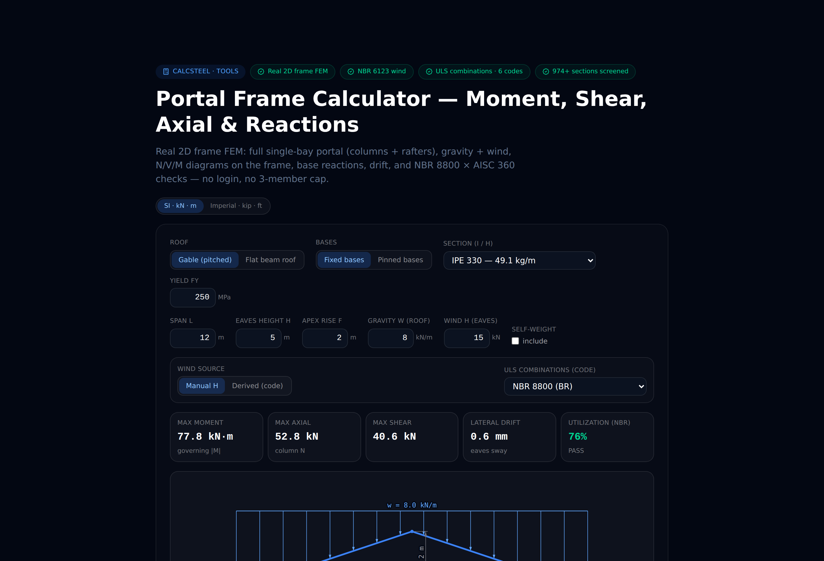
You can try the free portal frame calculator — no signup — right in your browser. CalcSteel provides an end-to-end workflow for portal frame design:
Frame generation
Input span, eave height, pitch, and frame spacing. The software generates the geometry, including optional haunches with parametric depth and length. Multiple bays and lean-to extensions are supported.
Automatic loading
Wind loads are generated from the building envelope using ASCE 7, Eurocode 1, or NBR 6123. Dead, live, snow, and crane loads are applied through the purlin and girt system.
Analysis
A second-order elastic analysis (P-Δ) runs for all load combinations. The Direct Analysis Method is used by default (K = 1.0, reduced stiffness, notional loads).
Member design
Rafter and columns are checked per AISC 360 Chapter H (interaction) with automatic detection of unbraced lengths from the purlin and girt spacing. LTB capacity accounts for the moment gradient (C_b factor).
Connection design
The knee (haunch-to-column) and ridge connections are designed automatically:
- End plate thickness and bolt layout
- Column stiffener requirements
- Weld sizes for the haunch
- Base plate and anchor bolt design
Output
The design report includes the BMD and SFD for every load combination, member utilization ratios, connection details, and a bill of materials with steel weight per square meter of floor area.
Sources
- 1.AISC 360-22, Specification for Structural Steel Buildings
- 2.AISC Design Guide 7: Industrial Buildings — Roofs to Anchor Rods
- 3.ABNT NBR 8800:2008 — Projeto de estruturas de aço
- 4.AISC Design Guide 3: Serviceability Design Considerations for Steel Buildings
- 5.The Steel Construction Institute — Portal frames (steelconstruction.info)
Try CalcSteel for free
Model, analyze and design steel structures in your browser. No install, no signup.
Open the 3D editor