Euler Buckling: Formula, K Factor & AISC Design

Understand Euler's buckling formula, effective length factors (K), slenderness ratio, and how AISC 360-22 Chapter E handles elastic and inelastic column buckling.
A university student? With an academic email (.edu, .ac.uk…) CalcSteel is free for you.What is Euler buckling and why does it matter for steel columns?
Euler buckling is the sudden lateral deflection of a slender column under axial compression. When the compressive load reaches a critical value P_cr, the column snaps sideways — not because the material failed, but because the straight configuration became unstable.
Leonhard Euler derived the critical load in 1744:
P_cr = π²EI / L²
Where E is the modulus of elasticity, I is the moment of inertia about the buckling axis, and L is the column length. This formula shows that buckling capacity depends on stiffness (EI), not strength (F_y). A stronger steel does not help a slender column — only a stiffer or shorter one does.
Buckling matters because it can cause sudden, catastrophic failure without warning. A column designed only for material strength (P = F_y × A) might buckle at a fraction of that load if it is slender. Every steel column design must check buckling per AISC 360-22 Chapter E.

What is the effective length factor K for column buckling?
The effective length factor K accounts for end conditions. A column with fixed ends buckles at a higher load than one with pinned ends because the inflection points (where the curvature reverses) change the effective length.
The general Euler formula becomes:
P_cr = π²EI / (KL)²
Where KL is the effective length — the length of an equivalent pinned-pinned column with the same buckling load.
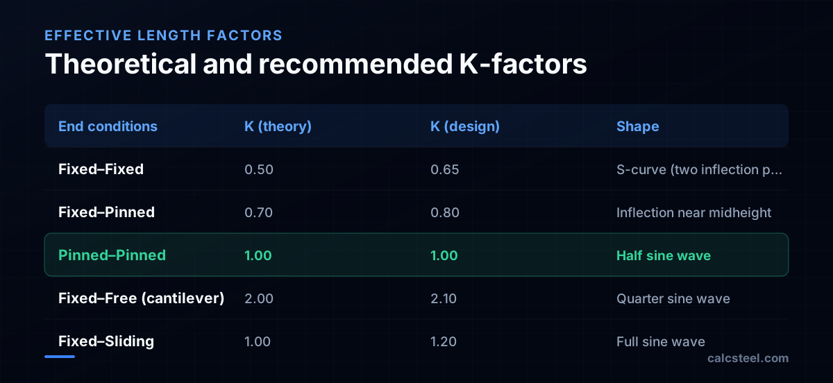
Theoretical vs design K-factors
Theoretical values assume perfect fixity, which never exists in practice. AISC recommends higher design values:
| End conditions | K (theory) | K (design) |
|---|---|---|
| Fixed–Fixed | 0.50 | 0.65 |
| Fixed–Pinned | 0.70 | 0.80 |
| Pinned–Pinned | 1.00 | 1.00 |
| Fixed–Free (cantilever) | 2.00 | 2.10 |
For frames, K depends on whether the frame is braced (no sway) or unbraced (sway permitted):
- Braced frame: K ≤ 1.0 (alignment chart for G_A, G_B)
- Unbraced frame: K ≥ 1.0, often 1.5–2.5
The Direct Analysis Method (DAM) avoids K-factor determination entirely by using K = 1.0 with reduced stiffness and notional loads. This is why DAM is the preferred method in modern practice.
How do you calculate the slenderness ratio of a steel column?
The slenderness ratio is the single most important number in column design:
λ = KL / r
Where r is the radius of gyration (r = √(I/A)). The slenderness ratio must be checked about both axes, and the larger value governs.
Example — W250×73 column, 6 m height, pinned both ends
W250×73 properties: r_x = 110 mm, r_y = 64.5 mm
- KL/r_x = 1.0 × 6000 / 110 = 54.5
- KL/r_y = 1.0 × 6000 / 64.5 = 93.0 ← governs
The column will buckle about the weak axis (y-axis) because the slenderness ratio is higher. This is almost always the case for W-shapes because r_y < r_x.
Slenderness limits
AISC recommends KL/r ≤ 200 for compression members. Above this, the column capacity is so low that it is impractical. For tension members, KL/r ≤ 300 is recommended (not a strength limit, but prevents excessive vibration and sag).
How to reduce slenderness
- Add intermediate bracing — Reduces the effective length. A brace at midheight halves KL.
- Use a section with larger r_y — HSS (square tubes) have equal r in both directions. Wide-flange shapes with wider flanges have better r_y.
- Orient the section correctly — Place the strong axis facing the direction of greatest unbraced length.
- Reduce column height — Add floor framing or mezzanines to break the column into shorter segments.

How does AISC 360 calculate column buckling strength?
AISC 360-22 Chapter E divides the buckling curve into two regimes based on the slenderness ratio:
Inelastic buckling (KL/r ≤ 4.71√(E/F_y))
For A992 steel (F_y = 345 MPa): limit = 4.71√(200000/345) = 113.4
F_cr = 0.658^(F_y/F_e) × F_y
Where F_e = π²E/(KL/r)² is the Euler stress.
This curve accounts for residual stresses and initial imperfections. The column partially yields before buckling, so the capacity is between the squash load (F_y × A) and the Euler load.
Elastic buckling (KL/r > 4.71√(E/F_y))
F_cr = 0.877 × F_e = 0.877 × π²E/(KL/r)²
The 0.877 factor accounts for initial imperfections. The capacity follows the Euler curve but reduced by 12.3%.
Design strength
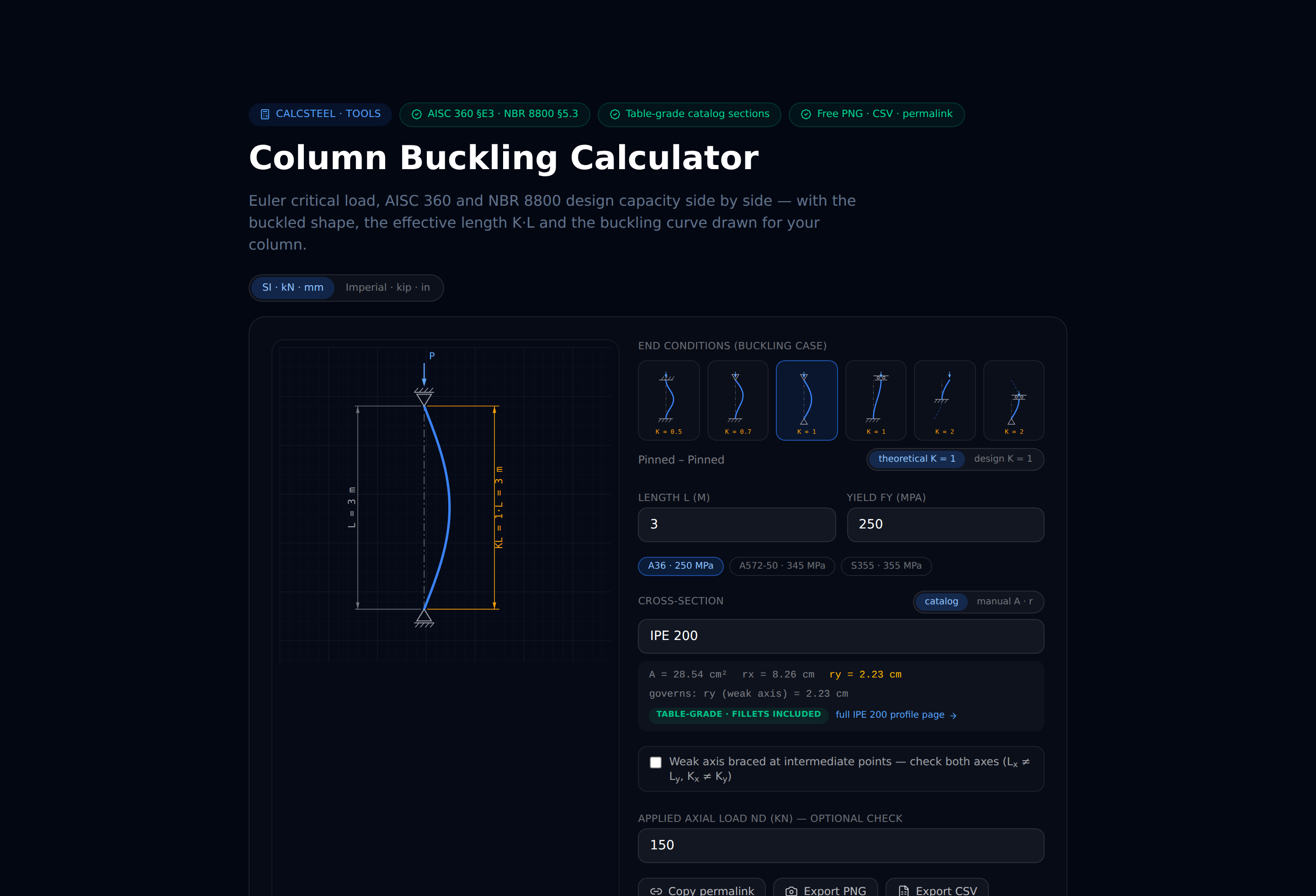
φP_n = φ × F_cr × A_g (φ = 0.90 for LRFD). You can run this entire Chapter E check — K, slenderness and φP_n — in seconds with our free column buckling calculator (no sign-up).
Example — W250×73, KL/r = 93
F_e = π²(200000)/(93)² = 228.1 MPa
Since 93 < 113.4 → inelastic: F_cr = 0.658^(345/228.1) × 345 = 0.658^(1.512) × 345 = 0.538 × 345 = 185.6 MPa
φP_n = 0.90 × 185.6 × 9290 × 10⁻³ = 1551 kN
Compare with the squash load: φP_y = 0.90 × 345 × 9290 × 10⁻³ = 2884 kN. Buckling reduces the capacity to 54% of the squash load.
What is the difference between elastic and inelastic buckling?
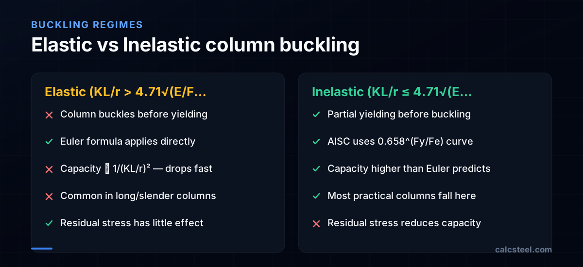
The distinction is critical for understanding why the Euler formula alone is not enough:
Elastic buckling
- The entire cross-section remains elastic when buckling occurs
- Only happens for very slender columns (KL/r > ~113 for A992)
- The Euler formula predicts the capacity reasonably well
- Common in long bracing members, antenna masts, and temporary structures
Inelastic buckling
- Parts of the cross-section have already yielded when buckling initiates
- The effective stiffness is reduced below EI because yielded zones have zero tangent modulus
- Most practical building columns fall in this range
- Residual stresses from the rolling process cause early yielding at flange tips, reducing the effective moment of inertia
Residual stresses
Hot-rolled W-shapes have residual stresses of approximately 70–100 MPa (compressive at flange tips, tensile at the web center). These stresses cause the flanges to yield prematurely under compression, reducing the effective EI before the full cross-section stress reaches F_y.
The AISC column curve (0.658^(Fy/Fe) × Fy) empirically captures this effect. It was calibrated against hundreds of column tests and gives reliable predictions for standard W-shapes.
Transition slenderness
The boundary between inelastic and elastic buckling is at KL/r = 4.71√(E/F_y). For common steel grades:
- A36 (F_y = 250 MPa): KL/r = 133
- A992 (F_y = 345 MPa): KL/r = 113
- A913 Gr 65 (F_y = 450 MPa): KL/r = 99
What are flexural-torsional and torsional buckling modes?
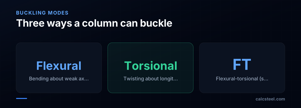
Standard Euler buckling (flexural buckling) is not the only mode. Depending on the cross-section shape, two additional modes can govern (beams face an analogous limit state, lateral-torsional buckling):
Torsional buckling
The column twists about its longitudinal axis without lateral translation. This occurs in doubly symmetric shapes with low torsional stiffness (cruciform sections, built-up columns with thin elements). For standard W-shapes, torsional buckling rarely governs because the warping stiffness is sufficient.
Flexural-torsional buckling
The column simultaneously bends and twists. This is the critical mode for singly symmetric shapes (channels, structural tees, single angles) and unsymmetric shapes. The buckling load is lower than either the flexural or torsional mode alone.
AISC E4 provides the equations:
For doubly symmetric: check flexural buckling about each axis and torsional buckling — the lowest governs.
For singly symmetric (e.g., WT): F_e = [(F_ey + F_ez) / 2H] × [1 − √(1 − 4F_ey × F_ez × H / (F_ey + F_ez)²)]
Where H = 1 − (x₀² + y₀²)/r̄₀² accounts for the distance between the shear center and centroid.
Practical implications
- W-shapes: Almost always governed by flexural buckling about the weak axis
- Single angles: Must check flexural-torsional buckling per AISC E5
- WT sections: Flexural-torsional about the axis of symmetry often governs
- HSS: Flexural buckling only (doubly symmetric, high torsional stiffness)
How do laced and battened built-up columns change the buckling check?
Sometimes a single rolled shape cannot give a column enough radius of gyration on its weak axis. The classic fix is a built-up column: two channels, or two angles, set apart and tied together with diagonal lacing bars or with batten plates, so the pair acts as one member with a healthy r about both axes. Spacing the components apart buys stiffness cheaply, and it lets you balance the two buckling axes instead of paying for a heavy solid section.
A built-up column is not quite as strong as a solid section with the same moment of inertia, and AISC 360-22 Section E6 explains why. The two axes behave very differently:
- The material axis, the one whose plane cuts through both components, sees the pair act as a single solid piece. Nothing needs to change here.
- The free axis, the open axis perpendicular to the plane of the connectors, is the problem. As the column bows about this axis, one component is driven into more compression than the other, and that difference has to pass between them as longitudinal shear, carried by the lacing or the battens. The connectors are not perfectly rigid, so the components slip a little, and the built-up member ends up more slender than its gross moment of inertia suggests.
AISC folds the connector slip into a modified slenderness ratio that applies only to the free axis:
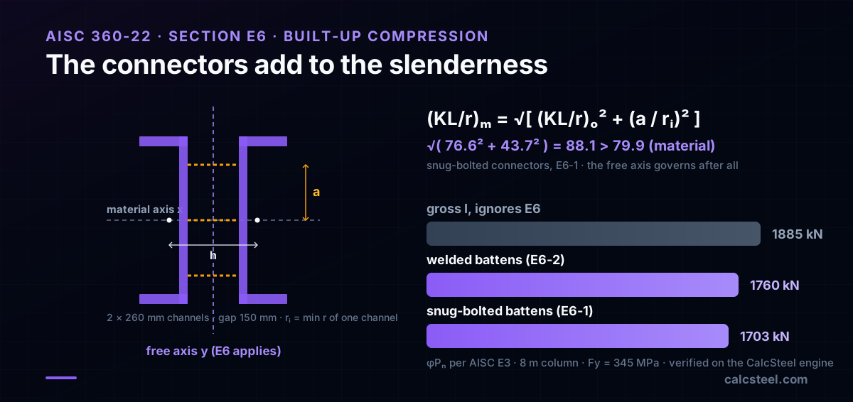
Snug-tight bolted connectors (E6-1): (KL/r)_m = √[ (KL/r)_o² + (a/r_i)² ]
Welded or pretensioned bolted connectors (E6-2): (KL/r)_m = √[ (KL/r)_o² + 0.82 · α²/(1+α²) · (a/r_ib)² ], with α = h/(2 r_ib)
Here (KL/r)_o is the slenderness of the built-up member acting as a unit about the free axis, a is the spacing between connectors along the length, r_i is the minimum radius of gyration of a single component, r_ib is the component radius of gyration about its own centroidal axis parallel to the buckling axis, and h is the distance between the component centroids. Welded and pretensioned connectors are stiffer, so they add less to the slenderness than snug-tight bolts do.
Two limits keep the modification honest (E6.2). The connectors must be close enough that a/r_i stays at or below three quarters of the governing built-up slenderness, and no single component may be more slender between connectors than the whole member. Space the battens too far apart and one channel buckles on its own, long before the built-up curve predicts.
Worked example: a battened two-channel column, step by step
Take two 260 mm hot-rolled channels (web 260, flange 90, web thickness 10, flange thickness 14 mm), set web to web with a 150 mm gap and tied with bolted batten plates. The column is 8.0 m long, pinned at both ends (K = 1.0), with F_y = 345 MPa. CalcSteel's section engine gives each channel A = 4840 mm², r_x = 100.2 mm and r_y = 27.5 mm, with the centroid 25.8 mm from the back of the web.
Composite section
With the two centroids 201.7 mm apart, the parallel-axis theorem gives A = 9680 mm², r_x = 100.2 mm about the material axis and r_y = 104.5 mm about the free axis. The gap was chosen so the two axes are almost balanced, which is the whole point of building the column up.
- Material axis: KL/r_x = 8000 / 100.2 = 79.9
- Free axis, acting as a unit: (KL/r)_o = 8000 / 104.5 = 76.6
Read naively, the material axis looks like it governs, and the check would report φP_n = 1885 kN.
The connectors change the answer
The batten plates are bolted snug-tight and spaced a = 1200 mm apart. The minimum radius of gyration of one channel is r_i = 27.5 mm, so a/r_i = 43.7. Equation E6-1 gives:
(KL/r)_m = √(76.6² + 43.7²) = 88.1
The modified free-axis slenderness (88.1) now exceeds the material-axis value (79.9), so the free axis governs after all. Running the AISC Chapter E curve at KL/r = 88.1: F_e = 254.1 MPa, and because 88.1 is below the transition limit of 113.4, F_cr = 0.658^(345/254.1) × 345 = 195.4 MPa. The design strength falls to φP_n = 0.90 × 195.4 × 9680 × 10⁻³ = 1703 kN, a 9.7% loss that the gross moment of inertia never hinted at.
Welded connectors bite less
Weld the battens instead of bolting them snug and equation E6-2 applies. With α = h/(2 r_ib) = 201.7 / (2 × 27.5) = 3.67, the slenderness rises only to (KL/r)_m = √(76.6² + 0.82 × 3.67²/(1+3.67²) × 43.7²) = 85.5, giving F_cr = 202.0 MPa and φP_n = 1760 kN. Stiffer connectors, smaller penalty: the connection detail is a design variable, not an afterthought.
Every number here was computed by CalcSteel's shipping section and Chapter E engine and matches the hand calculation to three decimals. You can reproduce the base curve in the free column buckling calculator by entering the modified effective length KL = (KL/r)_m × r.
How do you prevent column buckling in practice?
Preventing buckling is about controlling the slenderness ratio KL/r. The most effective strategies are:
1. Reduce the effective length (KL)
- Add bracing: Intermediate lateral bracing at the weak axis reduces KL/r_y. Even one brace at midheight doubles the capacity in the inelastic range.
- Fix end conditions: Moment connections at beam-column joints reduce K below 1.0 in braced frames.
- Use the Direct Analysis Method: K = 1.0 always, which often gives a less conservative effective length than the alignment chart for braced frames.
2. Increase the radius of gyration (r)
- Select wider sections: W360 shapes have larger r_y than W610 shapes at similar weights. The column tables in the AISC Manual are sorted by φP_n to make this comparison easy.
- Use HSS or pipe: Square HSS and round pipe have equal r about both axes, eliminating the weak-axis penalty.
- Use built-up sections: For heavy columns, two channels laced together or a W-shape with cover plates can achieve very high r values.
3. Design the frame for braced behavior
- Use diagonal bracing, shear walls, or a rigid core to prevent sway. Braced frames have K ≤ 1.0 for all columns, which dramatically increases column capacity.
- Even a few braced bays can stabilize an entire building floor.
Column splices
At column splices (typically every 2–3 stories), ensure the splice can transfer the full buckling load. A splice that fails under buckling load nullifies the bracing above it.
How does CalcSteel check column buckling automatically?
CalcSteel's structural engine performs comprehensive column buckling checks for every compression member:
What is checked
- Flexural buckling about both axes (AISC E3) — using the actual effective lengths from the analysis model
- Torsional and flexural-torsional buckling (AISC E4) — automatically activated for channels, tees, angles, and built-up sections
- Local buckling — flange and web slenderness checks per Table B4.1a. Non-compact or slender elements reduce the critical stress.
- Built-up member provisions (AISC E6) — modified slenderness for laced and battened columns
Direct Analysis Method
The engine applies DAM by default:
- K = 1.0 for all members
- Notional loads at 0.2% of gravity per level
- Reduced stiffness: 0.8τ_b × EI and 0.8EA
This means the buckling check uses the rigorous second-order forces with K = 1.0, giving the most reliable results.
Results visualization
Column utilization ratios are displayed in the 3D view with color coding. You can click any column to see:
- The governing slenderness ratio and axis
- F_cr and φP_n values
- The buckling mode (flexural, torsional, or flexural-torsional)
- The demand-to-capacity ratio for each load combination
If a column fails, the section optimizer suggests the lightest replacement that passes all checks.

Sources
Try CalcSteel for free
Model, analyze and design steel structures in your browser. No install, no signup.
Open the 3D editor