Diagonal Steel Bracing: the Full-Length Slenderness Criterion Behind the Code
Diagonal steel bracing is the plainest lateral system there is: one diagonal carrying the story shear straight to the foundation. The whole design turns on the fact that under load reversal that diagonal has to work in compression, unbraced over its full length. Here is the criterion behind the code, with a worked check on a real SHS 150 x 150 x 6 diagonal.
Key takeaways
- A single diagonal is statically determinate for lateral load: it takes the whole story shear, so the axial demand is exact statics, Pu = Vu / cos a = 300 / 0.864 = 347 kN, in tension one way and compression the other.
- The criterion behind the code is the compression check, because buckling makes the compression capacity far smaller than the tension capacity: our tube keeps only 36 % of its squash load once you account for buckling.
- The single diagonal has no crossing point to brace it, so it buckles over its FULL work-point length with K = 1.0. That is the whole difference from an X-brace, where the tension diagonal braces the crossing and K drops to about 0.5.
- Worked SHS 150 x 150 x 6, Fy = 345 MPa: KL/r = 118 (Euler range), phiPn = 386 kN against Pu = 347 kN, a 90 % check. The same tube as an X-brace would carry 832 kN, 2.15 times more, purely because it is braced at midlength.
- Two gates bracket the member: the code slenderness cap KL/r <= 200 (ours 118, fine) and, for seismic braced frames, tighter width-thickness and slenderness rules that this section meets for compression but not for a highly ductile SCBF.
What diagonal steel bracing really is
Diagonal steel bracing is the workhorse of lateral stability: a single diagonal member set into a rectangular bay, turning a hinge-prone rectangle into a stiff triangle. Push the top of the bay sideways and the diagonal picks up the load as pure axial force, then hands it down to the foundation. No bending, no frame action, just a strut and a tie doing the simplest job in structural steel.
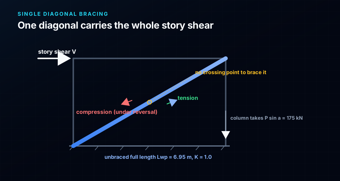
The catch is hidden in the word reversal. Wind and earthquake push both ways, so the same diagonal is a tie in one direction and a strut in the other. As a tie it is almost unkillable; steel is superb in tension. As a strut it can buckle, and a single diagonal has nothing bracing its midpoint, so it buckles over its full length. That is the number the whole design turns on.
This article derives that criterion from first principles, then runs a full worked check on a real SHS 150 x 150 x 6 diagonal. It is the single-diagonal companion to our steel cross bracing article: there, two diagonals share the bay and the tension one braces the crossing point, so the compression diagonal only buckles over half its length. Here there is no crossing point, and paying for the full length is the entire story.
Single diagonal vs X, chevron and K: the configurations
Here is a 40-word definition you can quote: diagonal steel bracing is a concentrically braced system in which one or more diagonal members carry lateral load as axial force to the foundation; the single diagonal is the base case, where one member alone resists the story shear in both tension and compression.
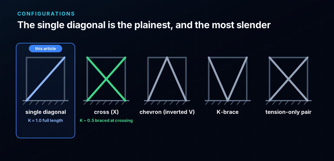
There are five common ways to brace a bay, and they differ mostly in what happens to the compression diagonal:
- Single diagonal: one member, unbraced over its full length, K = 1.0. The simplest and the most slender. This article.
- Cross (X): two diagonals; the tension one braces the crossing point, so the compression diagonal uses roughly half its length, K ~ 0.5. The effective-length criterion is its whole story.
- Chevron (inverted V): two diagonals meeting the beam at midspan; the beam must carry the unbalanced vertical force when the compression brace buckles and sheds load.
- K-brace: diagonals meeting a column at midheight; discouraged in seismic design because a buckling brace pushes laterally on the column.
- Tension-only pair: two slender diagonals, each designed to work only in tension while the other goes slack. Cheap, but no compression path, so it is barred from ductile seismic systems.
The single diagonal is the reference against which the others are shortcuts. The buckling it suffers over the full length is exactly the Euler buckling of a slender strut, scaled by the effective-length K factor. Get those two and the criterion follows.
Why the compression brace governs, not the tension one
Beginners size a brace for the tension force and move on. That is backwards. Under reversal the diagonal sees the same axial magnitude in tension and in compression, but the two capacities are wildly different, and the smaller one wins.
In tension, the member yields across its gross area: Pn = Fy Ag, with almost nothing lost. For our tube that is 1192 kN of squash load, and the design tension strength is 1073 kN.
In compression, the member does not reach yield; it buckles first, at the critical stress Fcr, which drops down the Euler curve as slenderness grows. For the same tube at K = 1.0 the compression capacity collapses to Pn = 429 kN, only 36 % of the squash load. Buckling throws away nearly two thirds of the steel's strength.
So the design is a compression problem wearing a tension member's clothes. Size the diagonal so it survives buckling and the tension check passes automatically with enormous margin. That is why every line below is about Fcr, KL/r and the column curve, and why the tension check is a one-line afterthought at the end. It is the mirror image of a buckling restrained brace, which spends real money to delete exactly this penalty.
The criterion behind the code, from first principles
Start with the compression member. Its usable strength is the critical stress times the area, and the critical stress comes from the column curve. Below the elastic transition the failure is inelastic (the section partly yields as it buckles); above it the failure is elastic Euler buckling. In AISC 360 form:
Fe = π2E / (KL/r)2, the elastic (Euler) buckling stress
Fcr = 0.658(Fy/Fe) Fy if KL/r ≤ 4.71√(E/Fy), else Fcr = 0.877 Fe
The design compression strength is φcPn = φcFcrAg with φc = 0.90. Everything hinges on the slenderness KL/r, and the effective length KL is where the single diagonal differs from every other configuration.
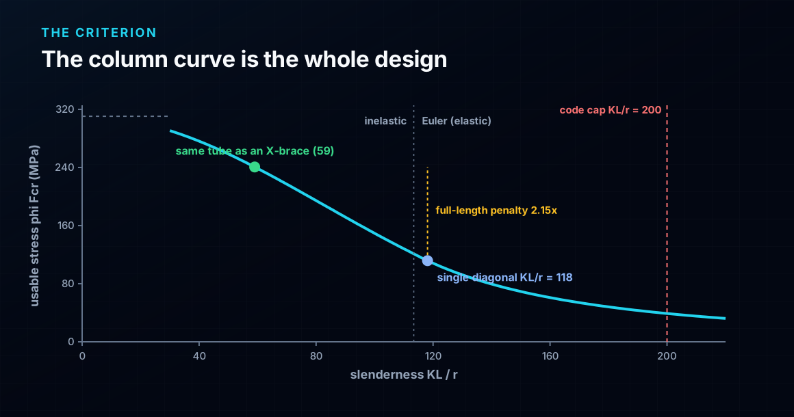
For a single diagonal pinned at both ends there is no intermediate brace point, so the effective length is the full work-point length: K = 1.0, KL = Lwp. For the same physical tube used as an X-brace, the tension diagonal holds the crossing point still, halving the buckling length to roughly K = 0.5. On the column curve that halving is enormous, because Fe scales with 1/(KL/r)2. The figure shows the two points on the same tube: the single diagonal sits low on the Euler branch, the X-brace sits high on the inelastic branch, a 2.15x difference in usable stress from the effective length alone.
That is the criterion behind the code for a single diagonal: φcFcrAg ≥ Pu, evaluated at the full length K = 1.0, backed by a hard cap on how slender the member is allowed to be, KL/r ≤ 200. Where an X-brace lets you cheat the length, the single diagonal makes you pay it in full.
The capacities you need, and which one governs
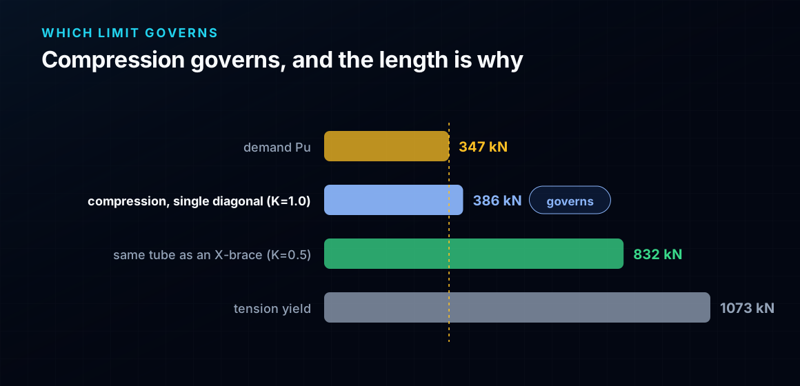
Four axial numbers decide a single diagonal, and they line up in a way worth seeing before the arithmetic. From smallest capacity margin to largest:
- The demand, Pu = 347 kN, the same in tension and compression under reversal.
- Compression, single diagonal (K = 1.0): φPn = 386 kN. This is the binding capacity, only just above the demand. It is the whole design.
- Compression, same tube as an X-brace (K = 0.5): φPn = 832 kN. The identical section, braced at midlength, has more than double the capacity. This bar is why people reach for an X.
- Tension yield: φPn = 1073 kN. Miles above the demand. Tension never comes close to governing a slender diagonal.
Put those four on one axis and the message is immediate: the compression bar for the single diagonal is the short one, sitting right on top of the demand line, while tension towers over everything. The design lives and dies on that one short bar, and the short bar is short because of the length. This is also what separates member design from stability bracing: a diagonal here is a load path sized by its own buckling, not a small nodal brace sized by the 2 % rule in bracing stiffness and strength.
Worked check, part 1: the demand and the section
The bay and the demand
Take a single-diagonal bay L = 6.0 m wide and h = 3.5 m tall, so the diagonal runs at α = 30.3° over a work-point length Lwp = 6.95 m (cos α = 0.864). A single diagonal in a pinned bay is statically determinate for lateral load, so it takes the whole story shear. For a design story shear Vu = 300 kN:
Pu = Vu / cos α = 300 / 0.864 = 347 kN (tension one way, compression the other)
Pick a trial section
Try a square hollow section, SHS 150 x 150 x 6, in ASTM A500 Gr. C, Fy = 345 MPa (the 50 ksi of the AISC tables). Its properties: gross area Ag = 3456 mm², second moment I = 1196 cm&sup4;, radius of gyration r = 58.8 mm. A closed tube is the natural choice for a brace: the same r about both axes, high torsional stiffness, and clean connections.
Check the wall first. The flat width-to-thickness is b/t = (150 - 3·6)/6 = 22.0, below the nonslender limit 1.40√(E/Fy) = 33.7, so the wall is fully effective and no local-buckling reduction applies. Now the member.
Worked check, part 2: the full-length buckling check
This is the criterion in numbers. The single diagonal is pinned at both ends with no intermediate brace, so K = 1.0 and the effective length is the full work-point length, KL = 6.95 m. The slenderness is:
KL/r = 1.0 · 6950 / 58.8 = 118
Compare it with the transition 4.71√(E/Fy) = 113. Since 118 > 113, the diagonal is in the elastic (Euler) range: it buckles before it yields. The elastic buckling stress and the critical stress are:
Fe = π2E / (KL/r)2 = π2·200000 / 1182 = 141.6 MPa
Fcr = 0.877 Fe = 124.2 MPa
So the compression capacity is Pn = FcrAg = 124.2 · 3456 = 429 kN, and the design strength is
φcPn = 0.90 · 429 = 386 kN ≥ 347 kN (utilisation 90 %)
The tube passes, at 90 %. Notice how little of the steel you got to use: the squash load FyAg is 1192 kN, and buckling over the full length leaves only 429 kN, about 36 %. Now the payoff of the comparison: the identical tube used as an X-brace diagonal, braced at its crossing so KL = 3.47 m and KL/r = 59, sits on the inelastic branch with Fcr = 267 MPa and φcPn = 832 kN, a utilisation of just 42 %. Same steel, same weight, 2.15 times the capacity, purely because something braced its midpoint.
See it yourself: the live buckling calculator
The whole single-diagonal design is the collapse of φcFcr with slenderness, and you can watch it happen. In the calculator below, take a compression member and push its length up: the critical load falls down the Euler curve, exactly the fall that turns 832 kN into 386 kN when a brace point disappears and K goes from 0.5 to 1.0.
Try our numbers first, r = 58.8 mm and KL = 6.95 m, and watch the capacity land near 429 kN. Then halve the length and watch it more than double. That single slider is the difference between a single diagonal and an X-brace. Read the theory in Euler buckling explained, then come back and size your own diagonal.
End conditions (buckling case)
Pinned – Pinned
Cross-section
Slenderness KL/r
134.7
limit 200 · OK
Euler Pcr (elastic)
310.7 kN
Fe = 108.9 MPa
AISC 360 φcPn
245.2 kN
Fcr = 95.5 MPa · elastic
NBR 8800 Nc,Rd
247.7 kN
χ = 0.382 · λ₀ = 1.52
Code vs code — same column
Nc,Rd / φcPn = 1.010
Both codes share the 0.658 / 0.877 buckling curve — the ~1% gap is purely φc = 0.90 (AISC) vs 1/γa1 = 0.909 (NBR).
Demand check — Nd = 150 kN
Step-by-step derivation — live for YOUR column
IPE 200 · L = 3 m · K = 1 · fy = 250 MPa
- 1
Slenderness ratio
λ = K·L/r = 1 × 3000 / 22.28 mm
λ = 134.7 (≤ 200 ✓)
- 2
Euler elastic buckling stress and load
Fe = π²E/λ² = π² × 200,000 / 134.7² · Pcr = Fe·A = Fe × 2854 mm²
Fe = 108.9 MPa · Pcr = 310.7 kN
- 3
Buckling regime (AISC E3)
4.71·√(E/fy) = 4.71·√(200,000/250) = 133.2 < λ = 134.7
elastic buckling → use E3-3 (0.877·Fe)
Elastic range: capacity no longer depends on fy — only geometry (r, K, L) helps.
- 4
AISC 360 critical stress and design capacity
Fcr = 0.877 · Fe = 0.877 × 108.9 = 95.5 MPa · φcPn = 0.9 × Fcr × A
Pn = 272.5 kN · φcPn = 245.2 kN
- 5
NBR 8800 reduction factor and design capacity
λ₀ = √(fy/Fe) = 1.515 > 1.5 → χ = 0.877/λ₀² = 0.382 · Nc,Rd = χ·A·fy/1.1
Nc,Rk = 272.5 kN · Nc,Rd = 247.7 kN
Same 0.658/0.877 curve as AISC — the ~1% difference is φc = 0.90 vs 1/γa1 = 0.909.
Sections that work — 3 lightest of 612 catalog profiles carrying Nd = 150 kN at L = 3 m, K = 1
| Section | kg/m | φcPn (kN) | Nc,Rd (kN) | Util. | |
|---|---|---|---|---|---|
| lightestSHS 80x4 | 9.2 | 164 | 166 | 91% | |
| HSS 76x76x4.8 | 9.9 | 165 | 167 | 91% | |
| CHS 88.9x5 | 10.3 | 172 | 174 | 87% |
Pass criterion: φcPn ≥ Nd (AISC 360 LRFD) AND Nc,Rd ≥ Nd (NBR 8800) AND KL/r ≤ 200, using each section's tabulated-mass area and minimum radius of gyration.
Buckling curve — IPE 200, fy = 250 MPa
Capacity of IPE 200 by unbraced length — K = 1, fy = 250 MPa
| L (m) | KL/r | Pcr Euler (kN) | φcPn AISC (kN) | Nc,Rd NBR (kN) | Regime |
|---|---|---|---|---|---|
| 1 | 45 | 2,796 | 577 | 583 | inelastic |
| 2 | 90 | 699 | 419 | 423 | inelastic |
| 3◀ yours | 135 | 311 | 245 | 248 | elastic |
| 4 | 180 | 175 | 138 | 139 | elastic |
| 5 | 224 ⚠ | 112 | 88 | 89 | elastic |
| 6 | 269 ⚠ | 78 | 61 | 62 | elastic |
| 7 | 314 ⚠ | 57 | 45 | 45 | elastic |
| 8 | 359 ⚠ | 44 | 34 | 35 | elastic |
| 9 | 404 ⚠ | 35 | 27 | 28 | elastic |
| 10 | 449 ⚠ | 28 | 22 | 22 | elastic |
Worked check, part 3: where the demand comes from
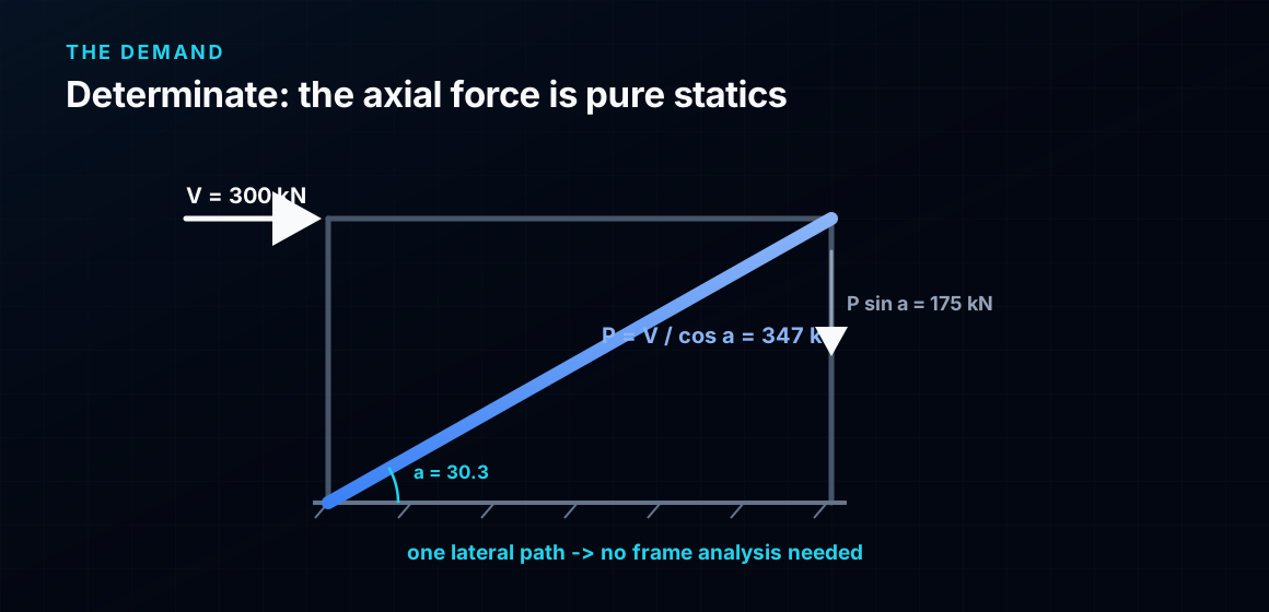
Strength checks out, but where does the demand Pu come from? Here the single diagonal is as easy as it gets. A single-diagonal bay with pinned ends is statically determinate for lateral load: the diagonal is the only lateral path, so it carries the entire story shear and the axial force follows from equilibrium alone, no frame analysis needed.
- Brace axial: Pu = Vu / cos α = 300 / 0.864 = 347 kN.
- Column axial from the brace: the vertical component Pu · sin α = 347 · 0.504 = 175 kN is delivered into the column, part of the overturning couple.
- Global equilibrium: the base reactions balance the applied shear (ΣFx = 300 kN) and the overturning moment Vu·h = 1050 kN·m, a quick sanity check.
That determinacy is a genuine advantage of the single diagonal. An eccentrically braced frame is indeterminate and needs an analysis to find its link force; a single diagonal you can check on the back of a drawing. The trade is that a lone diagonal is one-sided: it is stiffer in the direction that puts it in tension. Real buildings pair diagonals in opposite bays, or use an X, so both directions get a compression-capable brace.
The slenderness cap and the tension-only trap
Two limits sit on top of the strength check, and both catch real designs.
The slenderness cap. AISC 360 recommends KL/r ≤ 200 for compression members, and it is effectively mandatory for a brace: past it the member is so limp it buckles under its own handling and the compression capacity is negligible. Our diagonal is at 118, comfortably inside. If it had come out at, say, 240, no amount of stress check would save it; you would shorten the brace, add an intermediate brace point, or go to a stockier section. This cap is why very long single diagonals quietly become X-braces or get a midpoint strut.
The tension-only trap. It is tempting to argue that the diagonal only needs to work in tension, let it buckle harmlessly in compression, and size it as a slender rod. That is legal for wind in ordinary buildings with a pair of diagonals, one for each direction, and it is genuinely cheap. But a lone tension-only diagonal braces the frame in one direction only, and tension-only systems are barred from ductile seismic braced frames precisely because a brace that buckles and never recovers cannot dissipate energy. In seismic design, AISC 341 goes further: a special concentrically braced frame (SCBF) wants a highly ductile section, b/t ≤ 0.55√(E/Fy) = 13.2, which our 22.0 wall does not meet. Our tube is a fine wind or ordinary-frame brace; a highly ductile SCBF would need a thicker wall.
Common mistakes & FAQ
The errors that most often turn a textbook-correct diagonal into a failed check:
- Sizing for tension. The compression capacity is the small one; a slender diagonal designed on its tension force is badly undersized. Always check compression at the full length first.
- Borrowing the X-brace effective length. A single diagonal has no crossing point, so K = 1.0, not 0.5. Using 0.5 out of habit roughly doubles the apparent capacity and the brace can fail at half the load you thought.
- Forgetting the reversal. Wind and seismic act both ways. A diagonal that is only ever a tie in your model is a strut in the real event; design it for both.
- Ignoring the slenderness cap. KL/r must be ≤ 200. It is a separate gate from the stress check and it governs long braces.
- Using the wrong r. For an angle or a tee the governing radius of gyration is the smallest one (often rz for a single angle), not rx. A square tube dodges this because r is equal about both axes.
- Designing the connection for the brace demand. In a seismic braced frame the gusset and welds are sized for the brace's expected strength (RyFyAg in tension, the post-buckling force in compression), not the 347 kN load-case value.
FAQ
Single diagonal or X-brace? An X is more efficient because it halves the compression buckling length and braces both directions at once, but it needs the space for two diagonals and a working crossing detail. A single diagonal is simpler and cheaper per bay, at the cost of a heavier section and one-sided stiffness. Pair single diagonals in opposite bays to get both directions.
Why is K = 1.0 and not 0.5 here? K = 0.5 in an X comes from the tension diagonal holding the crossing point still, which shortens the buckling length of the compression diagonal. A single diagonal has no such point, so it buckles over its whole length and K = 1.0. See the effective-length K factor.
Can I just use a tension-only rod? For wind in an ordinary building, with a pair of rods for the two directions, yes, and it is cheap. For a ductile seismic braced frame, no: the code needs a compression-capable, appropriately ductile brace.
Key takeaways
Diagonal steel bracing is the simplest lateral system, and its design is one honest idea: the diagonal must survive compression, unbraced over its full length.
- The criterion is the full-length compression check, φcFcrAg ≥ Pu at K = 1.0, plus the cap KL/r ≤ 200. Compression governs because buckling leaves only 36 % of the squash load.
- The demand is pure statics: a single diagonal is determinate, Pu = Vu/cos α = 347 kN, in tension one way and compression the other.
- Worked SHS 150 x 150 x 6, Fy = 345: KL/r = 118 (Euler range), φPn = 386 kN vs 347 kN, a 90 % check, all hand-checked and matching AISC Manual Table 4-22.
- The same tube as an X-brace carries 832 kN, 2.15 times more, because the crossing braces its midpoint. That contrast is the reason to know which one you are designing.
Want to try the numbers on your own diagonal? The column buckling calculator and the full CalcSteel editor are free to use, and CalcSteel is free for students. Size the diagonal at its full length, check KL/r against 200, and let the compression bar tell you the section.
Sources
- 1.AISC 360-16, Specification for Structural Steel Buildings (Ch. E compression, Ch. D tension)
- 2.AISC Steel Construction Manual, Table 4-22, Available Critical Stress for Compression Members
- 3.AISC 341-16, Seismic Provisions for Structural Steel Buildings (§F1 OCBF, §F2 SCBF)
- 4.ASCE/SEI 7, Minimum Design Loads and Associated Criteria (seismic R, load combinations)
- 5.ABNT NBR 8800, Projeto de estruturas de aco e de estruturas mistas de aco e concreto
Try CalcSteel for free
Model, analyze and design steel structures in your browser. No install, no signup.
Open the 3D editor