Bracing Stiffness and Strength: What a Brace Must Actually Deliver to Count as a Brace
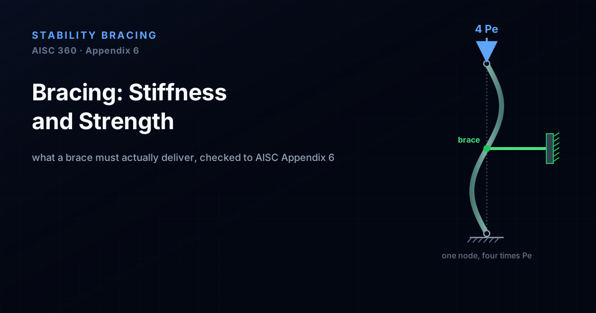
A brace can be present, correctly connected, and still fail to brace. To hold a column or a beam at its buckling point a brace has to deliver two separate things: enough stiffness to change the buckling mode, and enough strength to survive the force that mode change demands. This guide derives both from Winter's model, measures the ideal stiffness on the CalcSteel buckling engine (a midheight brace lifts an IPE 300's critical load from 186 kN to 744 kN, a clean fourfold jump), and shows why AISC 360 Appendix 6 asks for roughly twice the ideal stiffness and about 1% of the column force, with a free live calculator.
Key takeaways
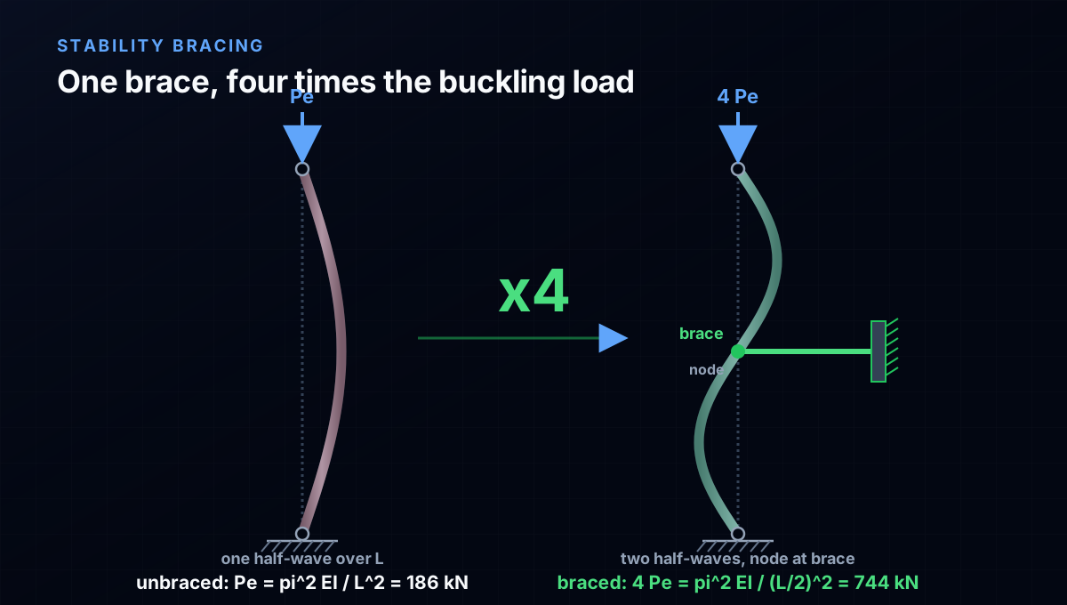
- A brace does its job by shortening the unbraced length. Put a stiff brace at the midheight of a pin-ended column and it buckles between braces instead of over its full length, so the elastic critical load jumps from Pe = pi^2 EI/L^2 to 4 Pe = pi^2 EI/(L/2)^2. The CalcSteel buckling engine confirms it exactly on an 8 m IPE 300: 186 kN to 744 kN.
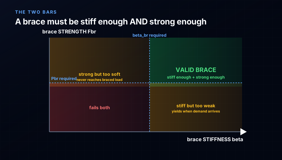
- A brace must deliver stiffness AND strength, and neither alone is enough. Stiffness is what lets the column reach the higher braced load at all; strength is what keeps the brace from yielding once the column's unavoidable crookedness pushes real force into it. A strong but flexible brace never delivers the braced load; a stiff but weak brace tears when the load arrives.
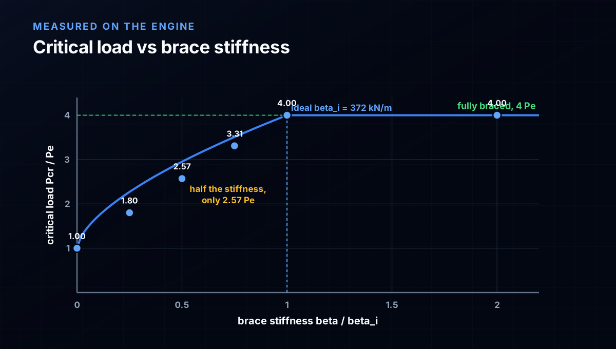
- There is an ideal (minimum) stiffness that just barely forces the braced mode. Winter's rigid-bar model gives beta_i = 2 Pr/Lb for a single midheight brace, and the engine measures the saturation point at exactly 371.9 kN/m against Winter's 371.9 kN/m, agreement to four significant figures. Below beta_i you get only part of the jump: at half the ideal stiffness the load reaches just 2.57 Pe, not 4 Pe.
- Ideal stiffness is never enough on its own, because a real column is not straight. With an initial crookedness of Lb/500, a brace exactly at beta_i would need infinite strength. AISC therefore requires roughly twice the ideal stiffness, which caps the brace force at about 0.8% of the column load; the specification rounds nodal bracing up to 1% (Pbr = 0.01 Pr) and 2 Pr/Lb -> (1/phi)(8 Pr/Lb) for stiffness.
- The brace force is small but the stiffness demand is real. For the worked IPE 300 the required nodal brace force is only 7.4 kN (1% of 744 kN), a force almost any member carries, but the required stiffness of about 1980 kN/m is what a slender brace or a flexible connection actually fails. Stiffness, not strength, is usually the governing half, and connection flexibility counts inside it.
The brace that was there and did not brace
Every stability failure investigation seems to turn up the same photograph: a diagonal, an angle, a rod, bolted neatly into place, doing exactly nothing. The brace was present. It was connected. And the column next to it still buckled as if the brace were not there. The reason is almost never that the brace was too weak. It is that the brace was too soft.
This is the part of stability that surprises people the first time. We are trained to size members for force: find the demand, pick a section, check that its capacity beats the demand. A brace does not work that way. A brace is not primarily a force-carrying member; it is a stiffness device. Its job is to hold a point on a column or a beam still enough that the member is forced to buckle in a shorter, stronger mode. And holding a point still is a question of stiffness first, strength second.
So a brace has to deliver two separate things, and getting one right does not get you the other. It needs enough stiffness to change the buckling mode at all, and enough strength to survive the force that the mode change, plus the column's unavoidable crookedness, pushes back into it. This guide is written for the student meeting AISC Appendix 6 or Salmon and Johnson's chapter 16 for the first time, and for the practising or freelance engineer who wants to see the two requirements derived, measured on a real buckling engine, and turned into the two code checks that actually govern. Every number below is computed: some by hand from Winter's model, some by the CalcSteel finite-element buckling solver, and the two agree.
What a brace actually does: it shortens the unbraced length
Start with the thing a brace buys you. An axially loaded column pinned at both ends buckles at the Euler load, Pe = pi^2 EI / L^2, in a single smooth bow over its full length L. The buckled shape has its largest lateral displacement at midheight. That is precisely where a brace does the most good.
Hold that midheight point against sideways movement and the column can no longer bow in one long half-wave. The lowest shape it has left is an S: two half-waves, one in each half, with a stationary node at the brace. Each half now behaves like a pinned column of length L/2, so the critical load becomes pi^2 EI / (L/2)^2 = 4 Pe. One brace at the right place quadruples the buckling load. The member did not get stronger in any material sense; its unbraced length got shorter, and the buckling load scales with one over that length squared.
Put concrete numbers on it. Take an IPE 300 (area 53.8 cm2, weak-axis Iy = 603 cm4), 8 m long, in A992 steel, loaded so it wants to buckle about its weak axis, the axis a brace usually controls. By hand, Pe = pi^2 (200 GPa)(603 cm4)/(8 m)^2 = 186 kN. Brace the midheight and the theory says 4 Pe = 744 kN. When we hand this exact model to the CalcSteel linear buckling analysis, the unbraced column returns 186.0 kN, matching the Euler value to three decimals, and the second mode of that same column, the S-shape with a node at midheight, sits at 743.9 kN. The brace does not create the braced load out of nothing; it simply makes the column's own second mode the one that governs.
Two requirements, and why one without the other is useless
Now the catch. That 4 Pe assumed a rigid brace: a point held perfectly still. Real braces are springs, not rigid supports. A diagonal has axial flexibility EA/L; its end connection has slip and bolt-hole clearance; the point it braces to may itself move. The real question is not whether a brace exists, but whether it is stiff enough and strong enough, and those are two different tests a brace can pass or fail independently.
Stiffness decides whether the column can reach the braced load at all. Feed a column a brace that is too soft and it does not jump to 4 Pe; it lands somewhere in between, because the brace lets its point drift and the column buckles in a compromise shape longer than L/2. Stiffness is what changes the buckling mode.
Strength decides whether the brace survives once it is doing its job. A column is never perfectly straight. Its small initial crookedness means that under load the braced point genuinely pushes sideways on the brace, and the brace has to push back with a real force without yielding or buckling itself. Strength is what carries that force.
The two failure modes are distinct. A brace that is strong but flexible, a fat bar on a long soft reach, never delivers the braced load: the column buckles early at a load the brace's strength was never asked about. A brace that is stiff but weak, a short stubby element that yields at low force, holds the point right up until the demand arrives, then tears and lets the column go. A real brace has to clear both bars. The rest of this guide is about where those two bars sit, and they turn out to be linked: the amount of strength a brace needs depends on how much stiffness it has.
Where the required stiffness comes from: Winter's model
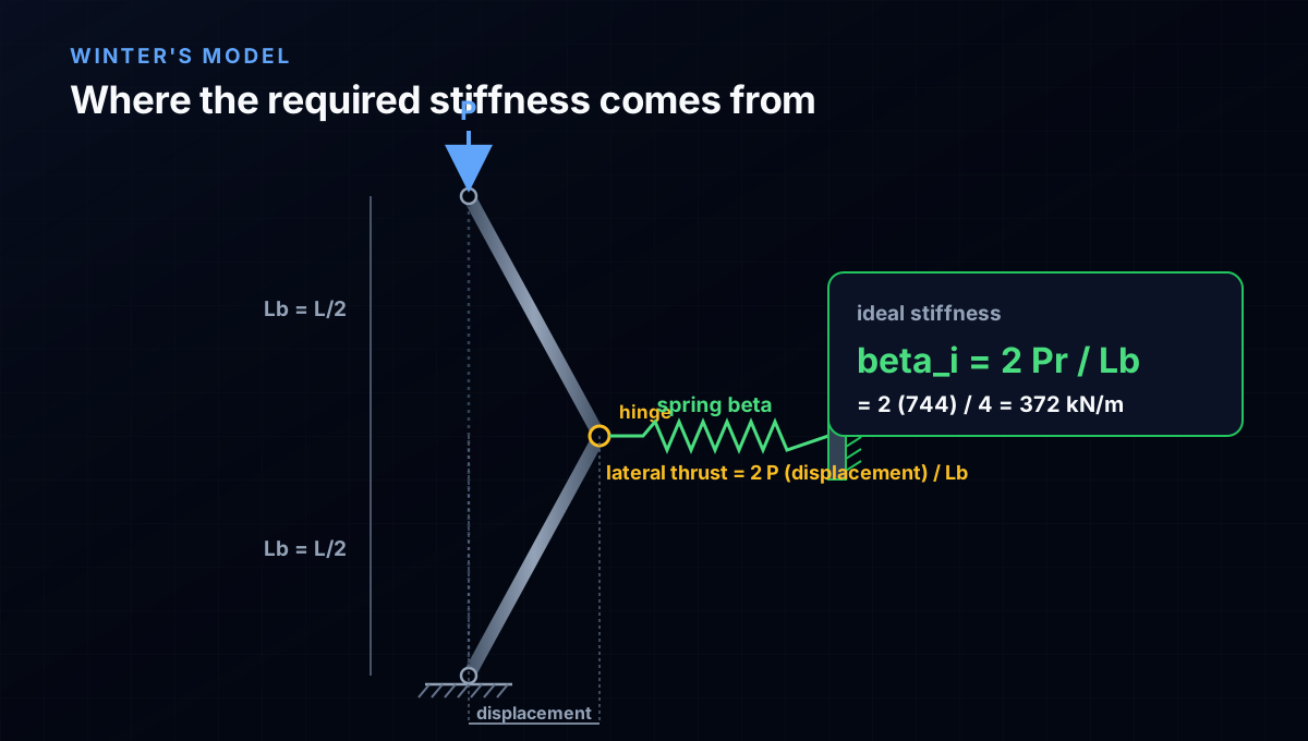
The classic way to find the stiffness a brace needs is George Winter's rigid-bar model, and it is worth doing by hand because it explains the code formula in one line. Replace the flexible column with two rigid bars, each of length Lb = L/2, pinned at the ends and hinged at the brace point, where a spring of stiffness beta holds the joint. Give the brace point a small sideways displacement and ask what spring stiffness is needed to keep the kinked column in equilibrium under the axial load P.
Taking moments on the upper rigid bar about its top pin, the axial force P acting through the displacement produces a lateral thrust at the brace of P·(displacement)/Lb. The lower bar contributes the same, so the spring must supply 2 P·(displacement)/Lb to hold the joint. Setting the spring force beta·(displacement) equal to that demand and cancelling the displacement gives the ideal stiffness:
beta_i = 2 Pr / Lb
This is the minimum spring stiffness that lets the column reach the load Pr. Provide less and the brace point drifts and the column buckles below the braced load; provide exactly beta_i and, in this idealised straight column, the braced load is just reached. For our IPE 300 the braced load is Pr = 4 Pe = 744 kN and Lb = 4 m, so beta_i = 2·744/4 = 372 kN/m. Notice what beta_i depends on: it grows with the load being braced and shrinks with the unbraced length. Higher loads and shorter segments need stiffer braces, which is exactly why closely spaced braces on heavily loaded columns are the ones that get governed by stiffness.
Measuring the ideal stiffness on the buckling engine
Winter's beta_i comes from a rigid-bar idealisation, so the honest question is whether a real elastic column agrees. We can check it directly. Model the IPE 300 in the CalcSteel finite-element buckling solver, attach a single lateral spring of stiffness beta at the midheight node, and run the linear buckling analysis for a sweep of beta from zero upward. Each run returns the elastic critical load Pcr; we plot it against Pe.
The result is the curve every bracing text draws but rarely computes:
- beta = 0 (no brace): Pcr = 1.00 Pe = 186 kN. Full-length buckling, as expected.
- beta = 0.25 beta_i (93 kN/m): Pcr = 1.80 Pe. A quarter of the ideal stiffness buys less than a third of the jump.
- beta = 0.50 beta_i (186 kN/m): Pcr = 2.57 Pe. Half the stiffness, well under half the benefit.
- beta = 0.75 beta_i (279 kN/m): Pcr = 3.31 Pe.
- beta = 1.00 beta_i (372 kN/m): Pcr = 4.00 Pe = 744 kN. The braced load is reached.
- beta = 2.00 beta_i (744 kN/m): Pcr = 4.00 Pe. Adding stiffness beyond beta_i does nothing for the critical load; the column already buckles between braces.
Two things fall out. First, the engine's saturation point, the smallest beta at which Pcr reaches 4 Pe, is 371.9 kN/m, against Winter's 371.9 kN/m: agreement to four significant figures. For a single central brace the rigid-bar formula is not just close, it is exact. Second, the approach to full bracing is slow and nonlinear. Half the ideal stiffness does not give you half the load; it gives you 2.57 Pe out of a possible 4. This is the quantitative reason a brace that is merely present, but soft, is nearly worthless: stiffness has to be almost all the way to beta_i before most of the benefit shows up.
Why ideal stiffness is never enough, and where the strength comes in
The sweep above was for a perfectly straight column. Real columns are not, and that is what turns the stiffness question into a strength question and forces the design stiffness above beta_i.
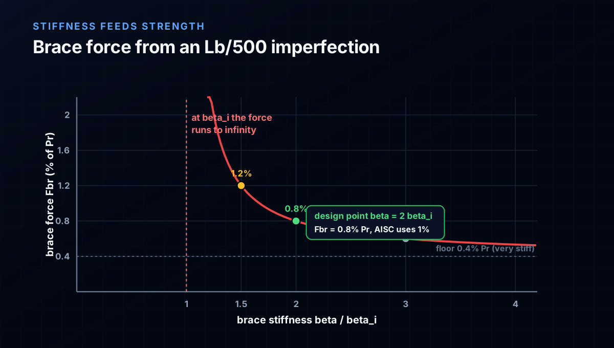
Give the column a small initial crookedness at the brace point, an out-of-straightness Delta_o that codes take as about Lb/500. Under load, the axial force acting through that offset amplifies it, and the brace has to hold the amplified displacement. Working the second-order equilibrium of Winter's model with the imperfection, the brace force at the design load comes out as:
F_br = beta_i · Delta_o / (1 - beta_i/beta)
Read what that fraction does. As the brace stiffness beta approaches the ideal beta_i, the denominator goes to zero and the required brace force goes to infinity. A brace with exactly the ideal stiffness would need infinite strength, because it lets the imperfection amplify without bound. That is the whole reason ideal stiffness is a floor you must clear with margin, not a target you sit on.
Add stiffness and the force drops fast. For Lb/500 crookedness (Delta_o = 8 mm here) at the braced load Pr = 744 kN:
- beta = 1.5 beta_i: total displacement 24 mm, brace force 8.9 kN = 1.2% Pr.
- beta = 2.0 beta_i: total displacement 16 mm, brace force 6.0 kN = 0.8% Pr.
- beta = 3.0 beta_i: brace force 4.5 kN = 0.6% Pr.
- beta = 10 beta_i: brace force 3.3 kN, approaching the floor of 0.4% Pr.
This is why the design rule is twice the ideal stiffness. At beta = 2 beta_i the initial 8 mm imperfection roughly doubles to 16 mm and the brace force settles at a manageable 0.8% of the column load. Halve the stiffness margin, to 1.5 beta_i, and both the displacement and the force run away. The stiffness requirement and the strength requirement are not independent: buying stiffness above the ideal is what keeps the strength demand small and finite.
How AISC 360 Appendix 6 packages the two requirements
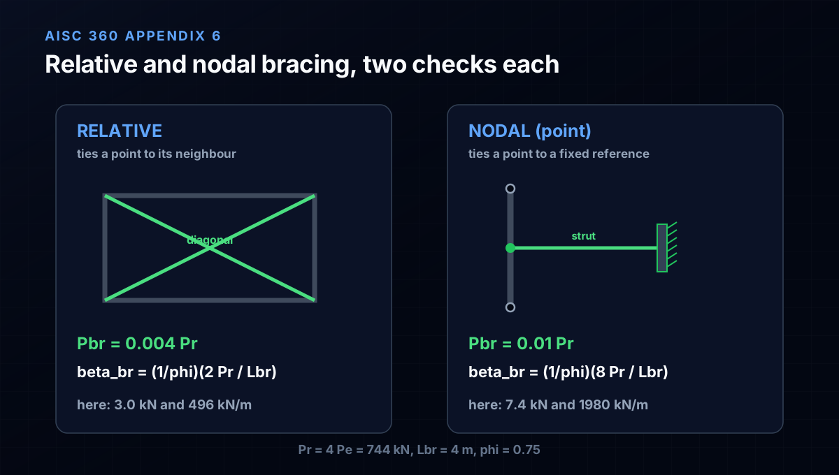
AISC 360 Appendix 6 turns exactly this model into two numbers per brace, a required strength and a required stiffness, and splits braces into two kinds by how they work.
Relative bracing controls one braced point relative to the adjacent one, the way a diagonal in an X-braced panel ties two floor levels together. Nodal (point) bracing holds a single point against an independent, effectively fixed reference, the way a horizontal strut ties a column to a stiff wall or a braced bay. Nodal braces work harder, because they cannot share the demand with a neighbour, so their coefficients are larger.
For column bracing the provisions are:
- Nodal: required strength Pbr = 0.01 Pr; required stiffness beta_br = (1/phi)(8 Pr / Lbr), with phi = 0.75.
- Relative: required strength Pbr = 0.004 Pr; required stiffness beta_br = (1/phi)(2 Pr / Lbr).
The strength coefficients, 1% and 0.4%, are the imperfection result you just saw, rounded for design. The stiffness coefficients carry the factor of two for the imperfection plus a further conservative allowance: the nodal 8 Pr/Lbr uses the many-brace limit rather than the 2 Pr/Lbr of a single brace, so it is safe no matter how many braces share the column. Applied to our IPE 300 with Pr = 744 kN and Lbr = 4 m, nodal bracing asks for a brace force of 7.4 kN and a stiffness of 1980 kN/m; relative bracing asks for 3.0 kN and 496 kN/m. The 1/phi in the stiffness term is deliberate: a brace that only just meets the ideal stiffness is not safe, so the code demands the stiffness with a resistance factor exactly as it would a strength.
The full check on one column
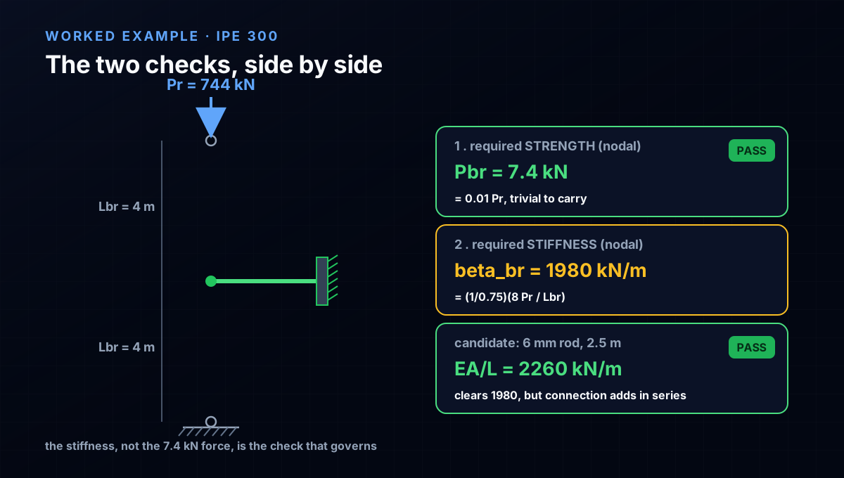
Pull it together on the IPE 300, braced at midheight to a stiff braced bay (a nodal brace), and carrying a required load equal to its braced capacity, Pr = 744 kN.
Step 1, the load the brace enables. Unbraced, the column's weak-axis Euler load is 186 kN. Bracing the midheight targets 4 Pe = 744 kN, so the brace has to be good enough to let the column reach 744 kN. Everything downstream uses Pr = 744 kN and Lbr = 4 m.
Step 2, the strength check. Nodal required brace strength Pbr = 0.01·744 = 7.4 kN. This is trivially small; almost any angle or rod, and its bolts, carry 7.4 kN without thinking. Strength is rarely the binding constraint for a compact brace.
Step 3, the stiffness check. Nodal required stiffness beta_br = (1/0.75)(8·744/4) = 1980 kN/m. Now compare a candidate: a 2.5 m long steel rod bracing to the stiff bay provides axial stiffness EA/L = (200 GPa)·A/2.5 m. To reach 1980 kN/m needs A = 1980·2.5/200e6 = 2.5e-5 m2, about 25 mm2, a 6 mm rod. That easily clears both checks. But swap the direct rod for a long, shallow diagonal, or add a slotted connection with slip, and the effective stiffness collapses while the strength stays fine, and the column quietly loses its bracing. The lesson is in which check nearly failed: not the 7.4 kN of force, but the 1980 kN/m of stiffness, and the connection sits inside that stiffness in series with the brace member.
Step 4, do not forget the reference. beta_br is the stiffness demanded at the braced point, which is the series combination of the brace member, its connections, and the flexibility of whatever it braces to. A perfect brace anchored to a wall that itself sways is only as stiff as the softest link. This is why lean-on and one-sided bracing schemes need the reference checked, not assumed rigid.
Beams need it too, and not every brace is a diagonal
Everything so far was a column bracing against flexural buckling, but the same two requirements govern beam bracing against lateral-torsional buckling, with one addition: a beam brace must control twist, not just lateral movement of one flange. A brace that holds the compression flange laterally braces the beam; one that holds only the tension flange, or the centroid, may let the section roll and does little. Beam bracing in Appendix 6 comes in the same relative and nodal flavours, plus torsional bracing (a stiff cross-member or a connected slab) that restrains twist directly, and the stiffness formulas carry the same structure, an ideal stiffness doubled for imperfection.
It is also worth naming the brace arrangements, because they change what the stiffness is measured against. Relative braces (X-bracing, chevrons) tie a point to its neighbour. Nodal braces (a strut to a rigid bay) tie a point to a fixed reference. Continuous bracing (a deck or wall attached along the member) provides a distributed stiffness per unit length. And lean-on systems, where several columns share one braced bay, add all the leaning columns' loads into the Pr the bracing must resist, a common and dangerous place to under-size the reference. If you want the wider catalogue of lateral systems and where each fits, see the companion piece on steel bracing systems; this article is about what any one of those braces must deliver to count.
Six ways bracing quietly fails
None of these throws an error in analysis. Each leaves a brace that looks fine on the drawing and does not do its job.
- Sizing the brace for strength only. The 1% force is easy to pass and tells you almost nothing. The stiffness check is the one that governs, and it is the one people skip.
- Ignoring connection flexibility. beta_br is the stiffness at the braced point. A stiff brace member on a slotted, slipping, or long-bolt-grip connection can deliver a fraction of its bare EA/L. The connection adds in series and often dominates.
- Assuming the reference is rigid. A nodal brace is only as good as what it braces to. Anchor to a wall or bay that itself deflects and the effective stiffness is the series combination, not the brace alone.
- Bracing the wrong point or the wrong flange. A column brace off the buckling axis, or a beam brace on the tension flange, restrains a movement the member was not going to make. The buckled shape decides where a brace helps.
- Forgetting lean-on loads. When leaning columns hang their stability on one braced bay, the bracing must resist the sum of their loads. Sizing it for one column is a classic collapse.
- Treating a soft brace as full bracing. Below the ideal stiffness the column does not reach the braced load; it lands short, as the sweep showed (half the stiffness gives 2.57 Pe, not 4). A present-but-soft brace is not partial credit you can lean on without checking the actual reduced capacity.
Try it: watch the load follow the unbraced length
The quickest way to feel why bracing pays is to change the unbraced length yourself and watch the buckling load respond. Open the column buckling calculator below, enter the IPE 300 (or any section), and set the unbraced length to the full 8 m: you will see the weak-axis critical load near 186 kN. Now halve the length to 4 m, the value a midheight brace delivers, and the load jumps to roughly 744 kN, the fourfold increase this whole article is about. The calculator is doing the pi^2 EI/L^2 that a brace lets you invoke with the shorter L.
That is the honest division of labour. The calculator gives you the braced and unbraced capacities in seconds; Appendix 6 tells you whether the brace you drew is actually stiff enough and strong enough to earn the shorter length. From here the natural next reads are Euler buckling, where the pi^2 EI/L^2 comes from, and torsional-flexural buckling, the mode a brace on the wrong axis fails to stop.
End conditions (buckling case)
Pinned – Pinned
Cross-section
Slenderness KL/r
134.7
limit 200 · OK
Euler Pcr (elastic)
310.7 kN
Fe = 108.9 MPa
AISC 360 φcPn
245.2 kN
Fcr = 95.5 MPa · elastic
NBR 8800 Nc,Rd
247.7 kN
χ = 0.382 · λ₀ = 1.52
Code vs code — same column
Nc,Rd / φcPn = 1.010
Both codes share the 0.658 / 0.877 buckling curve — the ~1% gap is purely φc = 0.90 (AISC) vs 1/γa1 = 0.909 (NBR).
Demand check — Nd = 150 kN
Step-by-step derivation — live for YOUR column
IPE 200 · L = 3 m · K = 1 · fy = 250 MPa
- 1
Slenderness ratio
λ = K·L/r = 1 × 3000 / 22.28 mm
λ = 134.7 (≤ 200 ✓)
- 2
Euler elastic buckling stress and load
Fe = π²E/λ² = π² × 200,000 / 134.7² · Pcr = Fe·A = Fe × 2854 mm²
Fe = 108.9 MPa · Pcr = 310.7 kN
- 3
Buckling regime (AISC E3)
4.71·√(E/fy) = 4.71·√(200,000/250) = 133.2 < λ = 134.7
elastic buckling → use E3-3 (0.877·Fe)
Elastic range: capacity no longer depends on fy — only geometry (r, K, L) helps.
- 4
AISC 360 critical stress and design capacity
Fcr = 0.877 · Fe = 0.877 × 108.9 = 95.5 MPa · φcPn = 0.9 × Fcr × A
Pn = 272.5 kN · φcPn = 245.2 kN
- 5
NBR 8800 reduction factor and design capacity
λ₀ = √(fy/Fe) = 1.515 > 1.5 → χ = 0.877/λ₀² = 0.382 · Nc,Rd = χ·A·fy/1.1
Nc,Rk = 272.5 kN · Nc,Rd = 247.7 kN
Same 0.658/0.877 curve as AISC — the ~1% difference is φc = 0.90 vs 1/γa1 = 0.909.
Sections that work — 3 lightest of 612 catalog profiles carrying Nd = 150 kN at L = 3 m, K = 1
| Section | kg/m | φcPn (kN) | Nc,Rd (kN) | Util. | |
|---|---|---|---|---|---|
| lightestSHS 80x4 | 9.2 | 164 | 166 | 91% | |
| HSS 76x76x4.8 | 9.9 | 165 | 167 | 91% | |
| CHS 88.9x5 | 10.3 | 172 | 174 | 87% |
Pass criterion: φcPn ≥ Nd (AISC 360 LRFD) AND Nc,Rd ≥ Nd (NBR 8800) AND KL/r ≤ 200, using each section's tabulated-mass area and minimum radius of gyration.
Buckling curve — IPE 200, fy = 250 MPa
Capacity of IPE 200 by unbraced length — K = 1, fy = 250 MPa
| L (m) | KL/r | Pcr Euler (kN) | φcPn AISC (kN) | Nc,Rd NBR (kN) | Regime |
|---|---|---|---|---|---|
| 1 | 45 | 2,796 | 577 | 583 | inelastic |
| 2 | 90 | 699 | 419 | 423 | inelastic |
| 3◀ yours | 135 | 311 | 245 | 248 | elastic |
| 4 | 180 | 175 | 138 | 139 | elastic |
| 5 | 224 ⚠ | 112 | 88 | 89 | elastic |
| 6 | 269 ⚠ | 78 | 61 | 62 | elastic |
| 7 | 314 ⚠ | 57 | 45 | 45 | elastic |
| 8 | 359 ⚠ | 44 | 34 | 35 | elastic |
| 9 | 404 ⚠ | 35 | 27 | 28 | elastic |
| 10 | 449 ⚠ | 28 | 22 | 22 | elastic |
Sources
- 1.AISC 360-22, Specification for Structural Steel Buildings, Appendix 6 (Member and System Stability Bracing) and its Commentary
- 2.Winter, G., Lateral Bracing of Columns and Beams, Journal of the Structural Division, ASCE (1958); and Yura, J.A., Fundamentals of Beam Bracing, AISC Engineering Journal (2001)
- 3.Salmon, Johnson and Malhas, Steel Structures: Design and Behavior, chapter on frames and bracing (stability bracing requirements)
- 4.Timoshenko and Gere, Theory of Elastic Stability, articles on buckling of columns with intermediate elastic supports
Try CalcSteel for free
Model, analyze and design steel structures in your browser. No install, no signup.
Open the 3D editor