Torsional-Flexural Buckling: the Mode That Governs Channels and Angles, Not the Euler One
A channel or an angle in compression does not have to bend to fail. It can twist, or bend and twist at once, at a load well below the Euler value. This guide shows where that mode comes from, how the AISC 360 Chapter E4 method turns the shear centre offset into a real number, and a worked cold-formed lipped channel where torsional-flexural buckling drops the design strength 32 percent below the Euler weak-axis answer, with the whole check reproduced by the CalcSteel column engine.
Key takeaways
- Euler buckling assumes the column bends and does not twist. That is true only for doubly symmetric shapes like an I or a box. For a channel, a tee or an angle, the shear centre sits off the centroid, so axial load twists the section and a torsional-flexural mode can govern instead.
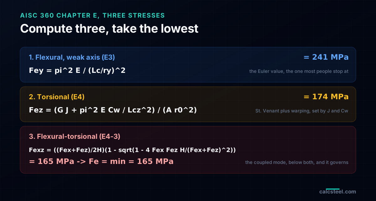
- AISC 360 gives you three elastic stresses to compute and one rule: take the lowest. Fey is the weak-axis Euler stress from E3, Fez is the torsional stress from E4, and Fexz is the flexural-torsional stress from E4-3 that couples bending about the axis of symmetry with twist. Fe equals the minimum, and it feeds the same Fcr curve as Euler.
- In the worked lipped channel, 200 by 90 by 20 by 3 mm at a 3 m pinned length, the Euler weak-axis stress is Fey equals 241 MPa but the flexural-torsional stress is Fexz equals 165 MPa. The torsional-flexural mode governs, and the design strength drops from 212 to 160 kN.
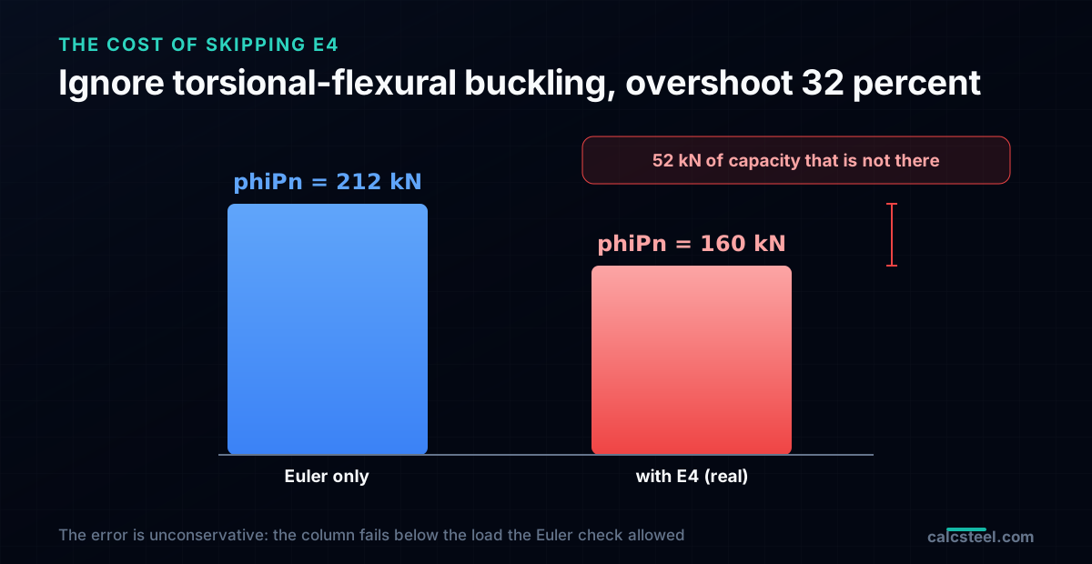
- Ignoring E4 and stopping at Euler overestimates that column by 32 percent, and the error is unconservative: the phantom 52 kN of capacity is not there, so the column fails below the load the Euler check allowed. For thin-walled open sections this is the difference between a pass and a real failure.
- Every number here is hand calculated with the AISC 360 E4 method and reproduced by the CalcSteel column engine, which runs E3 and E4 together and returns Fe equals 165 MPa, Fcr equals 144 MPa and phiPn equals 160 kN for this section, matching the hand check to the decimal.
Why the Euler formula is only part of the answer
You size a compression member, pick the weak axis, compute the Euler stress from the slenderness, run it through the column curve, and read a capacity. For a wide flange or a hollow section that is the whole story. For a channel, a structural tee, or an angle, it is not, and the member can fail at a load well below the number you just wrote down. Nothing was miscalculated. The load path found a mode the Euler formula never contained: the section twisted.
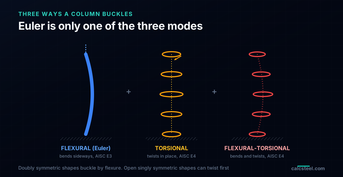
The Euler buckling formula describes one failure: the column bows sideways in pure bending, with every cross section staying flat and untwisted. That assumption is exact only when the shear centre and the centroid are the same point, which happens for doubly symmetric shapes, an I, a box, a solid bar. The moment the shear centre moves off the centroid, and it moves for every open singly symmetric or asymmetric section, axial load through the centroid starts to twist the member. Now there are three ways to buckle, not one: bend, twist, or do both at once. AISC 360 calls the last two torsional and flexural-torsional buckling, and for channels and angles they routinely give a lower strength than the Euler mode.
This guide turns that mode into a number. Every stress here is computed with the AISC 360 Chapter E method and reproduced by the CalcSteel column engine, which runs the flexural and the torsional-flexural checks together. We wrote it for three readers. If you are a student, this is the buckling case your course names in one slide and never works out. If you are a practising engineer or a freelance calculista, jump to the worked channel and the length chart, where a mode you might have skipped removes a third of the capacity. And if you just want the rule: for anything open that is not doubly symmetric, the Euler check is a ceiling, not the answer, and you have to run E4 to find the floor.
The three modes, and when each one wins
Start with the modes themselves, because the whole method is just a competition between them. A straight column under axial compression can lose stability in three distinct shapes.
Flexural buckling, the Euler mode
The column bows about one of its principal axes, staying straight in torsion. Each cross section translates sideways but does not rotate. This is the classic Euler case, one for each axis, and the elastic stress is Fe equals pi squared E over the slenderness squared. For a doubly symmetric section it is the only mode that matters, because there is no coupling to twist.
Torsional buckling, the pure twist
The column rotates about its longitudinal axis, every cross section twisting like a key in a lock, with no sideways movement. It is resisted by two stiffnesses working in parallel: the St. Venant torsional stiffness G times J, and the warping stiffness E times Cw. Pure torsional buckling governs only for special doubly symmetric shapes with very low torsional stiffness, a cruciform or a very short heavy column, but it is the ingredient the flexural-torsional mode is built from.
Flexural-torsional buckling, the coupled mode
The column bends and twists at the same time, in a single coupled shape. This is the mode that governs channels, tees, and angles. It exists because the shear centre is offset from the centroid: bending about the axis of symmetry can no longer happen without twist, so the two deformations lock together and buckle as one, at a load below either acting alone. The buckling about the other principal axis, the one with no symmetry to couple, stays a pure Euler mode. So the real competition for a channel is short: weak-axis Euler on one side, flexural-torsional on the other, lowest wins.
That is the entire logic of AISC 360 Chapter E. Compute the Euler stress for each axis, compute the torsional stress, combine the coupled ones, and take the minimum. The rest is finding the section properties that feed it.
Where the twist comes from: the shear centre
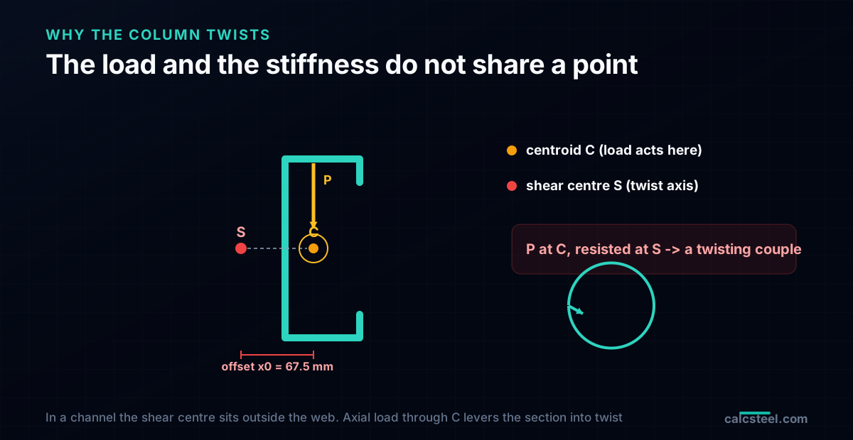
The coupling has one cause, and it is geometric. Every section has two special points. The centroid is where axial load acts, the balance point of the area. The shear centre is where transverse load must pass to bend the section without twisting it, the point the section rotates about when it does twist. For a doubly symmetric shape the two points coincide, and axial load, acting at the centroid, passes through the shear centre and produces no twist. That is why an I-section obeys Euler.
For a channel the shear centre lies outside the section entirely, on the far side of the web from the flanges. For a tee it sits at the junction of flange and stem. For an angle it sits at the heel, where the two legs meet. In every case it is a real distance away from the centroid, and that distance, called x0 in the AISC equations, is what breaks the Euler assumption. Axial load still acts at the centroid, but the section's resistance to twist is organised about the shear centre, so the load and the stiffness no longer share a point. The offset turns the axial force into a lever that feeds twist, exactly the way an off-centre push on a door feeds rotation about the hinge.
This is the same offset that makes an open section twist under transverse load, the subject of the shear centre and torsion guide. There the offset invents torsion from a load you did not think was eccentric. Here it invents a buckling mode from a load that is perfectly axial. Same geometry, two different failures. The larger the offset x0 and the smaller the torsional stiffness G times J, the more the section wants to twist, and the lower the flexural-torsional load falls below Euler.
The AISC 360 Chapter E method, stress by stress
AISC 360 handles this in Chapter E, and once the section properties are in hand it is three formulas and a minimum. Work in consistent units, here E equals 200 GPa and G equals 77 GPa for steel, with lengths as the effective lengths Lc equals K times L.
Step 1: the flexural stresses (E3)
The two Euler stresses, one per principal axis: Fex equals pi squared E over (Lcx over rx) squared and Fey equals pi squared E over (Lcy over ry) squared, with rx and ry the radii of gyration. For a channel Fey, about the weak axis, is the pure flexural competitor. Fex, about the axis of symmetry, does not act alone: it goes into the coupled mode.
Step 2: the torsional stress (E4)
The stress that would cause pure twist:
Fez equals ( G J plus pi squared E Cw over Lcz squared ) divided by ( A times r0 squared )
where J is the St. Venant torsional constant, Cw is the warping constant, A is the area, and r0 is the polar radius of gyration about the shear centre, r0 squared equals x0 squared plus y0 squared plus (Ix plus Iy) over A. Read Fez as how hard the section resists twisting, set almost entirely by J and Cw. Thin open walls have a tiny J, because J scales with thickness cubed, so their Fez is low, and that is what pulls the coupled mode down.
Step 3: the coupled stress and the minimum (E4-3)
For a singly symmetric section, bending about the axis of symmetry, here Fex, couples with the twist Fez into the flexural-torsional stress:
Fexz equals ( (Fex plus Fez) over 2H ) times ( 1 minus square root of ( 1 minus 4 Fex Fez H over (Fex plus Fez) squared ) )
with the flexural constant H equals 1 minus x0 squared over r0 squared, which measures how far the shear centre sits from the centroid. Then the governing elastic stress is simply Fe equals the minimum of Fey and Fexz. That Fe feeds the ordinary column curve, Fcr equals 0.658 to the power (Fy over Fe) times Fy when Fe is at least 0.44 Fy, and Fcr equals 0.877 Fe when the column is slender, exactly as in the Euler check. The design strength is phiPn equals 0.90 times Fcr times A. Nothing about the column curve changes. Only the elastic stress you feed it does.
Worked example: a lipped channel where the twist wins
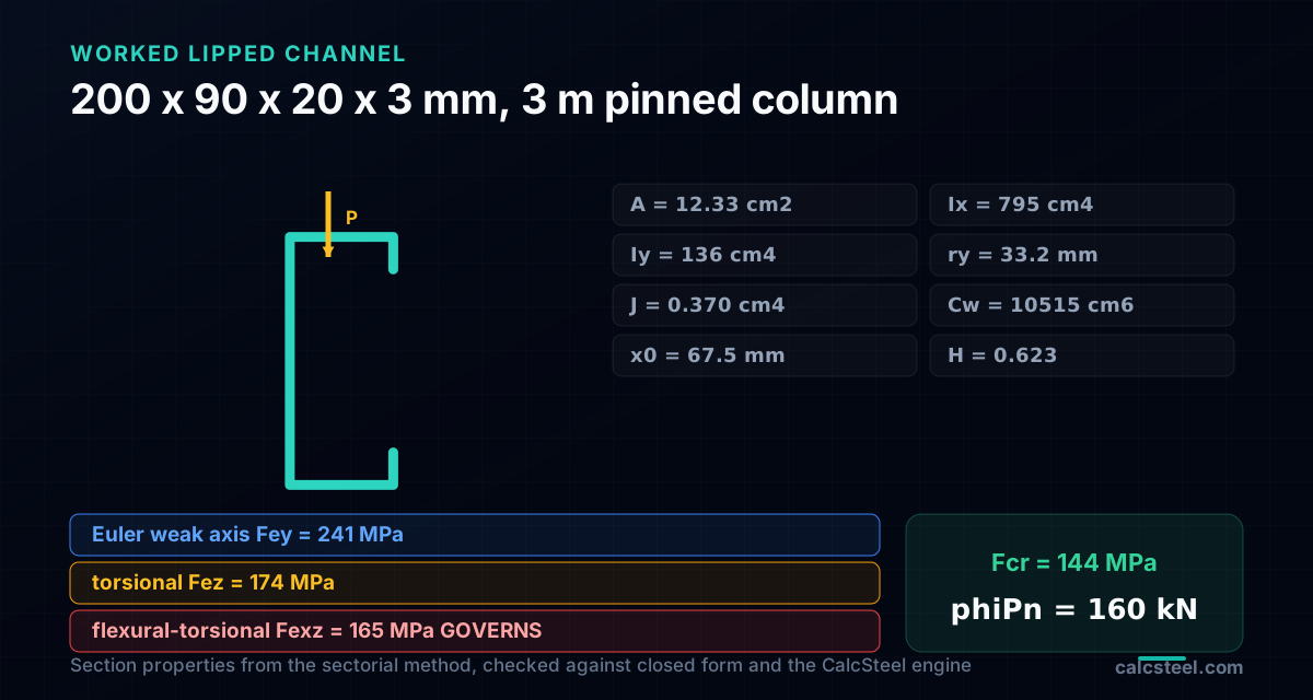
Put the method on a real section. Take a cold-formed lipped channel, 200 by 90 by 20 by 3 mm, a common stud or rack upright, used as a pinned column 3 m long, K equals 1 on every axis, steel Fy equals 350 MPa. Its section properties, computed with the thin-wall sectorial method and cross checked against closed-form formulas and the CalcSteel geometry engine, are:
- Area A equals 12.33 square cm, radii of gyration rx equals 80.3 mm and ry equals 33.2 mm.
- Torsional constant J equals 0.370 cm to the fourth, warping constant Cw equals 10515 cm to the sixth.
- Shear centre offset x0 equals 67.5 mm, polar radius r0 equals 110.0 mm, flexural constant H equals 0.623.
Step 1: the flexural stresses
The weak-axis slenderness is Lcy over ry equals 3000 over 33.2 equals 90.5, so the Euler weak-axis stress is Fey equals pi squared times 200000 over 90.5 squared equals 241 MPa. About the axis of symmetry, Fex equals 1414 MPa, far higher because rx is large. A designer who checked only the weak axis would stop here, at 241 MPa.
Step 2: the torsional stress
Feed the properties into Fez equals ( G J plus pi squared E Cw over Lcz squared ) over ( A r0 squared ), with G equals 77 GPa, J equals 0.370 cm to the fourth, E equals 200 GPa, Cw equals 10515 cm to the sixth, Lcz equals 3 m, A equals 12.33 square cm and r0 equals 110 mm. The result is Fez equals 174 MPa, already lower than Fey, because the 3 mm wall makes J small and the warping term cannot make it up.
Step 3: the coupled stress
Feed Fex equals 1414, Fez equals 174 and H equals 0.623 into the E4-3 formula and the flexural-torsional stress is Fexz equals 165 MPa. Now compare: Fe equals the minimum of Fey equals 241 and Fexz equals 165, so Fe equals 165 MPa and the flexural-torsional mode governs. The column does not bend to failure, it bends and twists, at a stress a third below the Euler answer.
Step 4: the strength
Since Fe equals 165 is above 0.44 Fy equals 154, use the inelastic curve: Fcr equals 0.658 to the power (350 over 165) times 350 equals 144 MPa. The nominal strength is Pn equals Fcr times A equals 178 kN, and the design strength is phiPn equals 0.90 times 178 equals 160 kN. The CalcSteel column engine, running E3 and E4 together on this section, returns Fe equals 165 MPa, Fcr equals 144 MPa and phiPn equals 160 kN, matching the hand calculation to the decimal.
How the two modes trade over length
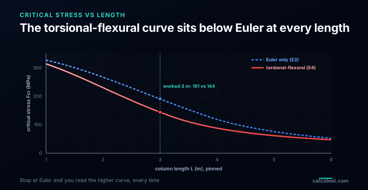
One worked point is a snapshot. The useful picture is how the modes trade as the column gets longer, because the answer to which one governs is not always the same. Hold the section fixed and sweep the pinned length, comparing the critical stress the Euler check alone would give against the true stress with E4 included.
- L equals 1 m: Euler-only Fcr equals 327 MPa, true Fcr equals 314 MPa. The stub is stocky, both modes are near yield, and the gap is small.
- L equals 2 m: Euler-only 267 MPa, true 230 MPa. The twist is already taking 14 percent.
- L equals 3 m (the worked column): Euler-only 191 MPa, true 144 MPa. A 25 percent gap in stress, a 32 percent gap in strength once the area is applied and the two curves diverge.
- L equals 4 m: Euler-only 119 MPa, true 88 MPa.
- L equals 5 m: Euler-only 76 MPa, true 62 MPa.
For this wide-flanged lipped channel the flexural-torsional curve sits below the Euler curve at every length, so the twist governs across the whole practical range. That is not a universal rule, it is what this geometry does: the wide flanges make the weak-axis Euler stress high, while the thin wall keeps the torsional stiffness low, so the coupled mode wins everywhere. A narrower, thicker channel would show a crossover, where torsional-flexural governs the shorter columns and Euler takes over the long ones. Either way, the lesson is the same: you cannot know which curve you are on until you have computed both.
What it costs to stop at Euler
The gap is not academic, and it points the dangerous way. At the worked 3 m length the Euler weak-axis check, taken alone, gives a critical stress of 191 MPa and a design strength of 212 kN. The full check, with the flexural-torsional mode, gives 144 MPa and 160 kN. The difference is 52 kN, a 32 percent overestimate, and it is unconservative: the Euler-only number is too high, so a column designed and accepted against it would be loaded to a demand the real section cannot carry. It would buckle by twisting at a load the calculation said was safe.
This is what makes torsional-flexural buckling worth naming. Most detailing errors are conservative or obvious. This one is neither. The applied load is honestly axial, the slenderness is honestly computed, the Euler formula is honestly applied, and the answer is still wrong by a third, because the formula answered the wrong question. There is no warning in the numbers you did compute. The only signal is the shape of the section: open, singly symmetric, shear centre off the centroid. When you see that, the Euler stress is an upper bound, and you owe the section an E4 check before you trust it.
The same discipline carries into a beam-column, where the axial term of the combined axial and bending interaction uses this very Pn. If Pn was computed from the Euler mode alone, the interaction inherits the same 32 percent error, and every load combination on that member is checked against a capacity that is not there.
Which sections need the E4 check, and which do not
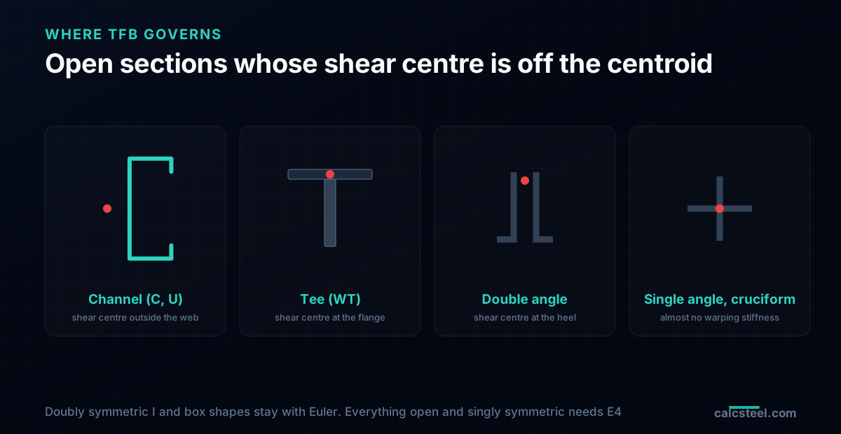
You do not run E4 on everything. The mode only bites when the shear centre is off the centroid, so a quick look at the section tells you whether it is on the table.
Channels, C and U
The worked case. The shear centre sits outside the web, the offset x0 is large, and thin channels have little torsional stiffness. Flexural-torsional buckling is a live check on every channel column, and often governs.
Tees, WT and structural tees
The shear centre lies on the flange, far from the centroid down in the stem, and the stem contributes almost no warping stiffness, so Cw is tiny and Fez is low. Tees are one of the classic sections where the torsional-flexural mode governs across most lengths.
Angles, single and double
Single angles buckle about their weak principal axis with strong flexural-torsional coupling, which is why AISC gives them a dedicated simplified method in Section E5 for the common case of an angle loaded through one leg. Double angles, a staple of trusses and bracing, are singly symmetric and pry the coupled mode through both legs. Both need the check, and the title of this guide is not an accident: for angles and channels the twist is the rule, not the exception.
Where you can skip it
Doubly symmetric shapes, wide flanges, hollow structural sections, boxes, pipes, have their shear centre at the centroid, so x0 is zero, the coupling vanishes, and the flexural-torsional stress can never fall below the flexural one. For them the Euler check is the whole check. Cruciforms and other thin open shapes are the opposite extreme, with warping stiffness so low that pure torsional buckling can govern on its own. Cold-formed members carry one more layer, local and distortional buckling of the thin walls, which the cold-formed steel framing rules handle as a separate effective-section check on top of the global mode shown here.
Five ways the twist slips past a check
Each of these makes a column pass on paper while the real section is over its true buckling load. None of them throws an error, which is exactly why torsional-flexural buckling keeps surprising careful engineers.
- Checking only the weak axis. The biggest one. Taking the smaller of Fex and Fey and stopping there assumes the section cannot twist. For a channel or a tee that skips the mode that governs, and overstates the strength by the full gap, here 32 percent.
- Using r0 as an ordinary radius of gyration. The r0 in Fez is the polar radius about the shear centre, r0 squared equals x0 squared plus rx squared plus ry squared, not sqrt of (Ix plus Iy over A) about the centroid. Dropping the x0 squared term inflates Fez and hides the twist.
- Forgetting the warping constant Cw, or reading it wrong. Fez needs both G J and E Cw. Setting Cw to zero, or pulling a value for the wrong axis, can move Fez by tens of percent. For a tee Cw is nearly zero and that is the point, not a rounding error.
- Taking Kz equal to Kx. The torsional effective length Kz depends on how the ends are restrained against twist and warping, which is often different from the flexural restraint. A pin that stops translation may still allow warping, and Kz is not automatically 1.
- Trusting a section table's Euler-only capacity for an open shape. Some quick tables and spreadsheets report a compression capacity from KL over r alone. For a channel, tee or angle that number is the Euler ceiling, not the design strength, and it needs the E4 check layered on before you use it.
Check it live, both modes at once
The fastest way to feel the mode is to watch the two stresses trade as you change the section and the length. The calculator below is the CalcSteel column buckling tool, free and with no login for the maths. It runs the AISC 360 Chapter E check, the flexural stresses from E3 and the torsional-flexural stress from E4, and reports the governing Fe, the critical stress Fcr, and the design strength, for the section and effective lengths you set. Point it at the worked lipped channel and it returns Fe equals 165 MPa and phiPn equals 160 kN, the same numbers hand calculated above.
Set a doubly symmetric wide flange and the torsional-flexural stress climbs out of reach, the flexural mode governs, and you are back to a pure Euler check. Switch to a channel, a tee or an angle and watch Fexz drop below Fey and take over. That single toggle is the whole lesson of this guide made interactive: the shape of the section decides whether Euler is the answer or just the ceiling.
In a real model the check multiplies across every compression member, every effective length, and every load combination, with the torsional-flexural mode live on every open section and the flexural mode alone on the doubly symmetric ones. That is what the CalcSteel column engine automates, and where you still bring the judgement: the end restraint against warping, the bracing that shortens Lcz, or a section too thin to trust without the cold-formed local check. Take the same member into the effective length and K factor workflow, where the Lc that feeds every one of these stresses is decided.
End conditions (buckling case)
Pinned – Pinned
Cross-section
Slenderness KL/r
134.7
limit 200 · OK
Euler Pcr (elastic)
310.7 kN
Fe = 108.9 MPa
AISC 360 φcPn
245.2 kN
Fcr = 95.5 MPa · elastic
NBR 8800 Nc,Rd
247.7 kN
χ = 0.382 · λ₀ = 1.52
Code vs code — same column
Nc,Rd / φcPn = 1.010
Both codes share the 0.658 / 0.877 buckling curve — the ~1% gap is purely φc = 0.90 (AISC) vs 1/γa1 = 0.909 (NBR).
Demand check — Nd = 150 kN
Step-by-step derivation — live for YOUR column
IPE 200 · L = 3 m · K = 1 · fy = 250 MPa
- 1
Slenderness ratio
λ = K·L/r = 1 × 3000 / 22.28 mm
λ = 134.7 (≤ 200 ✓)
- 2
Euler elastic buckling stress and load
Fe = π²E/λ² = π² × 200,000 / 134.7² · Pcr = Fe·A = Fe × 2854 mm²
Fe = 108.9 MPa · Pcr = 310.7 kN
- 3
Buckling regime (AISC E3)
4.71·√(E/fy) = 4.71·√(200,000/250) = 133.2 < λ = 134.7
elastic buckling → use E3-3 (0.877·Fe)
Elastic range: capacity no longer depends on fy — only geometry (r, K, L) helps.
- 4
AISC 360 critical stress and design capacity
Fcr = 0.877 · Fe = 0.877 × 108.9 = 95.5 MPa · φcPn = 0.9 × Fcr × A
Pn = 272.5 kN · φcPn = 245.2 kN
- 5
NBR 8800 reduction factor and design capacity
λ₀ = √(fy/Fe) = 1.515 > 1.5 → χ = 0.877/λ₀² = 0.382 · Nc,Rd = χ·A·fy/1.1
Nc,Rk = 272.5 kN · Nc,Rd = 247.7 kN
Same 0.658/0.877 curve as AISC — the ~1% difference is φc = 0.90 vs 1/γa1 = 0.909.
Sections that work — 3 lightest of 612 catalog profiles carrying Nd = 150 kN at L = 3 m, K = 1
| Section | kg/m | φcPn (kN) | Nc,Rd (kN) | Util. | |
|---|---|---|---|---|---|
| lightestSHS 80x4 | 9.2 | 164 | 166 | 91% | |
| HSS 76x76x4.8 | 9.9 | 165 | 167 | 91% | |
| CHS 88.9x5 | 10.3 | 172 | 174 | 87% |
Pass criterion: φcPn ≥ Nd (AISC 360 LRFD) AND Nc,Rd ≥ Nd (NBR 8800) AND KL/r ≤ 200, using each section's tabulated-mass area and minimum radius of gyration.
Buckling curve — IPE 200, fy = 250 MPa
Capacity of IPE 200 by unbraced length — K = 1, fy = 250 MPa
| L (m) | KL/r | Pcr Euler (kN) | φcPn AISC (kN) | Nc,Rd NBR (kN) | Regime |
|---|---|---|---|---|---|
| 1 | 45 | 2,796 | 577 | 583 | inelastic |
| 2 | 90 | 699 | 419 | 423 | inelastic |
| 3◀ yours | 135 | 311 | 245 | 248 | elastic |
| 4 | 180 | 175 | 138 | 139 | elastic |
| 5 | 224 ⚠ | 112 | 88 | 89 | elastic |
| 6 | 269 ⚠ | 78 | 61 | 62 | elastic |
| 7 | 314 ⚠ | 57 | 45 | 45 | elastic |
| 8 | 359 ⚠ | 44 | 34 | 35 | elastic |
| 9 | 404 ⚠ | 35 | 27 | 28 | elastic |
| 10 | 449 ⚠ | 28 | 22 | 22 | elastic |
Sources
- 1.AISC 360-22 Specification for Structural Steel Buildings, Chapter E (E3 Flexural Buckling, E4 Torsional and Flexural-Torsional Buckling, E5 Single Angle Compression Members)
- 2.Salmon, Johnson and Malhas, Steel Structures: Design and Behavior, chapter on torsional and torsional-flexural buckling of columns
- 3.AISC Design Guide 9, Torsional Analysis of Structural Steel Members (shear centre, warping constant Cw, torsional constant J)
- 4.Yu and LaBoube, Cold-Formed Steel Design, torsional-flexural buckling of open thin-walled sections
- 5.ABNT NBR 8800 and NBR 14762, design of steel and cold-formed steel structures, flexural-torsional buckling provisions
Try CalcSteel for free
Model, analyze and design steel structures in your browser. No install, no signup.
Open the 3D editor