Cold-Formed Steel Framing: Design a Stud, Joist & Header
Cold-formed steel framing design for studs, joists and headers: verified FEM demand for light steel framing. Run the free beam calculator now.
Key takeaways
- Cold-formed steel framing builds real buildings from thin steel sheet (~0.8-3 mm) roll-formed cold into C-studs, C-joists and U-tracks, screwed into wall, floor and roof panels.
- Thinness changes the physics: members buckle locally, distortionally and globally before they yield, so design uses an effective section (AISI S100/DSM, Eurocode 3-1-3, NBR 14762, AS/NZS 4600) - never the gross section.
- Serviceability usually governs: across every worked example the members had big strength reserves while deflection (L/300 floors, L/240 wind walls) and floor vibration sized them.
- Details decide capacity: web crippling and bearing stiffeners at supports, bridging and blocking against twist, and realistic end restraint (a screwed clip lives between a pin and a fixity) are the design.
- CalcSteel's real FEM engine returns exact elastic demand for free - reactions, shear, moment and deflection matched to closed-form theory to three decimals - with the effective-width / DSM capacity check as the paired next step.
From a single stud to a whole building
Cold-formed steel framing — also called light steel framing or LSF — now frames whole houses, schools and mid-rise buildings out of steel sheet only a few millimetres thick. The sheet is roll-formed cold into slender C-shaped studs and joists that are lighter than the equivalent timber, dimensionally perfect straight off the line, non-combustible, and immune to rot and termites. What looks like a fragile channel becomes, once screwed into panels and braced, a complete load path from roof to foundation.
This pillar walks that path from a single stud to a full wall and floor. Every reaction, shear, moment and deflection you will read here was computed in the CalcSteel FEM engine and checked against closed-form theory to three decimals — no hand-waving, no invented numbers. And because the tool is browser-native and genuinely free, you can drive the same calculator yourself while you read: set a span, a load and a cold-formed section, and read V, M and deflection instantly.
We wrote it for three readers at once:
- Engineering students who want to see how thin-walled section theory turns into a real member design.
- Practising engineers who need a fast, verified way to get elastic demand on a stud, joist or header before running the code capacity check.
- Builders and architects researching whether light steel framing is right for their project — and how it actually goes together.
One honest caveat up front: the engine returns the elastic demand — reactions, shear, moment and deflection. It does not compute the cold-formed capacity; that effective-width / Direct Strength Method check is the next step, and we point to exactly where it belongs at each stage.
What cold-formed steel framing is
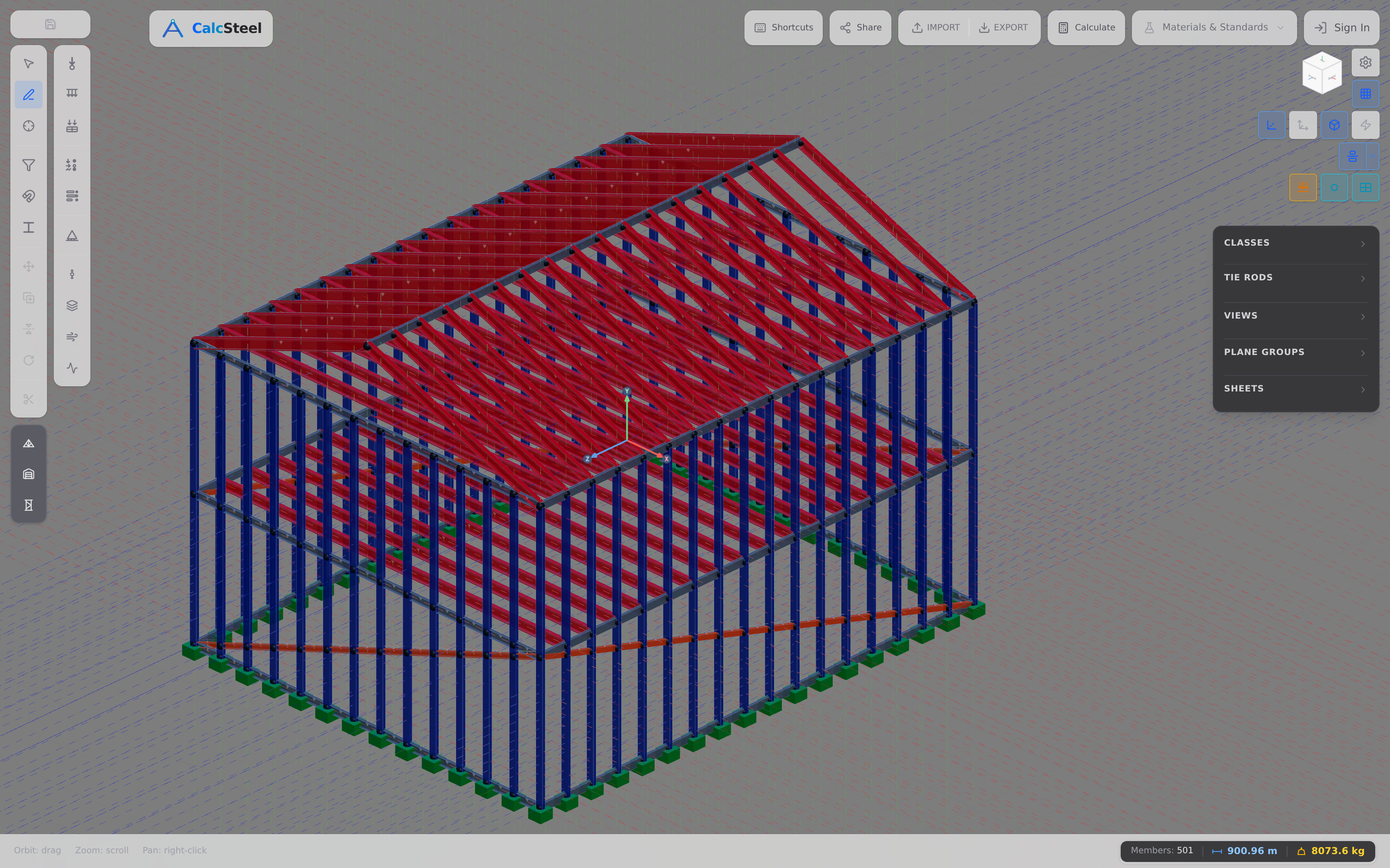
Cold-formed steel framing assembles a structure from thin steel sheet — typically 0.8 to 3 mm — roll-formed cold, without heat, into C-shaped studs and joists and U-shaped tracks, which are screwed together into wall, floor and roof panels. That is the whole idea in one sentence: no molten steel, no site welding, just precise sheet bent into stiff shapes and fastened into frames.
The members have plain-language names that are worth learning once:
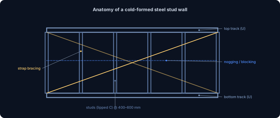
- Stud — the vertical C-section in a wall panel.
- Track — the U-section top and bottom rails the studs nest into.
- Joist — the horizontal C-section that spans a floor or flat roof.
- Nogging / blocking — short pieces between studs or joists that hold spacing and share load.
- Bridging — straps or channels that run across the frame to stop slender studs and joists from twisting.
Why the system keeps winning work:
- Strength-to-weight — a high-strength thin section carries a lot for very little mass.
- Dimensional stability — it does not shrink, warp or move with moisture the way timber does.
- Non-combustible — the steel itself does not burn.
- Termite- and rot-proof — no organic material to attack.
- Recyclable — steel is one of the most recycled materials on earth.
- Fast, dry prefabrication — panels are cut and screwed to millimetre tolerances, often off-site.
The catch — and it is the reason the design differs — is baked into that same thinness. Because the walls of the section are so slender, they buckle locally long before the steel yields. That single fact reshapes how these members are analysed and sized, and it is the thread that runs through the rest of this pillar.
The sections and the gauge
Everything in a light steel frame starts at the roll-former. Instead of squeezing red-hot billet through rollers as a hot-rolled beam is made, a coil of cold steel strip is fed through a line of shaped rollers that progressively bend it into the final profile — at room temperature. Cold-forming is what makes the thin, crisp, repeatable shapes possible; it also work-hardens the steel at the bends, raising the yield strength right where the corners are.
A handful of shapes do almost all the work:
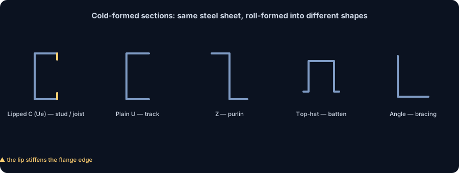
- Lipped channel (C / Ue) — the workhorse stud and joist. The little return lip at each flange edge is what makes it a good bending member.
- Plain channel (U) — the track. It has no lips so the lipped studs slide neatly inside it, top and bottom.
- Z-section and hat / top-hat — purlins and battens that carry roofing and cladding across the frame.
- Plain angle — cheap, simple bracing and connection pieces.
What the lip actually does
Look at a plain flange with a free edge: under compression that edge has nothing to hold it, so it ripples away early. Folding a small lip onto the edge stiffens it, pushes the local buckling stress up, and lets the flange carry far more before it loses effectiveness. The lip is the difference between a floppy strip and a real structural channel.
Gauge — why 0.8 to 3 mm
The steel is thin on purpose. Below roughly 0.8 mm the sheet is too flimsy to hold a screw thread reliably or resist handling damage; above about 3 mm the roll-forming lines and the self-drilling screws that define the whole system start to struggle, and you drift toward hot-rolled territory. Wall studs typically sit at the thin end; joists and headers use the thicker gauges.
To make this concrete, here is the exact section we design as a joist later in this pillar: a C 200×75×20×3.05 mm — a 200 mm web, 75 mm flanges, 20 mm lips, formed from 3.05 mm sheet. Its properties are A = 11.62 cm², Ix = 718.9 cm⁴ and Sx = 71.89 cm³. Keep those three numbers in mind; they are what turn a load into a stress and a deflection.
Anatomy of a light-steel frame
Individually the sections are slender and easy to twist. The frame is what makes them structural — and it is assembled in three layers that hand load down to each other.
Wall panels
A wall is a row of studs at 400 or 600 mm centres captured between a top track and a bottom track. On their own the studs are long and slender and want to buckle or twist sideways, so two things restrain them: noggings (blocking) fitted between the studs to hold spacing and share concentrated loads, and bridging — flat straps or small channels threaded through the stud webs — that stops the whole row rotating about its weak axis. Miss the bridging and otherwise-adequate studs will fail by twisting long before they reach their bending strength.
Floor cassettes
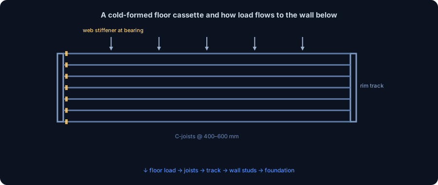
A floor is a set of C-joists at 400 or 600 mm centres landing on rim tracks at each end. Because the joist web is thin, the point where it sits on its support is a weak spot — the web can crush or fold under the concentrated reaction — so web stiffeners are added at the bearings to carry that load into the flanges. Screwed together as a unit, the joists, rim tracks and decking form a stiff cassette that can be lifted into place whole.
Roof
Above the walls sit cold-formed trusses or rafters — the same lipped channels and angles arranged to shed the roof loads down to the wall lines.
How the load flows
The path is deliberate and, in cold-formed work, entirely through screwed connections:
- Roof loads (self-weight, snow, wind uplift) collect on the trusses or rafters.
- They drop onto the wall panels below, which carry them vertically as axial load in the studs.
- The walls bear on the floor cassette, whose joists span to their supports and hand off vertical reactions.
- Those reactions travel down through the lower walls to the foundation.
Every hand-off is a screwed joint, and every member in that chain has to be checked for the demand it actually sees. That is exactly what the worked examples ahead do — one stud, one joist and one header at a time — with the elastic demand read straight from the FEM engine.
How cold-formed members are designed — and why it's different
Here is the single idea that separates cold formed steel framing from everything you learned about hot-rolled beams: the walls of a cold-formed section are so thin that the flat plate elements buckle out of their own plane before the whole cross-section can reach its yield stress. A hot-rolled beam is chunky enough that it usually yields first; a cold-formed lipped channel, made from sheet 0.8–3 mm thick, ripples first. That changes the entire method.
Because the compressed parts of the section shed load as they buckle, cold-formed design does not use the full, gross cross-section. It uses an effective section — the reduced amount of steel that is still doing structural work once the buckled zones are discounted. The thinner and wider a plate element is, the less of it stays "effective", which is exactly why the little lip on the flange edge matters so much: it props up the free edge of the flange and keeps more of it effective.
The three buckling modes you must check
Every cold-formed stud, joist or header has to be verified against three distinct instabilities, not just one:
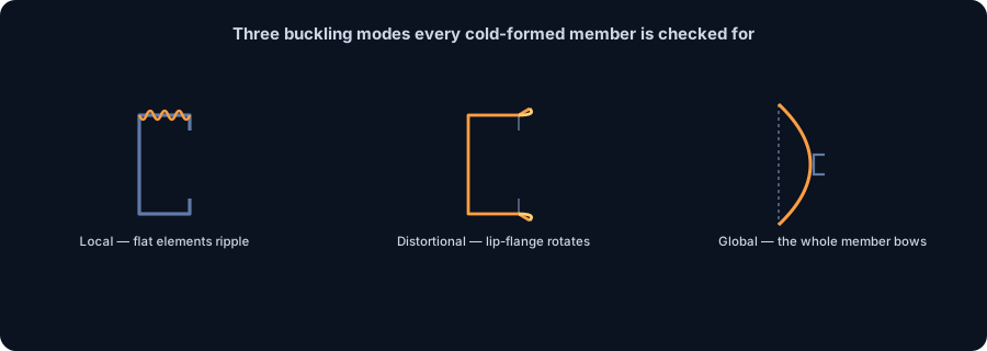
- Local buckling — the individual flat elements (web, flange, lip) ripple into short waves while the section's corners stay put. It is the first to appear and it is what forces the effective-section idea.
- Distortional buckling — the lip-and-flange assembly rotates as a unit about the web-to-flange corner, opening or closing the channel. This mode is unique to cold-formed sections and is easy to miss because it falls between the local and global wavelengths; ignoring it is one of the classic ways CFS members are over-rated.
- Global buckling — the whole member goes: flexural buckling of a stud in compression, lateral-torsional buckling of a joist in bending, or flexural-torsional buckling of the singly-symmetric channel. Bridging, blocking and sheathing exist largely to shorten the unbraced length that drives this mode.
Codes and methods
The capacity side of the calculation is codified. The dominant frameworks are AISI S100 (North America), which today is usually applied through the Direct Strength Method (DSM); Eurocode 3 Part 1-3 with its effective-width approach; NBR 14762 (Brazil); and AS/NZS 4600 (Australia/New Zealand). DSM in particular has become the modern default because it works straight from elastic buckling loads for the three modes and skips the element-by-element effective-width bookkeeping.
And there is a recurring plot twist: for cold-formed members, serviceability frequently governs before strength does. These sections are stiff for their weight in an absolute sense but they are light, so deflection under wind and — for floors — perceptible bounce and floor vibration often decide the size long before any capacity check is close to its limit. You will see this happen in the very next worked example.
Where CalcSteel fits — stated honestly
Be clear about the division of labour. CalcSteel's real FEM engine gives you the elastic demand exactly: the reactions, the shear V, the bending moment M and the deflection δ for any stud, joist or header you model, matched to closed-form theory to three decimals. What the engine does not do for you is compute the cold-formed capacity — the effective-width / DSM check for the three buckling modes above. That capacity check is the paired next step you carry out against your governing code. Getting the demand right, free and instantly, is what lets you go into that capacity check already knowing the exact M, V and δ your member has to survive.
Worked example 1: a wall stud under wind
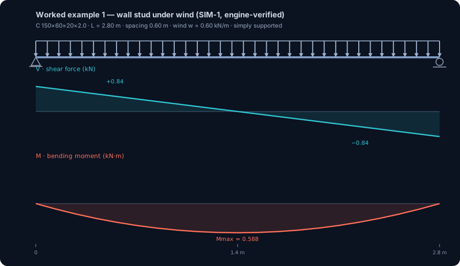
Let's turn the theory into numbers on a real member. Take a common non-loadbearing wall stud under wind: a lipped channel C 150×60×20×2.0 mm (A = 6.08 cm², Ix = 215.1 cm⁴, Sx = 28.68 cm³, about 4.77 kg/m). The wall is L = 2.80 m tall, studs are at 0.60 m centres, and the design wind pressure is q = 1.0 kN/m². The stud spans vertically between the top and bottom tracks, which we model as simple pins.
Step 1 — tributary line load
Each stud collects the wind over the strip of wall it supports — its spacing. So the pressure becomes a uniform line load along the stud:
w = q × spacing = 1.0 kN/m² × 0.60 m = 0.60 kN/m, acting horizontally (perpendicular to the wall).
Step 2 — reactions and shear
For a simply supported member under a uniform load, each track shares the total load equally. The engine returns R = 0.84 kN at each end, and the shear is largest at the supports, Vmax = ±0.84 kN, falling linearly through zero at mid-height. This is the first time we have used V and M in this pillar — if the shear-force and bending-moment diagram is not yet second nature, our companion deep-dive on shear force and bending moment diagrams walks through exactly how these shapes arise.
Step 3 — bending moment
The moment builds parabolically to a peak at mid-height. The engine reports Mmax = 0.588 kN·m, precisely the classic wL²/8 for a pinned span (0.60 × 2.80² / 8 = 0.588). This is the demand the effective section and its DSM capacity have to resist about the strong axis.
Step 4 — lateral deflection vs the serviceability limit
Under wind, a wall's comfort and finish crack-control limit is typically L/240. Here that is 2800 / 240 = 11.7 mm. The engine computes an actual mid-height deflection of δ = 1.12 mm — the stud uses only about 10% of its deflection budget. The FEM result matched the closed-form theory exactly.
What this tells you
For this non-loadbearing stud, wind bending is comfortable and stiffness is nowhere near its limit — the design is driven by the capacity checks (local and distortional buckling of that thin 2.0 mm section), not by deflection. But note the scope: this is a pure bending check. The moment a stud also carries vertical load from the storey above, it becomes a beam-column, and you must verify the combined axial-plus-bending interaction — axial compression amplifies the wind moment and drags global and distortional buckling into play together. That combined check is the next member-design step, and the exact M and V you just extracted here are half of what it needs.
Worked example 2: a floor joist where deflection governs
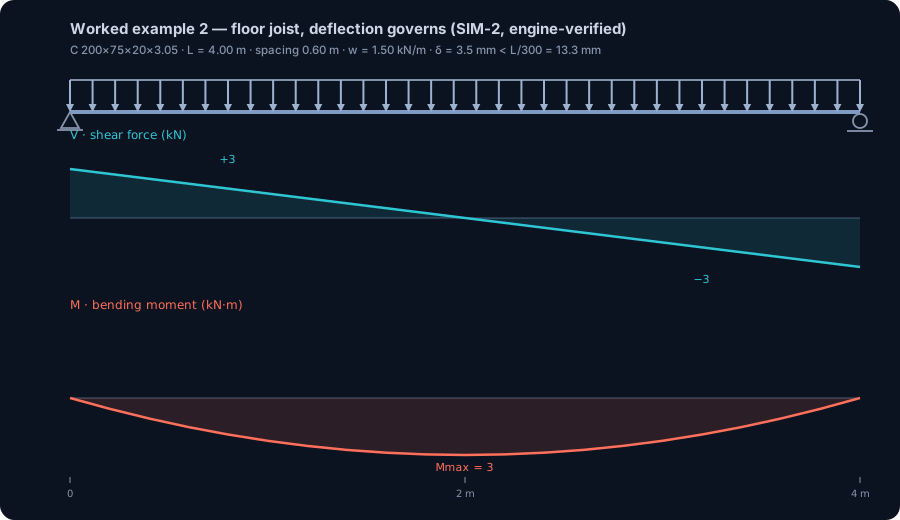
Now flip the member over and put it in a floor, where a completely different criterion takes charge. Our joist is a C 200×75×20×3.05 mm lipped channel (A = 11.62 cm², Ix = 718.9 cm⁴, Sx = 71.89 cm³, about 9.12 kg/m) — the exact section introduced earlier. It spans L = 4.00 m, joists are at 0.60 m centres, and the total floor load (dead plus live) is 2.5 kN/m². Both ends sit simply supported on the rim tracks.
Step 1 — line load
Each joist carries its tributary strip: w = 2.5 kN/m² × 0.60 m = 1.50 kN/m, this time acting vertically (gravity).
Step 2 — reactions, shear and moment
The engine returns R = 3.0 kN at each bearing and Vmax = 3.0 kN at the supports. The bending moment peaks at midspan at Mmax = 3.00 kN·m — again exactly wL²/8 (1.50 × 4.00² / 8 = 3.00). With Sx = 71.89 cm³, the elastic bending stress this produces is modest, and the section has a large strength reserve even after the effective-section reduction.
Step 3 — deflection is the real story
Floors are held to a tighter serviceability limit than walls — typically L/300 for total-load deflection, here 4000 / 300 = 13.3 mm. The engine computes an actual midspan deflection of δ = 3.48 mm, the textbook 5wL⁴/384EI with E = 200 GPa, matched by the FEM to three decimals. That is only about 26% of the deflection limit — comfortable, but a much bigger fraction of the budget than the strength check is using.
The teaching point
This is cold-formed design in a nutshell. The joist has plenty of moment capacity to spare, yet stiffness, not strength, is what actually sizes it. Push the span out, cut the depth, or thin the gauge and δ climbs toward 13.3 mm long before the bending capacity is threatened. And deflection is only half of the serviceability conversation: because CFS floors are light, floor vibration and bounce — how the floor feels when someone walks across it — often become the true controlling criterion, tightening the effective span limits further than a static deflection check alone would suggest. When you hear that cold-formed joists are "deflection-governed", this is what it means, and it is why getting δ exactly right in the browser — before you ever open the capacity code — is so valuable.
Size your own member: the live calculator
Reading a worked example is one thing; driving the numbers yourself is where cold-formed steel framing finally clicks. The interactive beam calculator mounts right here, running the same elastic FEM engine that produced every result in this guide. Set the span, drop in a line load, choose the support condition, pick a cold-formed section, and read the reactions, shear force V, bending moment M and deflection δ back instantly.
Try it with the members you have already met in this pillar. Type in a C 150×60×20×2.0 wall stud at L = 2.80 m with w = 0.60 kN/m and you will land on the same 0.588 kN·m mid-height moment and 1.12 mm deflection. Swap to the C 200×75×20×3.05 floor joist at L = 4.00 m with w = 1.50 kN/m and watch deflection climb to 3.48 mm — the number that actually governs a cold-formed floor. Then start changing things: stretch the span, tighten the stud spacing, or push the wind pressure up and see how fast a thin section eats into its deflection limit.
A few things worth knowing before you start:
- It is genuinely free. The math is unlimited and needs no login — open the beam calculator and go. CalcSteel runs entirely in your browser, so nothing is queued on a server and nothing is metered.
- The engine returns elastic demand, not capacity. You get M, V and δ to three decimals, matched against closed-form theory. The paired step — the effective-width / Direct Strength Method capacity check that turns that demand into a pass/fail — is the cold-formed code work described earlier in this guide; the calculator sizes the demand side of that comparison exactly.
- Support type changes everything. Toggle between pinned and fixed ends and you will see the peak moment jump between mid-span and the supports — the very effect we quantify in the pinned-vs-fixed example below.
Punch in your own stud, joist or header and keep it open in a second tab as you read the remaining worked examples — every claim that follows is one you can reproduce here in seconds.
Max moment
45 kN·m
Max shear
30 kN
Max deflection
10.55 mm
= L/569
Bending stress σ
84.4 MPa
σ = M/Sx
Utilization
44.0%
NBR 8800 · δ ≤ L/250
Geometry & supports
Section
Ix 7999 cm⁴ · Sx 533 cm³ · 42.2 kg/m
Point loads (↓ positive)
None — add as many as you need.
Distributed loads (uniform or trapezoidal)
Model sketch
Diagrams — free PNG / SVG / CSV export, no watermark
Step-by-step — the calculation memory of YOUR beam
IPE 300 · L = 6 m · fy = 250 MPa
1. Reactions (equilibrium of the solved FEM model)
ΣFy = 0 · ΣM = 0
R_A = 30 kN · R_B = 30 kN
2. Peak shear (read from the SFD)
Vmax = |V(x)|max
Vmax = -30 kN @ x = 6 m
3. Peak moment (read from the BMD)
Mmax = |M(x)|max
Mmax = 45 kN·m @ x = 3 m
4. Peak deflection
EI = 15998 kN·m² (E = 200 GPa)
δmax = 10.55 mm @ x = 3 m = L/569
5. Elastic bending stress
σ = Mmax / Sx = 45.00 × 10³ / 533.3
σ = 84.4 MPa
6. Bending check — both codes, side by side
NBR 8800: σ ≤ fy/1.10 = 227.3 MPa · AISC 360: σ ≤ 0.90·fy = 225 MPa
NBR 37.1% PASS · AISC 37.5% PASS
7. Deflection check (serviceability — code-independent)
δ ≤ L/250 = 24 mm
10.55 mm / 24 mm = 44.0% PASS
Recomputed live from the current inputs by the direct-stiffness FEM engine — change any load and every step updates. Reproduce it by hand with the formulas in the sections below.
Lightest catalog profiles that pass (974 flexural candidates · NBR 8800)
| Profile | Std | Weight | Total steel | σ util | δ util | |
|---|---|---|---|---|---|---|
| W310x21 | AISC | 21 kg/m | 126 kg | 83% | 98% | |
| VS 300x23 | BR | 22.6 kg/m | 136 kg | 71% | 84% | |
| U 300x90x6.3 | BR | 23.1 kg/m | 139 kg | 82% | 98% | |
| U 300x100x6.3 | BR | 24.1 kg/m | 145 kg | 77% | 91% | |
| VS 250x25 | BR | 24.6 kg/m | 148 kg | 70% | 100% |
Elastic bending (σ = M/Sx vs fy/γa1, γa1 = 1.10 — NBR 8800) + deflection screening of the full flexural catalog. Lateral-torsional buckling, shear and local buckling are NOT checked here — run the full NBR 8800 / AISC 360 verification in the 3D editor.
Worked example 3: a header over an opening
Every door and window punches a hole in the wall framing, and the studs that used to carry load through that hole now have to detour around it. That job falls to the header (or lintel): a beam over the opening that gathers the roof, floor and wall load from above and hands it down to the jamb studs flanking the opening. Headers are where cold-formed steel framing stops being a field of identical studs and starts concentrating load — so they deserve a careful look.
The demand
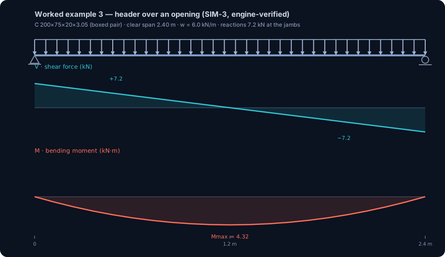
Take a header built from the same C 200×75×20×3.05 mm lipped channel we used for the floor joist, spanning a clear opening of L = 2.40 m. Above it sits a tributary strip of roof plus the wall, delivering a line load of w = 6.0 kN/m. Model it as simply supported on the two jamb studs and the engine returns:
- Reactions R = 7.2 kN at each jamb (½ · 6.0 · 2.40).
- Shear Vmax = 7.2 kN, peaking at the supports and crossing zero at mid-span.
- Bending moment Mmax = 4.32 kN·m at mid-span (= wL²/8).
- Deflection δ = 1.80 mm at mid-span.
The engine matched closed-form theory exactly. Notice the moment is comfortably higher than the wind stud's 0.588 kN·m but the span is short and stiff, so deflection stays small — here it is strength and bearing, not serviceability, that lead the conversation.
Two details that make a header a header
1. Real headers double up. A single thin C would be a poor beam over an opening — slender, prone to lateral-torsional and distortional buckling, and easy to twist. So in practice a header is built as a boxed pair: two C sections placed back-to-back (or web-to-web inside a track) and screwed into one built-up member. Two channels sharing the same demand means each C carries roughly half — the 4.32 kN·m and 7.2 kN split between them — which is exactly why you box them. When you drive this in the calculator, remember the elastic demand it reports is the total on the built-up header; the capacity check is then run per channel on the effective section.
2. The reaction lands somewhere. That 7.2 kN reaction concentrates on the jamb studs as a bearing force pressed into a thin web. Cold-formed webs are only ~3 mm here, so a concentrated support reaction can crush or buckle the web locally — the failure mode called web crippling. This is unique to thin-walled members and is easy to miss because the beam checks (moment, deflection) all pass. The fixes are standard cold-formed detailing: verify web crippling at the bearing, and where it does not pass, add a bearing stiffener (a short length of channel or angle screwed into the web at the reaction) to spread the load. The jamb studs themselves must also be sized to carry that 7.2 kN down to the floor.
The header is the clearest reminder that cold-formed design is a system: the engine gives you the exact M, V and δ, and it is up to you to follow the reaction into the jamb, check the web at the bearing, and box the section so no single thin channel is doing a job it was never shaped for.
Boundary conditions matter: pinned vs fixed
How you assume a member is held at its ends changes the answer more than almost any other single choice — and cold-formed steel framing is full of connections that are genuinely ambiguous. So let's take the exact wind stud from the first worked example and change only the boundary conditions.
Same stud, clamped ends
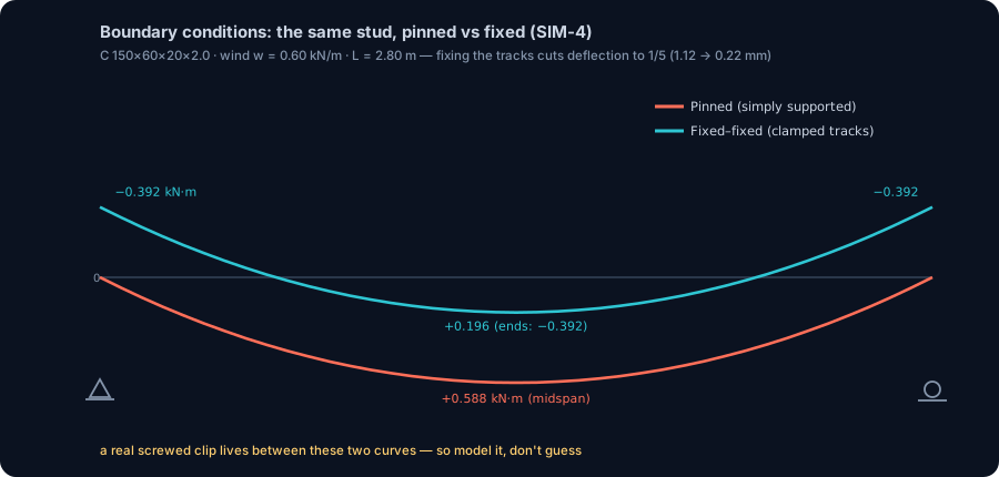
The member is unchanged: a C 150×60×20×2.0 mm stud, height L = 2.80 m, carrying the same wind line load w = 0.60 kN/m. Earlier we treated the top and bottom track connections as perfect pins. Now assume the opposite extreme — both track connections fully clamped (fixed–fixed), unable to rotate. The engine returns:
- Mend = −0.392 kN·m at each track (= wL²/12) — the peak moment has moved to the ends.
- Mmid = +0.196 kN·m at mid-height (= wL²/24).
- Deflection δ = 0.22 mm — roughly one fifth of the pinned 1.12 mm.
Compare that with the pinned run, where the peak was a single +0.588 kN·m sag at mid-height and deflection was 1.12 mm. Nothing about the steel changed. By clamping the ends we:
- Relocated the critical moment from mid-height to the supports — so the check that matters, and the place you would add reinforcement, moves too;
- Reversed its sign at the ends (hogging, not sagging), which flips which flange is in compression and therefore which buckling mode you screen for;
- Cut the deflection roughly five-fold, because end fixity is enormously stiffening.
The honest answer is in between
Here is the engineering truth: a real screwed clip at the track is neither a perfect pin nor a perfect fixity. A light clip lets the stud rotate almost freely; a stout bracket with several screws restrains it substantially. The actual behaviour — and the actual moments and deflection — sit somewhere between these two engine runs. Assume a pin and you may over-design for a mid-height moment that never fully develops; assume full fixity and you may miss the hogging moment and the concentrated demand at the track, and dangerously overstate the stiffness.
This is precisely where structural software earns its keep. Rather than guess a single boundary condition and hope, you bracket the problem: run the pinned case and the fixed case in the beam calculator, confirm your detail is safe across the whole range, and detail the connection to match whichever end of that range you are relying on. Two runs, thirty seconds, and the ambiguity that used to be a judgement call becomes a bounded, defensible number — the elastic demand at both extremes, ready for the cold-formed capacity check that follows.
Connections, and how CFS differs from hot-rolled
A cold-formed steel frame is only as good as the screws that hold it together. Because the sheet is thin, you never site-weld light gauge framing — the heat would burn through the material and destroy the zinc coating that keeps it from corroding. Instead, cold-formed connections are made cold, fast, and by the hundred:
- Self-drilling / self-tapping screws — the workhorse. The screw drills its own hole and forms its own thread in one action, joining stud to track, sheathing to stud, and clip to member. No pre-drilling, no torque wrench, just a screw gun.
- Clinching (press-joining) — a die presses the two sheets into an interlocking button with no separate fastener; common in factory-made panels and trusses.
- Blind (pop) rivets — where you can only reach one side of the joint, typical at cladding and flashings.
- Powder-actuated pins — driven fasteners that anchor the bottom track to a concrete slab in one shot.
The mental shift from hot-rolled is this: a screwed joint works as a group. No single fastener carries the connection — the load is shared across a pattern of screws, and the joint is designed by fastener count and spacing, checking each screw for shear, pull-out (tension out of the threaded sheet) and pull-over (the sheet tearing over the head), plus bearing and tilting in the thin ply. Add screws, or spread them further apart, and the capacity grows almost linearly — until the sheet itself, not the screw, becomes the limit.
How this differs from hot-rolled steel
Hot-rolled sections are thick — flanges and webs measured in whole millimetres or centimetres — so their plate elements are stocky. A hot-rolled beam generally yields before it buckles locally, it is joined by welds and high-strength bolts, and it shrugs off concentrated bearing forces. Cold-formed members are the mirror image: thin walls that buckle locally and distortionally long before the steel yields, joined by screws working in groups, and sensitive to any point load pressing on an unstiffened web. Neither is "better" — they solve different problems, and a good building often uses hot-rolled for the primary skeleton and cold-formed for the infill walls, floors and roof.
For the full section-by-section, metallurgy-and-shape comparison — how the material is made, which yields first, and when to reach for each — read the companion piece: hot-rolled vs cold-formed steel.
Common mistakes & FAQ
Cold-formed steel framing rewards discipline. The same slenderness that makes it light and efficient also makes it unforgiving of the shortcuts you might get away with in hot-rolled or timber. Here are the six that catch people out most often:
- Ignoring distortional buckling. Everyone remembers to check local and global buckling; distortional — where the lip and flange rotate as a unit about the web-flange corner — is unique to cold-formed sections and often governs the capacity of a stud or joist. Never leave it out of the capacity check.
- Forgetting web crippling and bearing stiffeners. A thin web carrying a concentrated reaction will simply fold. Wherever a joist lands on a track, or a header reaction lands on the jamb studs, check web crippling and add a web/bearing stiffener if the number doesn't pass. Our header example concentrated 7.2 kN at each jamb for exactly this reason.
- Sizing for strength when deflection and vibration govern. Because these members are stiff-for-weight but not stiff-in-absolute-terms, floors and wind-loaded walls are usually limited by L/300 or L/240 and by floor bounce — not by yielding. Our floor joist used only ~26% of its deflection limit and had a huge strength reserve, yet deflection was still the story.
- Assuming full end fixity. A screwed clip is neither a perfect pin nor a perfect fixity. Design the real detail for the demand that the true, partial restraint produces — bracket it between the pinned and fixed models rather than optimistically claiming a fixity you didn't detail.
- Skipping bridging and blocking. Slender studs and joists want to twist and buckle sideways. Strap or channel bridging, noggings and blocking brace them at intervals — leave them out and the member's real capacity collapses well below the calculated value.
- Neglecting corrosion and thermal bridging. Specify the galvanising/coating class for the exposure (thin steel has little sacrificial metal to spare), keep the steel dry, and detail thermal breaks so the highly-conductive studs don't cold-bridge the envelope and drive condensation.
Frequently asked questions
Is cold-formed steel framing strong enough for a house? Comfortably. Cold-formed framing routinely builds single- and multi-storey houses and mid-rise buildings; its strength-to-weight ratio is excellent. The design task is not raw strength but controlling buckling and deflection — which is precisely what the effective-section capacity checks and the serviceability limits are for.
How far can a cold-formed steel joist span? It depends entirely on the section, gauge, spacing and load — there is no single number. In our worked example a C 200×75×20×3.05 mm joist at 0.60 m spacing spanned 4.00 m under a 2.5 kN/m² floor load and used only about a quarter of its L/300 deflection limit, so a deeper section or thicker gauge would reach further. The honest answer is: model your exact member and read the deflection.
What gauge steel is used for wall studs? Typically thin — non-loadbearing partition studs are often around 0.8–1.2 mm, while structural loadbearing studs and joists run heavier, commonly up to about 2–3 mm. Our wind stud was a 2.0 mm C-section; our loadbearing joists and headers were 3.05 mm.
Cold-formed vs hot-rolled — which is cheaper? For light and repetitive structures (housing, low-rise, infill walls and floors) cold-formed usually wins on installed cost: less steel by weight, no site welding, fast dry prefabrication and lighter foundations. For heavy, long-span or high-load primary structure, hot-rolled is generally more economical. Most projects mix the two — see the hot-rolled vs cold-formed comparison for where the crossover sits.
Key takeaways
From a single stud to a full wall-and-floor, here is what cold-formed steel framing comes down to:
- Cold-formed steel framing builds real buildings from thin steel sheet (≈0.8–3 mm) roll-formed cold into C-studs, C-joists and U-tracks, screwed into wall, floor and roof panels — light, dimensionally perfect, non-combustible and fast to erect.
- Thinness changes the physics. These members buckle locally, distortionally and globally long before they yield, so design uses an effective section (effective-width / Direct Strength Method under AISI S100, Eurocode 3-1-3, NBR 14762 or AS/NZS 4600) — never the gross section.
- Serviceability usually governs. Across our worked examples the members had large strength reserves; deflection (L/300 for floors, L/240 for wind-loaded walls) and floor vibration are what actually size cold-formed studs, joists and headers.
- Details decide capacity. Web crippling and bearing stiffeners at supports, bridging and blocking against twist, and realistic end restraint (a screwed clip lives between a pin and a fixity) are not optional extras — they are the design.
- CalcSteel gives you the exact elastic demand for free. The real FEM engine returns reactions, shear, moment and deflection for any stud, joist or header — every number in this article matched closed-form theory to three decimals — and the effective-width / DSM capacity check is the paired next step.
Ready to try it on your own member? Drive the free beam calculator right now — set your span, load, supports and a cold-formed section and read V, M and deflection instantly, unlimited and with no login for the math. When you want the full 3D frame, the genuinely-free CalcSteel plan runs entirely in your browser with the real FEM engine behind it. And if you're a student or a university lab, the CalcSteel /education offer is free — so you can learn cold-formed design on the same engine practising engineers use.
Sources
Try CalcSteel for free
Model, analyze and design steel structures in your browser. No install, no signup.
Open the 3D editor