Steel Cross Bracing: the Effective-Length Criterion Behind the Code
Steel cross bracing looks like the simplest lateral system there is: two diagonals in an X, one in tension and one in compression, carrying the story shear straight down to the foundation. The whole design turns on one number the drawings never show, the effective length of the compression diagonal. Take it as the full diagonal and a perfectly good tube fails; recognise that the tension diagonal braces the crossing point and the same tube passes with room to spare. This guide derives that criterion from first principles, then runs the real CalcSteel engine on a 6.0 m by 4.0 m bay to size the diagonals and prove the check.
Key takeaways
- Steel cross bracing carries a story shear as a tension / compression pair of diagonals. For a symmetric X the two diagonals share it equally, each takes H divided by two cosine theta; design it tension-only and the tension diagonal takes the full H over cosine theta.
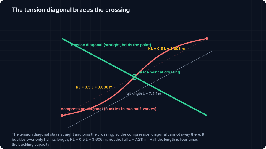
- The criterion behind the code is the effective length of the compression diagonal. In an X the taut tension diagonal restrains the crossing point, so the compression diagonal buckles over HALF its length: KL = 0.5 L, not the full 7.211 m.
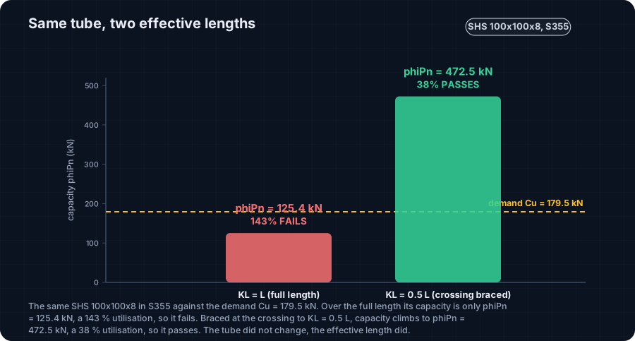
- Worked check, one SHS 100x100x8 tube, S355: assume the full length and phi Pn = 125.4 kN against Cu = 179.5 kN, a 143% check that FAILS. Take KL = 0.5 L and phi Pn = 472.5 kN, a 38% check that PASSES. Same tube, same load, different length.
- The engine confirms the demand: on the 6.0 m by 4.0 m bay the two diagonals carry 179.5 kN and −179.5 kN, within 0.4% of the pin-truss value 180.3 kN. Tension almost never governs, phi Pn = 940.6 kN, 19% utilised; the compression diagonal is what sizes the brace.
- Keep the compression slenderness KL/r at or below 200 and the tension diagonal at or below 300, connect the two diagonals at the crossing so the brace point is real, and design the beams, columns and connections for the brace capacity, not the elastic demand.
What steel cross bracing really is
Steel cross bracing, an X of two diagonals across a bay, is the stiffest and cheapest way to stop a steel frame from swaying. Wind or an earthquake pushes the floor sideways; the X turns that horizontal push into pure axial force in the diagonals and sends it straight to the base. No bending, no drift, just two struts and ties working in line. It is why nearly every warehouse, tower core and mezzanine you have ever seen hides an X somewhere in its walls.
Because the load path is so simple, the design looks simple too, and that is the trap. When the frame leans one way, one diagonal stretches (tension) and the other shortens (compression). The tension diagonal is almost never the problem: steel is enormously strong in tension. The compression diagonal is the whole game, because a long, thin diagonal does not crush, it buckles, and buckling strength collapses with the square of the length.
So the entire check comes down to one length: how far can the compression diagonal buckle over? Get that wrong and you either fail a tube that is actually fine, or, worse, pass one that is not. This article derives the answer from statics, then runs a full worked check on a real section with forces computed by the CalcSteel FEM engine on a 6.0 m by 4.0 m bay. You can reproduce the buckling capacity yourself in the calculator embedded further down.
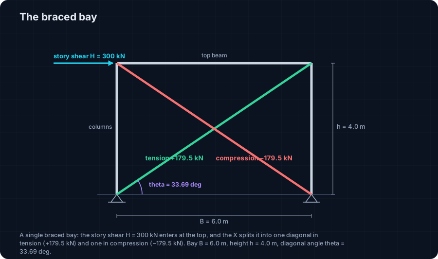
X-brace vs single diagonal vs chevron
Here is a definition you can quote: steel cross bracing is a lateral system in which two diagonal members cross a bay in an X, so that under a horizontal load one diagonal works in tension and the other in compression, carrying the story shear to the foundation as axial force.
Why the X, and not one diagonal? A single diagonal has to work both ways: it is a tie when the frame leans one direction and a strut when it leans the other, so it must be sized for compression over its full length, the least efficient case. A chevron (inverted V) puts two diagonals below a beam, but forces an unbalanced vertical load into that beam when one diagonal buckles, which is why chevron beams get heavy. The X is the sweet spot: the two diagonals cross and can be connected where they meet, and that connection is exactly what shortens the buckling length of whichever diagonal is in compression. The geometry that looks like a detailing convenience is doing structural work.
New to lateral systems in steel? Our overview of bracing systems for steel structures sets the scene, and what a brace must actually deliver covers the stiffness side. Here we go straight to the number that sizes the cross brace.
The load path: where the tension and compression come from
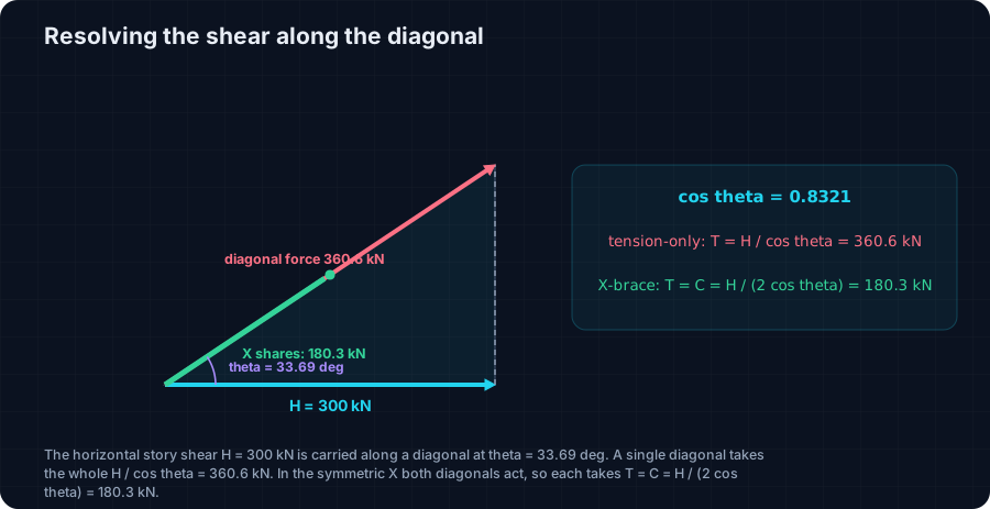
Start with statics. A story shear H reaches the bay through the floor diaphragm and has to be resisted by the horizontal components of the diagonal forces. Each diagonal sits at an angle theta to the horizontal, with cosine theta = B / L = 6.0 / 7.211 = 0.8321 for our bay. Resolve the horizontal equilibrium at the top of the bay:
(T + C) · cos θ = H
For a symmetric X the two diagonals are identical mirror images, so under a symmetric story shear they take equal and opposite force, T = C. That splits the shear in half:
T = C = H / (2 cos θ) = 300 / (2 · 0.8321) = 180.3 kN
That is the tension / compression design, where you count on both diagonals working at once. There is a second, very common way to design a cross brace: tension-only. You assume the compression diagonal has already buckled and sheds its load, so the tension diagonal alone carries the whole story shear:
T = H / cos θ = 300 / 0.8321 = 360.6 kN
Tension-only is the standard choice for slender braces such as rods and flats, which cannot carry meaningful compression anyway. Tension / compression is used when the diagonals are stocky enough to work both ways, which is where the effective-length criterion earns its keep. We will check the compression diagonal, the harder case, and the engine section below confirms both numbers.
The criterion behind the code, from first principles
Now the number that matters. The compression diagonal is a strut, and a strut's capacity is governed by buckling. Euler's result is the whole story: the load at which a pinned strut buckles is
Pcr = π² E I / (KL)²
Everything hinges on KL, the effective length, the distance over which the member is free to bow out. Halve KL and you quadruple the buckling load. So the question is not how strong the tube is, it is how long a piece of it is free to buckle.
Here is the criterion. In an X-brace the two diagonals cross and, if you connect them where they meet, the tension diagonal, pulled taut, holds that crossing point still. For the compression diagonal the crossing is therefore a brace point: it cannot buckle across the full diagonal, only over the half between its end and the crossing. This is the basis Picard and Beaulieu put on a firm footing: for an X-brace with the diagonals interconnected at the intersection and one carrying tension, design the compression diagonal for an effective length of
KL = 0.5 L = 0.5 · 7.211 = 3.606 m
an effective length factor K of about 0.5 on the full diagonal length. El-Tayem and Goel confirmed the half-diagonal basis experimentally, measuring closer to 0.85 of the half length for single angles. One caveat matters: the restraint is only as real as the tension diagonal that provides it. It grows with the tension force and the tension diagonal's stiffness, so the crossing connection is not optional, and a lightly loaded or slack tension diagonal lets the brace point soften and pushes K back toward 1.0. Take the full length and you are designing as if the crossing were not there. The rest of this article shows exactly what that costs.
The capacities you need: buckling, yield and slenderness
The check needs three things from the section, and the code writes each one down.
1. Compression buckling (AISC 360 E3). The elastic (Euler) stress is Fe = π² E / (KL/r)², where r is the radius of gyration. The code then reduces it for real, imperfect members. Below the slenderness limit 4.71√(E/Fy) = 111.8 the failure is inelastic and Fcr = 0.658(Fy/Fe) Fy; above it the member is fully elastic and Fcr = 0.877 Fe. The design compression is φPn = 0.90 Fcr Ag. This is exactly the E3 curve the criterion above feeds, through KL/r.
2. Tension yield (AISC 360 D2). The tension diagonal is checked for yielding on the gross section, φPn = 0.90 Fy Ag (and rupture on the net section at the connection, which we note but do not size here).
3. Slenderness limits. AISC 360 recommends KL/r ≤ 200 for compression members and L/r ≤ 300 for tension members. These are not strength equations, they are housekeeping: a member past those ratios is too floppy to handle, ship and erect straight, and sags under its own weight. For seismic braced frames AISC 341 is stricter still, capping the brace slenderness so the brace behaves predictably through load reversals.
Two capacities, one geometric fact (KL = 0.5 L). Next we put numbers to them.
Worked check, part 1: the demand from the engine
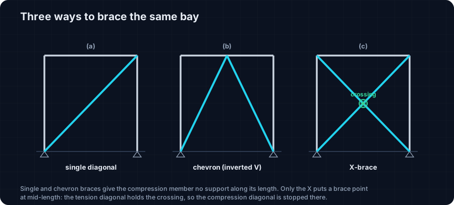
We built the exact bay from the top of this article in the CalcSteel FEM engine: a single-story X-braced bay, 6.0 m wide and 4.0 m tall, with the story shear H = 300 kN delivered through the top of the bay as a floor diaphragm would. The engine solves the indeterminate frame and returns the axial force in every member.
The two diagonals come back as:
- Tension diagonal: T = +179.5 kN.
- Compression diagonal: C = −179.5 kN.
Two checks on that result. First, symmetry: the engine gives |T| = |C| = 179.5 kN exactly, as a symmetric X must. Second, the hand value: T = C = H / (2 cos θ) = 180.3 kN, and the engine sits within 0.4% of it, at 179.5 kN. The small remainder is genuine frame action, the columns take a sliver of the shear in bending, which is real and on the safe side for the diagonal. The pin-truss formula is not an approximation you hope holds; it is what the frame actually does.
Remove one diagonal in the same model and the survivor jumps to 357.7 kN, confirming the tension-only value H / cos θ = 360.6 kN. So the factored demand on the compression diagonal is Cu = 179.5 kN. Now we size for it.
Worked check, part 2: the criterion, in numbers
The section
Take a SHS 100x100x8 square tube in S355 steel (Fy = 355 MPa, E = 200000 MPa). Its properties: Ag = 2944 mm², I = 418.4 cm⁴, r = 37.7 mm. The full diagonal length is L = 7.211 m.
The wrong way: full length
Assume the diagonal buckles over its full length, KL = 7.211 m. Then KL/r = 191.3, well above the 111.8 limit, so it is elastic: Fe = 54.0 MPa, Fcr = 0.877 · 54.0 = 47.3 MPa, and φPn = 0.90 · 47.3 · 2944 = 125.4 kN. Against Cu = 179.5 kN that is a 143% check: it fails, and comfortably. On this basis you would throw the tube away and reach for a much heavier section.
The right way: half length
Now use the criterion. The tension diagonal braces the crossing, so KL = 0.5 L = 3.606 m and KL/r = 95.6. That is below the 111.8 limit, so the failure is inelastic: Fe = 215.8 MPa, Fcr = 0.658(355/215.8) · 355 = 178.3 MPa, and φPn = 0.90 · 178.3 · 2944 = 472.5 kN. Against Cu = 179.5 kN that is a 38% check: it passes, with margin.
Same tube, same 179.5 kN, same steel. The only thing that changed is whether you credited the crossing as a brace point. That single decision moved φPn from 125.4 kN to 472.5 kN, a factor of 3.8, because capacity scales with 1/(KL)². That is the criterion behind the code, in one worked line.
See it yourself: the live buckling calculator
The whole criterion is one input: the effective length. In the calculator below, enter the SHS 100x100x8 tube in S355 and set the length to the full 7.211 m, then watch the capacity, and drop it to 3.606 m to see it jump. You are watching φPn move from failing to passing purely because the buckling length halved. That is a cross brace in miniature.
It is the same AISC E3 engine used for the worked numbers above, free, and with no login for the math.
End conditions (buckling case)
Pinned – Pinned
Cross-section
Slenderness KL/r
134.7
limit 200 · OK
Euler Pcr (elastic)
310.7 kN
Fe = 108.9 MPa
AISC 360 φcPn
245.2 kN
Fcr = 95.5 MPa · elastic
NBR 8800 Nc,Rd
247.7 kN
χ = 0.382 · λ₀ = 1.52
Code vs code — same column
Nc,Rd / φcPn = 1.010
Both codes share the 0.658 / 0.877 buckling curve — the ~1% gap is purely φc = 0.90 (AISC) vs 1/γa1 = 0.909 (NBR).
Demand check — Nd = 150 kN
Step-by-step derivation — live for YOUR column
IPE 200 · L = 3 m · K = 1 · fy = 250 MPa
- 1
Slenderness ratio
λ = K·L/r = 1 × 3000 / 22.28 mm
λ = 134.7 (≤ 200 ✓)
- 2
Euler elastic buckling stress and load
Fe = π²E/λ² = π² × 200,000 / 134.7² · Pcr = Fe·A = Fe × 2854 mm²
Fe = 108.9 MPa · Pcr = 310.7 kN
- 3
Buckling regime (AISC E3)
4.71·√(E/fy) = 4.71·√(200,000/250) = 133.2 < λ = 134.7
elastic buckling → use E3-3 (0.877·Fe)
Elastic range: capacity no longer depends on fy — only geometry (r, K, L) helps.
- 4
AISC 360 critical stress and design capacity
Fcr = 0.877 · Fe = 0.877 × 108.9 = 95.5 MPa · φcPn = 0.9 × Fcr × A
Pn = 272.5 kN · φcPn = 245.2 kN
- 5
NBR 8800 reduction factor and design capacity
λ₀ = √(fy/Fe) = 1.515 > 1.5 → χ = 0.877/λ₀² = 0.382 · Nc,Rd = χ·A·fy/1.1
Nc,Rk = 272.5 kN · Nc,Rd = 247.7 kN
Same 0.658/0.877 curve as AISC — the ~1% difference is φc = 0.90 vs 1/γa1 = 0.909.
Sections that work — 3 lightest of 612 catalog profiles carrying Nd = 150 kN at L = 3 m, K = 1
| Section | kg/m | φcPn (kN) | Nc,Rd (kN) | Util. | |
|---|---|---|---|---|---|
| lightestSHS 80x4 | 9.2 | 164 | 166 | 91% | |
| HSS 76x76x4.8 | 9.9 | 165 | 167 | 91% | |
| CHS 88.9x5 | 10.3 | 172 | 174 | 87% |
Pass criterion: φcPn ≥ Nd (AISC 360 LRFD) AND Nc,Rd ≥ Nd (NBR 8800) AND KL/r ≤ 200, using each section's tabulated-mass area and minimum radius of gyration.
Buckling curve — IPE 200, fy = 250 MPa
Capacity of IPE 200 by unbraced length — K = 1, fy = 250 MPa
| L (m) | KL/r | Pcr Euler (kN) | φcPn AISC (kN) | Nc,Rd NBR (kN) | Regime |
|---|---|---|---|---|---|
| 1 | 45 | 2,796 | 577 | 583 | inelastic |
| 2 | 90 | 699 | 419 | 423 | inelastic |
| 3◀ yours | 135 | 311 | 245 | 248 | elastic |
| 4 | 180 | 175 | 138 | 139 | elastic |
| 5 | 224 ⚠ | 112 | 88 | 89 | elastic |
| 6 | 269 ⚠ | 78 | 61 | 62 | elastic |
| 7 | 314 ⚠ | 57 | 45 | 45 | elastic |
| 8 | 359 ⚠ | 44 | 34 | 35 | elastic |
| 9 | 404 ⚠ | 35 | 27 | 28 | elastic |
| 10 | 449 ⚠ | 28 | 22 | 22 | elastic |
Worked check, part 3: tension, and which governs
For completeness, check the tension diagonal. Yielding on the gross section gives φPn = 0.90 · Fy · Ag = 0.90 · 355 · 2944 = 940.6 kN. Against T = 179.5 kN that is only 19% utilised. Its slenderness is L/r = 191.3, comfortably under the 300 tension limit.
That lopsided result, 19% in tension against a compression check that only just passes at half length, is the whole point of the article. Compression governs a cross brace, always. The tension diagonal is almost never the binding constraint; the section is set by how the compression diagonal buckles, which is set by its effective length, which is set by the crossing detail. Design the brace as if it were a tension member and you will size it far too light.
This is also why tension-only systems exist and are honest engineering: if the diagonal is too slender to carry useful compression (a rod or flat with KL/r well past 200), stop pretending it can. Design each diagonal for the full H / cos θ = 360.6 kN in tension, accept that the compression one buckles harmlessly, and detail the connections to take the reversal. What you must never do is take credit for compression capacity you did not check.
Detailing: making the brace point real
The criterion is only true if the structure matches the assumption. A few things have to be right, and they are where cross braces actually go wrong.
- Connect the diagonals at the crossing. The half length is bought by the tension diagonal holding the crossing point. If the two diagonals simply pass each other with no connection, there is no brace point out of plane and KL reverts toward the full length. A bolt or a small gusset at the intersection is what makes KL = 0.5 L legitimate.
- In-plane vs out-of-plane. The crossing restrains the compression diagonal out of the plane of the frame directly. In the plane of the frame it works too when the diagonals are interconnected there, but if in doubt, check both axes and let the larger KL/r govern. For a square tube the radius of gyration is equal both ways, so the worse case is simply the longer effective length.
- Watch the slenderness ceilings. AISC 360 recommends the compression KL/r stay at or below 200 and the tension L/r at or below 300. Our diagonal is at KL/r = 95.6 on the braced (half) length, well inside 200. In a seismic special concentrically braced frame that same 200 becomes a binding limit under AISC 341, not just a recommendation.
- Capacity design the rest. The beams, columns, gussets and anchor bolts that the brace frames into must be sized for the brace's capacity, not the elastic demand from the load case. In a seismic braced frame (AISC 341 SCBF) that means the expected brace tension RyFyAg and the post-buckling compression, so the brace is the fuse and everything around it stays elastic.
Codes: this check follows AISC 360-16 (E3 for compression, D2 for tension) with the X-brace effective length from Picard and Beaulieu, confirmed experimentally by El-Tayem and Goel; Eurocode 3 (EN 1993-1-1) gives the same buckling curves with its own notation, and EN 1998-1 covers the seismic detailing. In Brazil member design follows NBR 8800. The load may come from wind or earthquake, but the criterion for the compression diagonal is identical wherever it comes from.
Common mistakes & FAQ
The mistakes that most often turn a textbook-correct cross brace into a wrong check:
- Buckling the compression diagonal over its full length. If the diagonals are connected at the crossing, use KL = 0.5 L. Forgetting it, as our worked check shows, can fail a tube that is actually fine by a wide margin.
- Claiming the half length with no crossing connection. The opposite error. No connection, no brace point, no half length. The detail has to exist.
- Sizing the brace for tension. Compression governs a cross brace. Check the compression diagonal first; the tension diagonal will almost always have room.
- Mixing up tension-only and tension / compression. In tension-only each diagonal carries the full H / cos θ; in tension / compression each carries half. Use the wrong one and you are out by a factor of two.
- Ignoring the slenderness ceilings. KL/r past 200 in compression, or L/r past 300 in tension, is not just inefficient, it is a member you cannot erect straight.
FAQ
Is cross bracing tension-only or does the compression diagonal count? Both are valid. Slender braces (rods, flats) are designed tension-only; stocky braces (angles, tubes) can be designed tension / compression, and then the effective-length criterion sets the section.
Why is the effective length half the diagonal? Because the tension diagonal, connected at the crossing, holds the midpoint of the compression diagonal, so it can only buckle over half its length. K is about 0.5 on the full length.
Does cross bracing work for seismic? Yes. A special concentrically braced frame (SCBF) uses exactly this X, with AISC 341 detailing so the brace yields and buckles predictably while the rest of the frame stays elastic.
Key takeaways
Steel cross bracing is one idea done carefully: turn a story shear into axial force in two diagonals, and size the section by how the compression one buckles.
- The story shear splits as T = C = H / (2 cos θ) = 180.3 kN in a symmetric X, or the tension diagonal carries the full H / cos θ = 360.6 kN tension-only.
- The criterion is the effective length of the compression diagonal: the tension diagonal braces the crossing, so KL = 0.5 L = 3.606 m, not the full 7.211 m.
- Our SHS 100x100x8 S355 diagonal: at full length φPn = 125.4 kN fails (143%); at half length φPn = 472.5 kN passes (38%), against Cu = 179.5 kN from the CalcSteel engine. Tension is a non-event at 19%.
- Connect the diagonals at the crossing, keep KL/r at or below 200 and L/r at or below 300, and capacity-design everything the brace frames into.
Want to try the numbers on your own section? The column buckling calculator and the full CalcSteel editor are free to use, and CalcSteel is free for students. Enter your diagonal, set the effective length to half the crossing-to-crossing distance, and read φPn yourself.
Sources
- 1.AISC 360-16, Specification for Structural Steel Buildings (E3 compression, D2 tension)
- 2.El-Tayem & Goel, Effective Length Factor for the Design of X-bracing Systems (AISC Engineering Journal, 1986)
- 3.Picard & Beaulieu, on the effective length of cross-bracing (CISC Engineers' Corner, out-of-plane buckling)
- 4.AISC 341-16, Seismic Provisions for Structural Steel Buildings (F2, special concentrically braced frames)
- 5.Eurocode 3 (EN 1993-1-1) buckling and Eurocode 8 (EN 1998-1) seismic bracing
- 6.ABNT NBR 8800, Projeto de estruturas de aço e de estruturas mistas de aço e concreto
Try CalcSteel for free
Model, analyze and design steel structures in your browser. No install, no signup.
Open the 3D editor