Cables and the Catenary: Sag, Tension, and the Geometry That Carries the Load
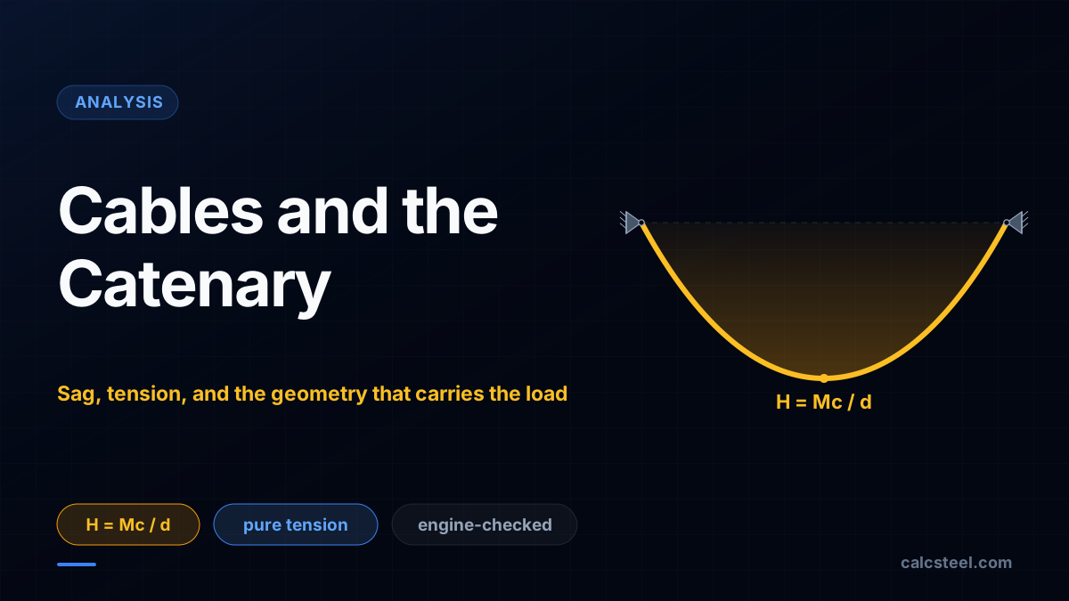
A cable cannot push, bend, or resist a moment. It can only pull. That single limitation is also its superpower: a cable has no choice but to take the exact funicular shape of whatever load it carries, so its geometry and its forces are the same fact seen twice. This guide works the pull by hand on a 20 m cable, derives the parabola and the catenary, and checks every tension against the CalcSteel FEM engine.
Key takeaways
- A cable is perfectly flexible: it carries load in pure tension, cannot take bending or compression, and therefore takes the funicular shape of its load automatically. Point loads give a polygon, a uniform load per horizontal length gives a parabola, and self-weight gives a catenary.
- The horizontal pull is H = Mc / d, the very formula the arch uses for its thrust, where Mc is the simple-beam moment at the low point and d is the sag. On a 20 m cable with a 40 kN load at midspan and 5 m of sag, H = 40 kN, matched exactly by the engine.
- Sag sets tension: H = wL2 / (8d), so halving the sag doubles the pull. A parabolic cable carrying 10 kN/m over 20 m pulls with 250 kN at 2 m of sag, 500 kN at 1 m, and would need infinite tension at zero sag.
- Tension is not constant along a cable. The horizontal component H is constant, but the total tension is least at the low point (equal to H) and greatest at the anchors. The parabolic cable above runs from 250 kN at midspan to 269 kN at the towers.
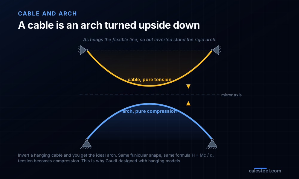
- A cable is an arch turned upside down. Invert a hanging catenary and you get the ideal compression arch, the same funicular shape and the same H = Mc / d, which is why the pull never vanishes and must always land in an anchor or a tie.
The purest structure there is
Most structural members are a compromise. A beam carries a bit of everything: bending, shear, sometimes axial. A column mostly compresses but must also be checked for the bending that buckling brings. A cable makes no compromise at all, because it is physically incapable of one. It cannot push, so it carries no compression. It has no depth to speak of, so it carries no bending and no shear. A cable can do exactly one thing: pull. Every particle of it is in pure axial tension, and nothing else.
That sounds like a crippling limitation, and in one sense it is. But it is also what makes the cable the most honest and the most tractable structure in the whole of Analise Estrutural and Estruturas I. Because a cable cannot resist bending, it cannot fight the load into a shape of its own choosing the way a stiff beam does. It has no choice but to hang in the one shape that carries the load by tension alone. That shape has a name, the funicular, from the Latin for rope, and the entire subject of this article is that the cable's geometry and its internal forces are the same fact seen twice.
This article works the whole thing end to end. One formula, H = Mc / d, does the heavy lifting, and it is the exact formula the arch uses for its thrust, which is no accident. Three worked examples put real numbers on it, each checked against the CalcSteel finite element engine: a point load that makes a V, a uniform load that makes a parabola, and self-weight that makes a catenary. Baseline geometry throughout: a span of L = 20 m between two anchors at the same level.
What a cable is, and the price of it: the anchors
A cable is a member so slender that its bending stiffness is negligible: a wire rope, a bridge strand, a chain, a prestressing tendon, a guy. Model it as perfectly flexible and the consequences are absolute. It carries no bending moment anywhere, because it has no stiffness to resist rotation. It carries no compression, because the moment you try to push on a rope it simply goes slack and buckles out of the way. What is left is the one internal force a flexible line can transmit along itself: axial tension. At every point the tension acts along the tangent to the cable, which is why the cable curves to follow the load rather than resisting it in place.
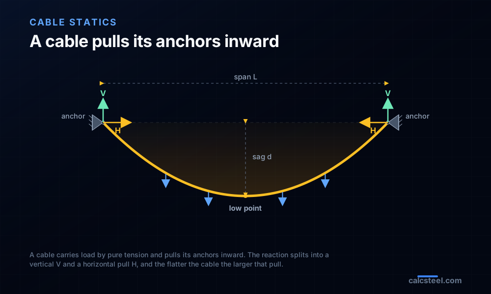
An arch pays for its compression at the supports: it presses outward, and the springings must resist being pushed apart. A cable pays the mirror-image price. Because its tension is pulling along an inclined line at each end, a loaded cable does not hang straight down from its supports. It pulls its anchors inward and down. The vertical part of that pull is V, familiar from any beam reaction. The horizontal part is the pull H, and it is the defining feature of cable behaviour: the anchors must physically resist being dragged toward each other.
Name the geometry, because the rest of the article uses it. The horizontal distance between supports is the span L. The vertical drop from the chord (the straight line between the anchors) down to the lowest point is the sag d. The supports are the anchors; the bottom of the curve is the low point. The ratio d/L is what sets the pull, and it works exactly opposite to intuition: a flatter cable (smaller sag) needs a larger H to carry the same load. Pull a clothesline tight and it still droops, because a perfectly straight cable cannot carry a transverse load at all.
The cable takes the shape of its load
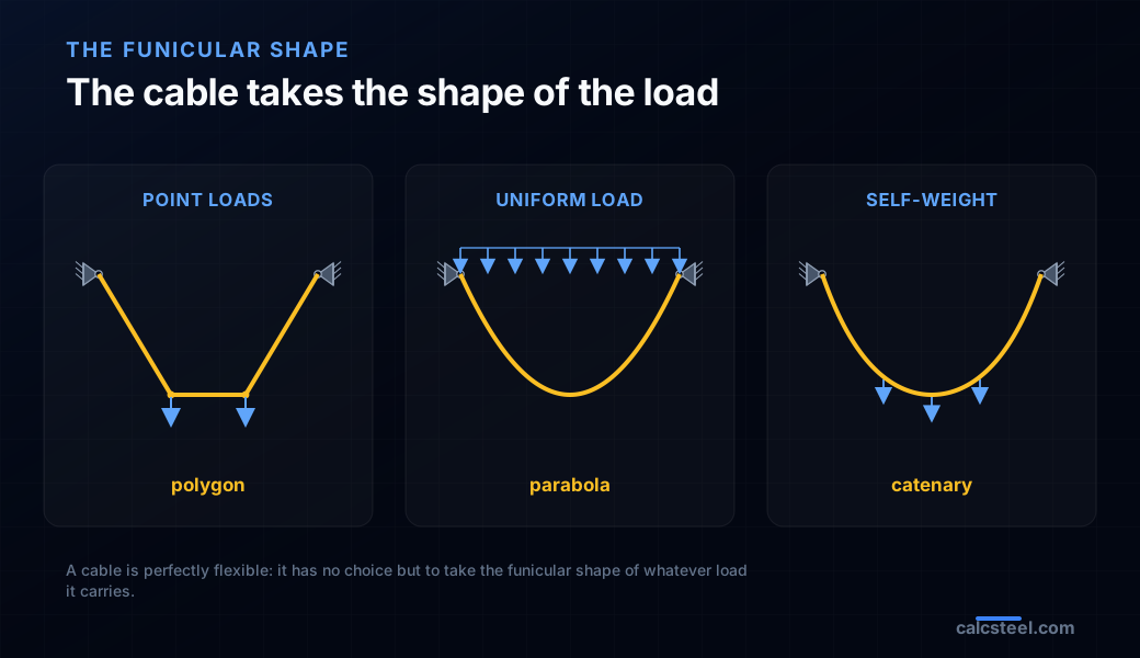
Here is the idea that unlocks everything else. Because a cable can only pull along its own length, it is in equilibrium only when its shape lines up perfectly with the load path. If any bit of the cable were the wrong shape, there would be a component of load it could not balance with pure tension, and it would move until the shape was right. So the cable finds, on its own, the funicular shape: the one curve along which the given load is carried by tension alone. You do not impose the shape on the cable. The load does.
Change the load and you change the shape, and there are three cases every course covers. Hang a few concentrated loads from the cable and it forms a funicular polygon: straight segments between the loads, with a kink at each load point, because a straight length of cable between two point loads has nothing pulling it into a curve. Apply a load that is uniform per unit of horizontal length, the way a suspension bridge deck hangs from its main cable through closely spaced hangers, and the cable takes a parabola. Let the cable carry only its own weight, which is uniform per unit length measured along the cable, and it takes a catenary, the curve of the hanging chain.
These are not approximations of one true shape. They are three exact answers to three different questions, and telling them apart is half of what this topic teaches. The parabola and the catenary in particular look almost identical when the cable is shallow and diverge when it hangs deep, and knowing when the difference matters is a real engineering judgment we settle with numbers later in the article.
The method: H equals the simple-beam moment over the sag
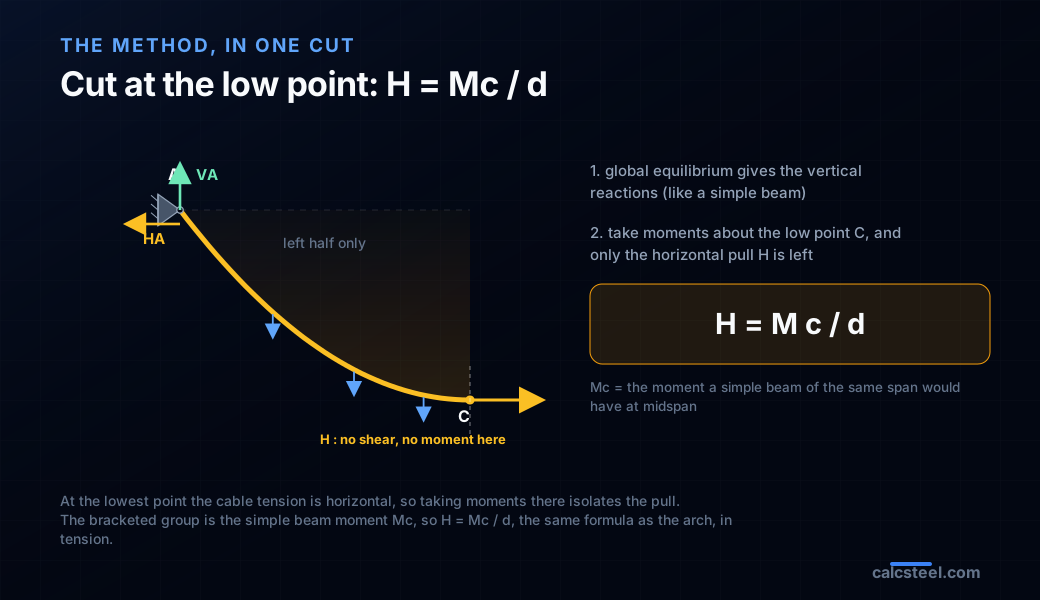
The solution reduces to two steps and one formula, and it is the tension twin of the arch. Step 1: the vertical reactions. Apply global equilibrium to the whole cable. Because both anchors are at the same level, the two horizontal pulls act along that same line and have zero moment arm about either support. Taking moments about one anchor therefore involves only the vertical reactions and the applied loads, exactly as it would for a straight simply supported beam of span L. So VA and VB come out identical to the simple-beam reactions. The cable's verticals are just the beam's verticals.
Step 2: the pull. Cut the cable at its low point and take one half as a free body. At the lowest point the tangent is horizontal, so the internal tension there is purely horizontal and equal to H, with no vertical component and no moment. Take moments about that cut point and the whole thing collapses. What remains is VA·(distance to the low point) minus the moment of the loads on that half, all balanced by H·d. Now notice that the first group is precisely the simple-beam bending moment at the low-point position, Mc. So the equation is Mc minus H·d = 0, which rearranges to H = Mc / d.
That is the same H = Mc / h the three-hinged arch uses for its thrust, with the sag d in place of the rise h. The arch turns Mc into compression pushing out; the cable turns the identical Mc into tension pulling in. Solve an imaginary straight beam, read one moment off it, divide by the sag, and you have the pull. Everything after this is arithmetic and interpretation.
Worked example 1: a point load makes a V
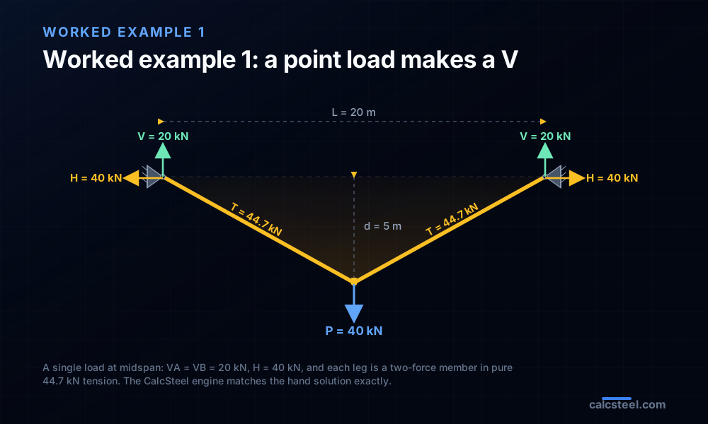
Take a cable anchored at two points L = 20 m apart at the same level, carrying a single vertical point load P = 40 kN at midspan, and hung so that the sag at the load is d = 5 m. With one concentrated load the funicular is the simplest polygon of all, a symmetric V of two straight segments. Run the recipe. The load sits at midspan, so by symmetry the vertical reactions split it evenly: VA = VB = P/2 = 20 kN.
Now the pull. The simple-beam moment at midspan under a central point load is the standard Mc = PL/4 = 40 × 20 / 4 = 200 kN·m. Divide by the sag: H = Mc / d = 200 / 5 = 40 kN. That is the whole solution by hand. Each anchor carries H = 40 kN pulling inward and V = 20 kN pulling down. Because each straight leg runs from an anchor to the load with nothing acting between, each leg is a two-force member in pure tension of magnitude √(40² + 20²) = 44.7 kN, constant along its length.
The CalcSteel engine, with the cable modeled as a two-segment chain and a moment release at the low point to enforce the flexible-cable condition, returns A (H = 40 kN, V = 20 kN) and B (H = 40 kN, V = 20 kN), a support tension of 44.7 kN, and zero bending everywhere, matching the hand solution to machine precision. Compare this with the arch: a central point load on a triangular three-hinged arch of the same span and rise gives the identical 40 kN, 20 kN, and 44.7 kN, but in compression. The cable is the arch reflected in a mirror.
Worked example 2: uniform load makes a parabola
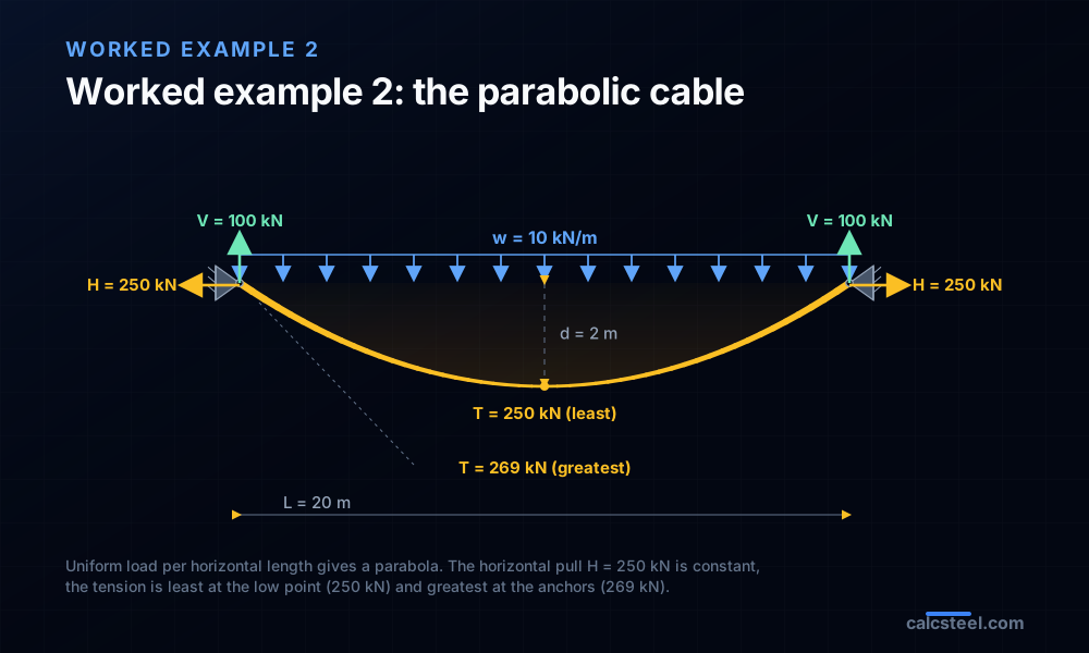
Now the case that carries most of the world's cables. A cable spanning L = 20 m carries a load w = 10 kN/m that is uniform per unit of horizontal length, the idealization of a suspension bridge deck hung from the main cable by many closely spaced vertical hangers. Hang it to a realistic sag d = 2 m, one tenth of the span. The vertical reactions are the simple-beam reactions for a full uniform load: VA = VB = wL/2 = 100 kN. The simple-beam moment at midspan is the standard Mc = wL²/8 = 10 × 20² / 8 = 500 kN·m, so the pull is H = Mc / d = 500 / 2 = 250 kN.
Under a load uniform per horizontal length the funicular is an exact parabola, and the engine confirms it: modeled as sixteen segments on the parabola with the low-point release, it reports essentially zero bending at every point and pure tension throughout, with reactions of 100 kN vertical and 250 kN horizontal at each anchor. This is the tension mirror of the funicular arch: match the shape to the load and bending disappears, leaving only the axial force the material is built for.
But the tension is not constant along the cable, and this trips up more students than any other point. The horizontal component H = 250 kN is constant, the same in every segment, because nothing applies a horizontal force between the anchors. The total tension is the resultant of that constant H and the vertical shear the cable carries, which grows from zero at the low point to the full reaction at the anchors. So the tension is least at the low point, where it equals H = 250 kN, and greatest at the anchors, where it reaches √(250² + 100²) = 269 kN. The cable is longer than the span, too: at this sag it measures about 20.52 m of cable to cross 20 m of gap. A cable is always most stressed where it meets its support.
Sag sets tension: the trade-off you actually design
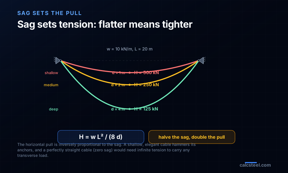
The formula H = wL²/(8d) hides a design decision that has consequences on every real cable structure. The pull is inversely proportional to the sag. Hold the span and the load fixed and the only free variable is how deep you let the cable hang, and that single choice sets the force in the cable and the force on the anchors.
Put numbers on it with the parabolic cable above, w = 10 kN/m over L = 20 m. At a deep sag of d = 4 m, the pull is H = 10 × 20² / (8 × 4) = 125 kN. Halve the sag to d = 2 m and the pull doubles to 250 kN. Halve it again to d = 1 m and it doubles again to 500 kN. The rule is exactly that blunt: halve the sag, double the pull. Push the logic to its limit and let the sag go to zero, and H goes to infinity: a perfectly straight cable cannot carry any transverse load at all, which is why no amount of tension will pull a clothesline flat.
So the sag is not an aesthetic afterthought, it is the main structural knob. A shallow, elegant cable looks light but hammers its anchors and stresses its own strands. A deep sag is gentle on everything but eats headroom, needs taller towers, and lengthens the cable. Every suspension bridge, every cable roof, every guy line is a chosen point on this trade-off, and the engineer who picks the sag is really picking the tension.
Worked example 3: self-weight makes a catenary
The parabola answers the suspension-bridge question, where the deck weight dwarfs the cable and hangs per horizontal metre. But a bare cable, a chain, a transmission line, a lightly loaded guy, carries mostly its own weight, and self-weight is uniform per unit length along the cable, not per horizontal metre. The extra cable in the steep parts near the anchors adds weight there, so the true shape is not a parabola but the catenary, from the Latin catena, chain.
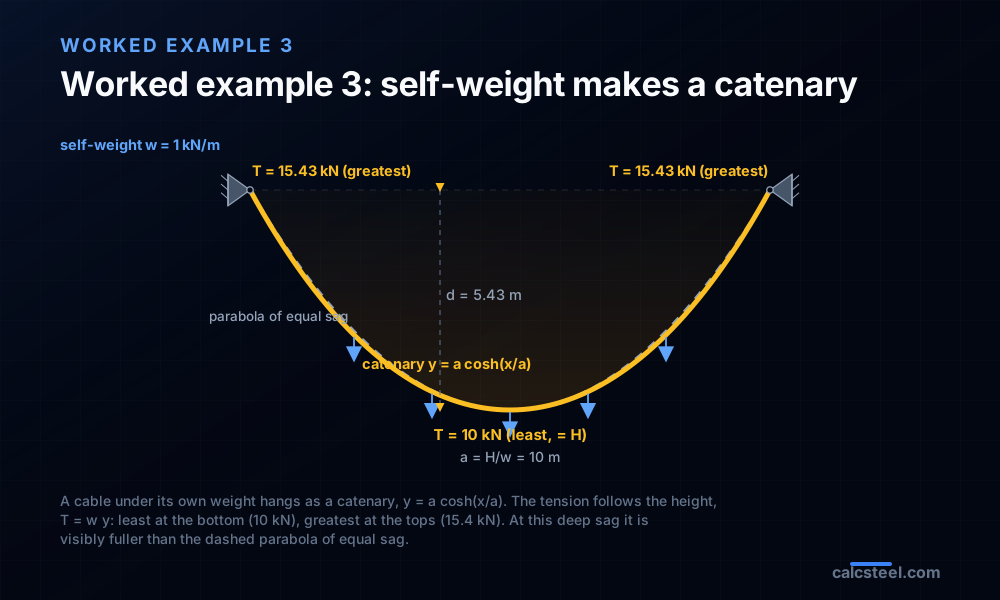
The catenary is the curve y = a·cosh(x/a), where a = H/w is the single parameter that sets its whole geometry, measured from the low point. Its tension law is beautifully simple: the tension at any point is T = w·y, proportional to the height of that point above the level where the tension would be purely horizontal. So the tension is least at the bottom and grows with height toward the anchors, and it never involves a square root or a shear calculation.
Work an example. Take L = 20 m, a cable of self-weight w = 1 kN/m, and choose the parameter a = 10 m. Then the horizontal pull is H = w·a = 10 kN at once. The sag follows from the shape, d = a·(cosh(L/2a) − 1) = 10 × (cosh(1) − 1) = 5.43 m, a deep hang. The tension is 10 kN at the low point (equal to H) and climbs to T = w·y at the tops, √(10² + 11.75²) = 15.43 kN, half again as much as at the bottom. The cable's own length is S = 2a·sinh(L/2a) = 23.50 m to cross a 20 m gap. The CalcSteel engine, with nodes placed on the exact catenary and the self-weight lumped by arc length, returns H = 10 kN, a support tension of 15.43 kN, and negligible bending, confirming every number.
Catenary or parabola: when does the difference matter?
Students often ask which curve is right, as if one were the truth and the other a mistake. Both are exact, for different loads. The parabola is exact when the load is uniform per horizontal length. The catenary is exact when the load is uniform per arc length, which is what self-weight is. A cable that is both loaded by a deck and heavy in itself lies somewhere between the two. So the honest question is not which is correct but how far apart they are, and that depends almost entirely on the sag.
Compare the two at equal span and equal sag under the same self-weight, and the numbers are decisive. At a shallow sag/span of 1/20, the catenary pull and the parabola pull differ by only 0.3%. At 1/10, the working sag of most structural cables, the gap is about 1.3%. At 1/8 it is 2%. Only when the cable hangs deep does the difference become real: 4.7% at 1/5, and 6.9% at 1/4, the deep hang of our catenary example.
That gives a clean rule of thumb. For a shallow cable, sag no more than about a tenth of the span, the parabola and the catenary agree to roughly a percent, and the parabola's simple algebra is entirely good enough for design. For a deep hang, a freely draped chain, a slack line, a decorative festoon, use the catenary, because the extra weight in the steep flanks genuinely changes both the shape and the tension. Shallow structural cables are parabolas for all practical purposes; deep hanging chains are true catenaries.
Try it: read Mc off a simple beam, then divide by the sag
The whole method reduces to one lookup: find the simple-beam bending moment at the low-point position, then divide by the sag. Everything else is arithmetic. The free CalcSteel shear and moment calculator below gives you that moment directly. Set the span, drop the same vertical loads the cable carries, and read Mc straight off the bending moment diagram at the low point's horizontal position. Then H = Mc / d.
Reproduce example 1 to get the feel: a 20 m simply supported span with a 40 kN load at midspan gives Mc = 200 kN·m, and 200 / 5 = 40 kN of pull. Or reproduce example 2: a 20 m span under 10 kN/m gives Mc = 500 kN·m, so H = 500 / 2 = 250 kN at 2 m of sag. Once you have H, the maximum tension at the anchor is just the resultant of H and the end reaction V, and the minimum tension at the low point is H itself. The calculator is the real solver, not a preview, and it runs in your browser with no login for the math.
|V| max
30 kN
@ x = 6 m
M max (sagging)
45 kN·m
@ x = 3 m
M min (hogging)
-0 kN·m
@ x = 6 m
Reactions (kN)
R_A 30 · R_B 30
Simply supported beam — uniformly distributed load
Segment equations — x in m, from the left end
0 m ≤ x ≤ 6 m
V(x) = 30 − 10·x [kN]
M(x) = 30·x − 5·x² [kN·m]
Profiles that resist this moment
Md = 45 kN·m → required Wx = Md / (fy/γa1) = 45 kN·m / (250/1.1) = 198 cm³
Bending screen (Wx ≥ Md/(fy/γa1), NBR 8800 γa1 = 1.10 — AISC 360 φb = 0.90 is nearly identical); plastic Zx is valid for compact sections only. δ is the elastic deflection of THIS loading with E = 200 GPa and the section's Ix (loads taken at service value). LTB, shear, compactness and code deflection limits are verified on the profile page and in the 3D editor. "Open in 3D editor" recreates THIS beam — span, supports and every load — with the profile already assigned.
A cable is an arch turned upside down
Everything above has been shadowing the arch on purpose, and now the reason is explicit. In 1675 Robert Hooke published the principle as an anagram whose solution reads: as hangs the flexible line, so but inverted stand the rigid arch. Hang a chain between two points and it finds, for free, the funicular of its load in pure tension. Invert that exact curve, freeze it rigid, and you have the ideal arch that carries the same load in pure compression. Tension becomes compression, the pull H becomes the thrust H, and the formula H = Mc / d is literally the same formula with the sag renamed the rise.
This is not a metaphor, it is a design tool. Antoni Gaudi hung weighted strings upside down to find the compression forms of the Sagrada Familia and the Colonia Guell crypt, reading the ideal arch directly off the hanging model. The funicular of any load is at once the perfect cable shape and, inverted, the perfect arch shape, which is why the parabola shows up as the ideal suspension cable and, flipped, as the ideal arch under a uniform deck.
The duality also carries the warning. An arch's thrust must land on a foundation that can resist being pushed apart, or on a tie between the springings. A cable's pull must land on an anchor that can resist being dragged together, or on a strut. The horizontal force never vanishes in either one, because it is the very mechanism that lets a curved line carry transverse load without bending. Respect the pull and the cable is the lightest structure you can build. Ignore it and the anchors move, the sag deepens, and the whole thing sheds its shape.
Where cables earn their keep
Cables win wherever tension is the efficient way to span, because a member that only pulls needs no material to resist buckling and can be spun from the highest-strength steel made. You find them as the main cables and hangers of suspension bridges and the stays of cable-stayed bridges; as the draped or radial cables of cable roofs over stadiums and arenas; as the guys that stabilize masts, towers, and temporary structures; as transmission lines strung between pylons, where the catenary sag has to be checked against clearance and against the extra tension of an ice load or a cold night; and as the tendons that pre-compress concrete, a cable buried inside a beam.
The advantages follow from the pure tension. A cable is extremely light for the load it carries, it uses steel at its full strength with no buckling penalty, and it is easy to erect by pulling rather than lifting a stiff member into place. The disadvantages are the other face of flexibility. A cable has almost no stiffness of its own, so it moves: it changes shape under moving or unsymmetrical load, it stretches elastically, and it can gallop or flutter in wind, which is why real cable structures are pre-tensioned, damped, or stiffened by a deck. And every cable structure lives or dies by its anchorage, the detail that has to catch the relentless pull.
One caution outranks all the others, and it is the same one the arch taught from the other side: the pull has to go somewhere. It must be delivered into an anchorage massive enough to resist being dragged inward, or caught by a tie or strut that closes the horizontal force within the structure, the way a bowstring closes the thrust of its arch. Ignoring H is the classic cable failure: the anchors creep together, the sag grows, the tension changes, and the geometry the whole design depended on quietly walks away.
Common mistakes and quick answers
Cables are simple to solve and easy to misread. These are the traps that catch students and practising engineers most often.
- Thinking the tension is constant. Only the horizontal component H is constant along the cable. The total tension is least at the low point (equal to H) and greatest at the anchors. Size the cable and the anchorage for the tension at the support, not at midspan.
- Using the wrong load measure. A parabola is funicular for load per unit horizontal length; a catenary for load per unit arc length (self-weight). Mixing them up puts the weight of the steep flanks in the wrong place. Shallow cables barely care, deep ones do.
- Forgetting the pull, or the anchor. The horizontal pull H never disappears and is often the largest force in the problem. It must be resisted by an anchorage or a tie. This is the single most expensive cable mistake.
- Believing a tighter cable is safer. The opposite. H = wL²/(8d), so reducing the sag raises the tension. A drum-tight cable is a high-tension cable, and a zero-sag cable needs infinite force.
- Expecting a cable to take compression or bending. It cannot. If your analysis puts a cable in compression, the real cable has gone slack and dropped out of the structure there, which is a geometry problem your linear model will not show you.
- How do I model it? Place the nodes on the funicular shape, pin both anchors, and release the moment at the low point so the chain is a flexible cable and not a stiff frame. A determinate, released model gives the pull exactly and independent of the section, just as a real cable is.
Key takeaways
- A cable carries load in pure tension, cannot take bending or compression, and therefore takes the funicular shape of its load: a polygon for point loads, a parabola for uniform load per horizontal length, a catenary for self-weight.
- The horizontal pull is H = Mc / d, the arch's thrust formula in tension, where Mc is the simple-beam moment at the low point and d is the sag. A 40 kN load at midspan of a 20 m cable with 5 m sag gives H = 40 kN, matched exactly by the engine.
- Sag sets tension: H = wL²/(8d), so halving the sag doubles the pull. A 10 kN/m load over 20 m pulls 250 kN at 2 m of sag, 500 kN at 1 m, and would need infinite tension at zero sag.
- Tension is not constant: least at the low point (equal to H), greatest at the anchors. The parabolic cable runs from 250 kN at midspan to 269 kN at the towers, so the anchor is where it is most stressed.
- Catenary and parabola agree to about 1% for shallow cables (sag under a tenth of the span) and diverge for deep hangs (about 7% at sag of a quarter of the span). Shallow structural cables are parabolas; deep chains are true catenaries.
- A cable is an arch turned upside down (Hooke, and Gaudi's hanging models). The pull never vanishes and must land in a capable anchorage or a tie, or the anchors creep together and the cable loses its shape.
Sources
Try CalcSteel for free
Model, analyze and design steel structures in your browser. No install, no signup.
Open the 3D editor