Static Determinacy and Stability: Counting Degrees Before You Model Anything

Before you place a single node, count the degrees. Static determinacy and stability decide whether equilibrium can solve your structure, whether it stands up at all, and which method you actually need. Worked beam, truss and frame examples, every number checked on a real FEM engine, with a free live calculator.
Key takeaways
- One count answers three questions: compare the unknowns you have (reactions, members) against the equilibrium equations available. Fewer means unstable, equal means statically determinate, more means indeterminate.
- Two master rules cover almost everything you draw: for a planar beam or frame compare the reactions r against 3 (the general form is 3m + r = 3n + c), and for a pin-jointed truss compare m + r against 2j.
- The degree of static indeterminacy is the surplus of unknowns over equations, and it is exactly the number of extra values a solver must find from compatibility, not from statics alone.
- Counting is necessary but not sufficient. A structure can satisfy the count and still collapse if its restraints are parallel or concurrent: geometric instability, the critical form a raw count will never catch.
- An unstable model is a singular stiffness matrix. The CalcSteel FEM engine reports it as a mechanism instead of returning a silent, wrong answer, which is exactly why the count is your pre-flight check.
Count the degrees before you model anything
Open any structural analysis course, Estruturas I or its equivalent anywhere in the world, and the very first skill it drills is not how to solve a beam. It is how to classify one. Before a single equation is written, you are taught to look at a structure and answer one question: is it a mechanism that will fall over, a determinate structure that statics alone can solve, or an indeterminate one that needs the stiffness of the members themselves to sort out the forces?
That classification is a thirty second count, and it decides everything that comes after. Skip it and you can spend an afternoon writing equilibrium equations for a frame that equilibrium can never solve, or worse, hand a solver a structure that is quietly a mechanism and trust the numbers it invents to keep it from failing.
This guide is the count, done properly. We take three real structures, a beam, a truss and a frame, count their degrees, then run each one through the same finite element engine that ships inside CalcSteel and watch the numbers confirm the classification to three decimals. Along the way there is a live calculator you can drive yourself.
We wrote it for three readers. If you are a student, this is the lecture that makes the rest of the course make sense. If you are a practising or self-employed calculista, it is the pre-flight check that stops a bad model before it costs you a day. And if you just want to know why software sometimes refuses to solve a frame, the answer is in the stability section.

What static determinacy and stability actually mean
Stability and determinacy are two separate questions, and you must ask them in that order. Stability asks whether the structure holds together as one rigid body under load, or whether some part of it can move freely as a mechanism. Determinacy asks a second, narrower question: if the structure is stable, can the equations of equilibrium alone find every reaction and internal force, or are there more unknowns than equations?
Equilibrium gives you a fixed budget of equations. In a plane, a rigid body has exactly three: the sum of horizontal forces is zero, the sum of vertical forces is zero, and the sum of moments about any point is zero (ΣFx = 0, ΣFy = 0, ΣM = 0). In three dimensions the budget is six. That budget is all statics will ever give you, and every classification below is just a comparison against it.
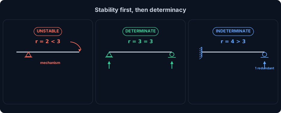
Three outcomes are possible, and every structure you will ever draw is one of them:
- Unstable (a mechanism). There are fewer independent restraints than the structure needs to stay put. Some displacement costs no strain energy, so the structure moves as a rigid mechanism. Equilibrium has no solution, or infinitely many. This is the one outcome you must never model and then trust.
- Statically determinate. The number of unknowns exactly equals the number of equilibrium equations. Statics alone finds every reaction and every internal force, no material properties required. A simply supported beam, a triangulated truss, a three-pinned arch: all determinate.
- Statically indeterminate (hyperstatic). There are more unknowns than equations. Equilibrium is necessary but no longer sufficient, and the surplus, the degree of indeterminacy, must be resolved from compatibility of displacements, which brings in the stiffness of the members. A propped cantilever, a continuous beam, a rigid portal frame: all indeterminate.
The important and often missed point is the ordering. Determinacy is only meaningful for a structure that is already stable. A count can come out looking perfectly determinate on a structure that is actually a mechanism, and that is the trap we return to near the end.
Where the counting rules came from
The idea that you can judge a structure by counting, before solving anything, is old and has a clear lineage. It is worth knowing, because it tells you the count is not a modern software shortcut. It is the theory the software automates.
- 1837, August Ferdinand Möbius shows that a bar count can balance and the structure can still be unstable, if the members fall into a special geometric arrangement. This is the first statement of the critical form, the reason counting is necessary but not sufficient.
- 1864, James Clerk Maxwell gives the rule still taught today for pin-jointed frames: a plane truss needs m = 2j − 3 members to be just stiff, which is the same as m + r = 2j once you count the r = 3 support reactions.
- ~1874, Otto Mohr and Heinrich Müller-Breslau formalise the analysis of both determinate and indeterminate structures, turning the count into a working design method.
- 1886, Lebrecht Henneberg gives systematic methods for building and checking determinate trusses, the bar-exchange method that resolves many critical forms.
- 1950s to 60s, matrix structural analysis and the finite element method absorb all of it. The degree of indeterminacy becomes the difference between the number of unknown displacements and the equations available, and the stiffness matrix does the compatibility bookkeeping automatically.
When a modern solver assembles its stiffness matrix and tries to factor it, it is testing exactly what Maxwell and Möbius described. A determinate or indeterminate stable structure gives an invertible matrix. A mechanism gives a singular one. The count you do by hand and the linear algebra the computer does are the same statement in two languages.
The count: reactions, members and equations
Here are the only formulas you need, and they all compare the unknowns in a structure against the equilibrium equations available.
Simple case: a single rigid body, count the reactions
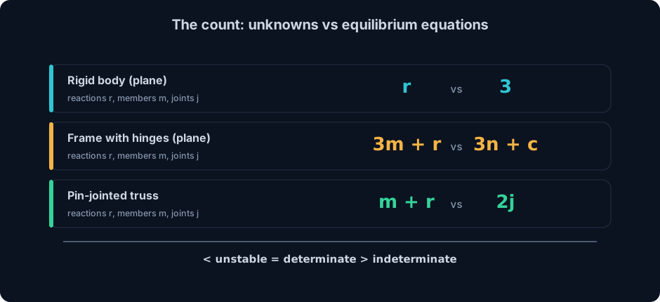
For a single rigid member or a simple frame with no internal hinges, in a plane you have three equilibrium equations, so you compare the number of support reactions r against 3:
- r < 3: unstable. Too few restraints, the body can still move.
- r = 3: statically determinate. Statics finds every reaction.
- r > 3: statically indeterminate to degree r − 3. That many reactions are redundant.
Count reactions by support type: a roller gives 1, a pin gives 2, a fixed (built-in) support gives 3. A simply supported beam is pin plus roller, r = 2 + 1 = 3, determinate. A propped cantilever is fixed plus roller, r = 3 + 1 = 4, indeterminate to the first degree.
General planar frame: members, nodes and hinges
When a frame has several members and internal hinges, use the general planar form. With m members, r reactions, n nodes and c condition equations (one per internal hinge that releases a moment):
Degree of static indeterminacy = (3m + r) − (3n + c)
Zero means determinate, positive means indeterminate to that degree, negative means unstable. Each internal hinge you add is one extra equation (one more c), which is why a three-pinned frame is determinate while the same frame welded rigid is not.
Pin-jointed truss: Maxwell's rule
A truss carries only axial force, so the equations are two per joint (ΣFx, ΣFy). With m members, r reactions and j joints:
m + r < 2j unstable, m + r = 2j determinate, m + r > 2j indeterminate to degree (m + r) − 2j.
In three dimensions the budgets grow: a space frame uses 6m + r against 6n + c, and a space truss uses m + r against 3j. The logic never changes, only the number of equations per node.
Worked example 1: the determinate beam, where statics is enough
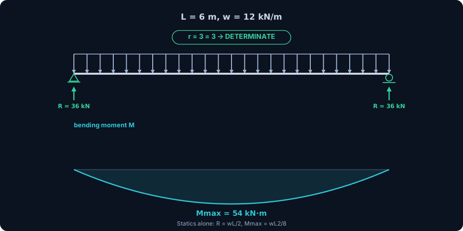
Start with the case the count calls determinate, so you can see statics deliver every number with nothing held back. Take a simply supported beam, span L = 6 m, under a uniform load w = 12 kN/m across its whole length. Pin at the left, roller at the right.
The count
Pin (2) plus roller (1) gives r = 3 reactions, against 3 planar equations. r = 3, so the beam is statically determinate, degree zero. Equilibrium alone should find everything, and it does.
Statics by hand
By symmetry, or by taking moments about either support, each reaction carries half the total load: R = wL / 2 = 12 × 6 / 2 = 36 kN at each end. The shear passes through zero at midspan, where the moment peaks at Mmax = wL² / 8 = 12 × 6² / 8 = 54 kN·m. That is the entire solution, and notice what it did not need: no section, no modulus of elasticity, no moment of inertia. A determinate structure does not care what it is made of to find its forces.
The engine agrees
Modelled in the CalcSteel FEM engine, the same beam returns RA = RB = 36.0 kN, Vmax = 36.0 kN and Mmax = 54.0 kN·m at midspan, an exact match to the hand calculation. This is the calibration case: when a solver nails the beam you can check by hand, you can trust it on the ones you cannot. If the reactions are where you want to start, our step-by-step guide to beam reaction forces and the primer on the free body diagram cover exactly this move.
Worked example 2: the determinate truss, m + r = 2j
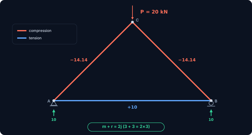
Trusses are where the counting rule earns its keep, because a truss can look busy and still be solvable by hand. Take the simplest complete one: a triangle with a pin at A (0, 0), a roller at B (4, 0) and an apex at C (2, 2), carrying a single point load P = 20 kN straight down at C.
The count
Members m = 3 (AC, CB, AB), reactions r = 3 (pin 2 plus roller 1), joints j = 3. Maxwell's rule: m + r = 3 + 3 = 6, and 2j = 2 × 3 = 6. They match, so the truss is statically determinate. Every bar force follows from joint equilibrium alone.
Method of joints
The vertical load splits evenly by symmetry, so RA = RB = 10 kN upward, with no horizontal reaction. At joint B the diagonal CB rises at 45°, so vertical equilibrium gives FCB = −10 / sin 45° = −14.14 kN, the minus sign meaning compression. Horizontal equilibrium at B then gives the bottom chord FAB = −FCB cos 45° = +10 kN, tension. By symmetry FAC = FCB = −14.14 kN.
The engine agrees, to the third decimal
Modelled as a genuine pin-jointed truss, the CalcSteel engine returns FAC = FCB = −14.142 kN (compression) and FAB = +10.000 kN (tension), with essentially zero bending in any member, exactly as two-force members should behave. It is the method of joints, reproduced to the third decimal.
Add one bar and the count flips
Now imagine adding a second diagonal so the triangle becomes a braced quadrilateral panel: m rises by one while j and r stay put, so m + r becomes 2j + 1. The truss is now indeterminate to the first degree, and no amount of joint equilibrium will find that extra bar force. You need compatibility, the same jump we make in the next example. For a full determinate truss solved on the engine and checked against the method of joints, see the 15 m roof truss worked example.
Try it: the reactions you can only get because it is determinate
The cleanest way to feel what determinacy buys you is to compute reactions yourself and watch statics do all the work. The calculator below is the real CalcSteel beam tool, embedded live on this page. Set a simply supported span, add a load, and read off the reactions and diagrams: every one of those numbers comes from equilibrium alone, precisely because the beam is determinate.
Then break it. Add a third support in the middle and the beam becomes a two-span continuous beam, indeterminate to the first degree. The reactions no longer split by simple statics, and the tool has to bring in the stiffness of the section to solve it. Same beam, one extra restraint, a completely different class of problem, and you can watch the moment redistribute the instant you add the support.
It is the real thing, free, with unlimited runs and no login for the math. If it opens in its own tab, here is the direct link to the free beam calculator. When you want the shear and moment diagrams drawn out in full, the shear and moment diagram calculator is the companion tool.
Max moment
45 kN·m
Max shear
30 kN
Max deflection
10.55 mm
= L/569
Bending stress σ
84.4 MPa
σ = M/Sx
Utilization
44.0%
NBR 8800 · δ ≤ L/250
Geometry & supports
Section
Ix 7999 cm⁴ · Sx 533 cm³ · 42.2 kg/m
Point loads (↓ positive)
None — add as many as you need.
Distributed loads (uniform or trapezoidal)
Model sketch
Diagrams — free PNG / SVG / CSV export, no watermark
Step-by-step — the calculation memory of YOUR beam
IPE 300 · L = 6 m · fy = 250 MPa
1. Reactions (equilibrium of the solved FEM model)
ΣFy = 0 · ΣM = 0
R_A = 30 kN · R_B = 30 kN
2. Peak shear (read from the SFD)
Vmax = |V(x)|max
Vmax = -30 kN @ x = 6 m
3. Peak moment (read from the BMD)
Mmax = |M(x)|max
Mmax = 45 kN·m @ x = 3 m
4. Peak deflection
EI = 15998 kN·m² (E = 200 GPa)
δmax = 10.55 mm @ x = 3 m = L/569
5. Elastic bending stress
σ = Mmax / Sx = 45.00 × 10³ / 533.3
σ = 84.4 MPa
6. Bending check — both codes, side by side
NBR 8800: σ ≤ fy/1.10 = 227.3 MPa · AISC 360: σ ≤ 0.90·fy = 225 MPa
NBR 37.1% PASS · AISC 37.5% PASS
7. Deflection check (serviceability — code-independent)
δ ≤ L/250 = 24 mm
10.55 mm / 24 mm = 44.0% PASS
Recomputed live from the current inputs by the direct-stiffness FEM engine — change any load and every step updates. Reproduce it by hand with the formulas in the sections below.
Lightest catalog profiles that pass (974 flexural candidates · NBR 8800)
| Profile | Std | Weight | Total steel | σ util | δ util | |
|---|---|---|---|---|---|---|
| W310x21 | AISC | 21 kg/m | 126 kg | 83% | 98% | |
| VS 300x23 | BR | 22.6 kg/m | 136 kg | 71% | 84% | |
| U 300x90x6.3 | BR | 23.1 kg/m | 139 kg | 82% | 98% | |
| U 300x100x6.3 | BR | 24.1 kg/m | 145 kg | 77% | 91% | |
| VS 250x25 | BR | 24.6 kg/m | 148 kg | 70% | 100% |
Elastic bending (σ = M/Sx vs fy/γa1, γa1 = 1.10 — NBR 8800) + deflection screening of the full flexural catalog. Lateral-torsional buckling, shear and local buckling are NOT checked here — run the full NBR 8800 / AISC 360 verification in the 3D editor.
Worked example 3: the indeterminate beam, one equation short
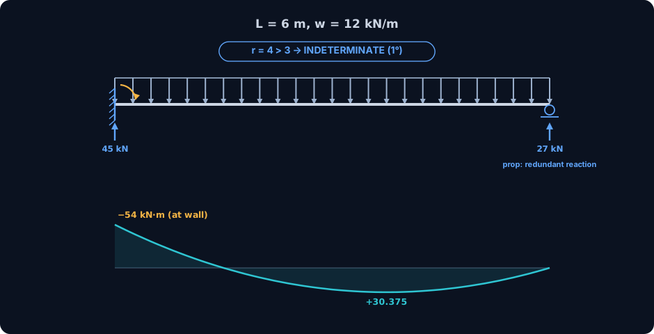
Now the case the count calls indeterminate, so you can see exactly where statics runs out. Take a propped cantilever: fixed at the left end, a roller prop at the right, span L = 6 m, same uniform load w = 12 kN/m.
The count
Fixed (3) plus roller (1) gives r = 4 reactions, against only 3 planar equations. r > 3, so the beam is statically indeterminate to the first degree. There is exactly one redundant reaction: three equations cannot pin down four unknowns, and the shortfall is one.
Why statics stops
Write the three equilibrium equations and you have three relations between four unknowns: the vertical reaction and fixing moment at the wall, and the vertical reaction at the prop. You can eliminate down to a single equation in two unknowns and then you are stuck. The missing information is not in equilibrium at all. It is in compatibility: the extra condition that the prop does not settle, so the deflection at that point must be zero. That condition brings in the beam's flexural stiffness EI, and only then does the system close. This is the exact border where hand statics ends and the stiffness method begins, walked through in detail in why the hand method stops and the matrix method starts.
What the engine finds
The CalcSteel engine solves the compatibility automatically and returns the classic textbook result: reaction at the prop RB = 3wL / 8 = 27.0 kN, vertical reaction at the wall 45.0 kN = 5wL / 8, and a fixing moment at the wall of −54.0 kN·m = −wL² / 8. The largest sagging moment in the span is 30.375 kN·m at x = 3.75 m, which is 9wL² / 128 at 5L / 8 from the wall, again an exact match to theory. Notice the fixing moment equals the full simply supported wL² / 8, but it now sits at the support as hogging, not at midspan as sagging: making the beam indeterminate moved the peak and flipped its sign. The same lesson on a continuous beam, with pattern loading, is in the indeterminate beam worked check.
The trap: counting is necessary, not sufficient
Here is the single most important thing on this page, and the one most people are never told clearly. A structure can pass the count and still be unstable. The formula m + r = 2j, or r = 3, is a necessary condition for determinacy. It is not sufficient for stability. The count checks that you have enough restraints. It does not check that they are arranged to do their job.
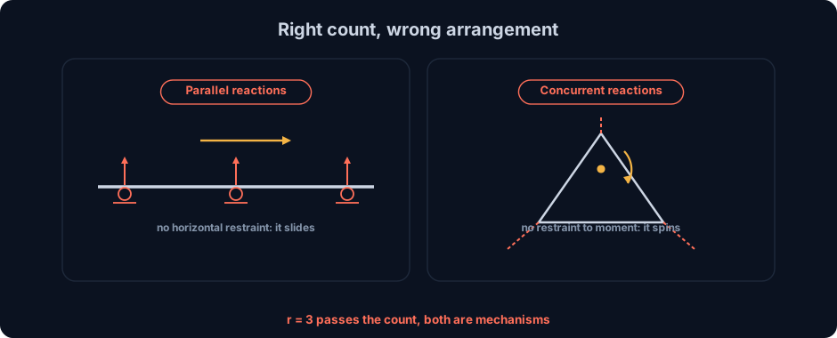
There are three classic ways to have the right number of restraints in the wrong arrangement, and every one of them is a mechanism your count will wave straight through:
- Parallel reactions. Support a beam on three rollers, all vertical. That is r = 3, matching the three planar equations, so the count says determinate. But all three reactions point the same way, so nothing resists a horizontal force, and the beam is free to slide sideways. It is a mechanism.
- Concurrent reactions. Arrange three reaction lines so they all pass through a single point. Again r = 3. But any applied moment about that common point has nothing to balance it, so the structure spins about the point. A mechanism again, hidden behind a perfect count.
- Critical form in a truss. Maxwell already knew this in 1864, and Möbius before him: a truss can satisfy m + r = 2j and still contain a panel that folds, if the members line up in a special geometry (three bars meeting collinearly at a joint, for instance). The count balances, the structure moves.
This is why the classification is stability first, determinacy second. You run the count, and then you look at the arrangement. Are the reactions non-parallel and non-concurrent? Is every joint properly triangulated? Only then does a matching count actually mean the structure stands.
Why the modeler cares: a singular stiffness matrix
Everything above has a direct consequence the moment you press Analyze. Inside any finite element solver, the structure becomes a stiffness matrix K, and solving for displacements means inverting it: K u = F. Stability and determinacy are not abstractions here. They are properties of that matrix.
- A stable structure, determinate or indeterminate, gives an invertible K. The solver factors it and returns one unique answer.
- An unstable structure gives a singular K. It cannot be inverted, because a mechanism is a displacement pattern that costs zero energy, a zero eigenvalue in the matrix. The solve either fails outright or, if the solver regularises to press on, returns enormous or arbitrary displacements that mean nothing.
This is the number one reason an analysis 'will not run' or spits out absurd deflections: the model is under-restrained somewhere, a support missing, a joint left as a hinge, a member floating free. The count you now know how to do by hand is the pre-flight that catches it before the solver does.
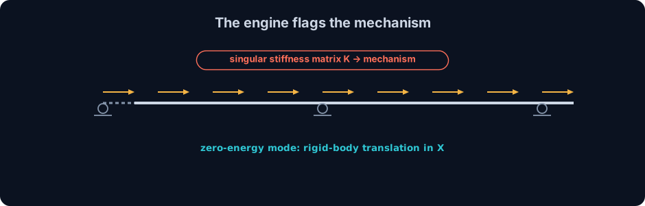
CalcSteel does not fail silently on this. When we take the three-roller beam from the previous section, r = 3 and passing the count, and hand it to the engine, the solver detects the singularity and reports it as a mechanism: a rigid-body translation in the horizontal direction, every node free to slide the same amount. It names the zero-energy mode rather than inventing forces to hide it. That is the whole value of the count made mechanical: the geometry your formula could not see, the linear algebra makes impossible to ignore. For the related question of how a stable frame can still be too flexible and sway toward instability, see notional loads and frame instability.
Common mistakes and FAQ
The count is simple, which is exactly why the errors are so consistent. Run this checklist before you trust any classification.
- Treating the count as proof of stability. m + r = 2j and r = 3 are necessary, not sufficient. Always follow the count with a look at the arrangement: parallel reactions, concurrent reactions, and truss critical forms all pass the count and still collapse.
- Miscounting a fixed support. In a plane a fixed (built-in) support is 3 reactions, not 2: two forces and a moment. A pin is 2, a roller is 1. Getting the fixed support wrong is the most common arithmetic slip in the whole method.
- Forgetting internal hinges. Every internal hinge that releases a moment adds a condition equation, one more c, which lowers the degree of indeterminacy by one. A three-pinned frame is determinate precisely because its extra hinges add the equations that its extra restraints would otherwise leave unmatched.
- Trying to hand-solve an indeterminate frame with statics. If the count says indeterminate, three equilibrium equations will never be enough. Do not keep writing equilibrium equations hoping one more appears. Switch to compatibility, or to a solver.
- Mixing up 2D and 3D equation budgets. A planar node gives 2 or 3 equations, a spatial node gives 6. Count in the dimension you are actually working in, or every verdict will be wrong.
Is m + r = 2j enough to know a truss is stable?
No. It is necessary but not sufficient. The equation confirms you have the right number of members and reactions, but not that they are arranged to resist load. A truss can satisfy m + r = 2j and still contain a collapsing panel (a critical form). Always pair the count with a check that every joint is properly triangulated and the reactions are neither parallel nor concurrent.
What exactly is the degree of static indeterminacy?
It is the number of unknowns in excess of the equilibrium equations available, equivalently the number of redundant restraints. A propped cantilever has degree 1, a fixed-fixed beam degree 3, a closed rigid frame degree 3 per closed loop. It is precisely the number of extra values a solver must find from compatibility rather than statics, and it is the single most useful number to know before you choose a method.
Does an indeterminate structure need material properties to solve?
Yes, and this is the sharpest practical difference. A determinate structure gives the same forces whatever it is made of, because statics alone fixes them. An indeterminate structure shares load according to relative stiffness, so its internal forces depend on E, I and A. That is why you can hand-solve a determinate truss on paper but need the section properties, and usually a solver, for an indeterminate frame.
Key takeaways
You have counted three real structures and watched the engine confirm every verdict. Here is what to carry away.
- One count, three questions. Compare unknowns against equilibrium equations. Fewer means unstable, equal means determinate, more means indeterminate, and the surplus is the degree.
- Two rules cover almost everything. For a planar beam or frame, r against 3, or (3m + r) against (3n + c) with hinges. For a pin-jointed truss, m + r against 2j. Six equations per node in space instead of three.
- Determinate means statics is enough. The 6 m beam gave R = 36 kN and M = 54 kN·m, the triangle truss gave 14.14 kN and 10 kN, all from equilibrium alone, all matched by the engine.
- Indeterminate means compatibility joins in. The propped cantilever, r = 4, needed the zero-deflection condition at the prop to close, and returned 27 kN and a hogging 54 kN·m that no pure statics could find.
- Counting is necessary, not sufficient. Parallel or concurrent reactions and truss critical forms pass the count and still fail. An unstable model is a singular stiffness matrix, and the CalcSteel engine reports it as a mechanism instead of a silent wrong answer.
Now stop reading and start counting. Drop your own beam into the free beam calculator, add and remove supports, and watch a determinate structure turn indeterminate under your hands. When you are ready for the full building, CalcSteel runs the same real FEM engine on complete frames and trusses right in your browser, on a genuinely free plan, with every reaction, diagram and code check included. Students get everything unlocked through CalcSteel Education, free.
Sources
Try CalcSteel for free
Model, analyze and design steel structures in your browser. No install, no signup.
Open the 3D editor