Beam Reaction Forces: Calculate Step by Step

Learn how to calculate beam reaction forces using equilibrium equations. Covers pin, roller and fixed supports, plus statically indeterminate propped cantilevers and continuous beams, with worked examples verified by the CalcSteel engine.
Key takeaways
- Reactions are found first — they are the starting point for every shear, moment, deflection, and connection calculation.
- A 2D beam obeys three equilibrium equations (ΣF_x = 0, ΣF_y = 0, ΣM = 0), which solve up to three unknown reaction components.
- Support type sets the reaction count: a roller gives 1, a pin gives 2, and a fixed support gives 3 (including a moment reaction).
- Take moments about a support to eliminate its own reactions, then verify by summing moments about a second point.
- Three unknowns with three equations is statically determinate; more unknowns make the beam indeterminate and require the stiffness method.
- A statically indeterminate beam (a propped cantilever or a continuous beam) has more reactions than equilibrium can solve; the redundant reactions follow from compatibility of displacements (the flexibility or stiffness method), not statics alone.
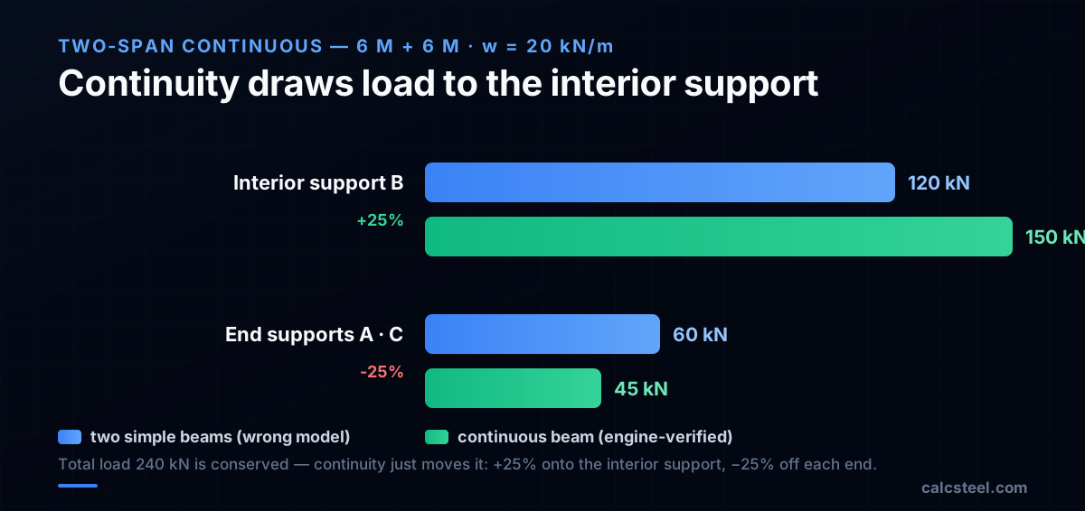
- Continuity draws load toward interior supports: a two-span beam under uniform load reacts 3wL/8 at each end and 5wL/4 over the interior support, about 25% more on the interior support than a two-simple-beam shortcut predicts.
What are beam reaction forces and why do you need them?
Reaction forces are the forces that supports exert on a beam to keep it in equilibrium. Every structural analysis begins with finding the reactions because they are the starting point for drawing shear force and bending moment diagrams.
Without correct reactions, every subsequent calculation — shear, moment, deflection, member sizing — will be wrong. Reactions are also the forces that the beam transfers to its supporting columns, walls, or foundations, so they directly determine the design of the support structure below.
For a 2D beam in the plane, three equilibrium conditions must be satisfied:
- ΣF_x = 0 — The sum of all horizontal forces equals zero
- ΣF_y = 0 — The sum of all vertical forces equals zero
- ΣM = 0 — The sum of moments about any point equals zero
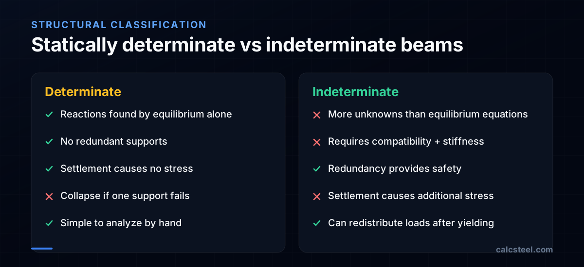
These three equations can solve for up to three unknown reaction components. If there are exactly three unknowns, the beam is statically determinate. If there are more, the beam is statically indeterminate and requires additional compatibility equations.

What types of supports are used for beams?
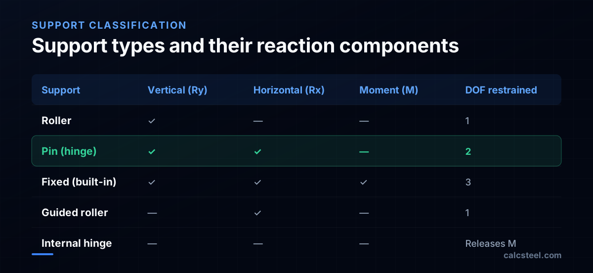
The type of support determines how many reaction components exist at that point:
Roller support
- Provides one reaction: vertical force (R_y)
- Allows horizontal movement and rotation
- Symbol: a triangle resting on a surface
- Example: one end of a bridge girder sitting on an expansion bearing
Pin (hinge) support
- Provides two reactions: vertical (R_y) and horizontal (R_x)
- Allows rotation but prevents translation in all directions
- Symbol: a triangle fixed to the ground
- Example: a gusset plate bolted to a support with a single bolt line
Fixed (built-in) support
- Provides three reactions: vertical (R_y), horizontal (R_x), and moment (M)
- Prevents all movement and rotation
- Symbol: a hatched wall
- Example: a cantilever beam welded to a column with a moment connection
Choosing supports for determinate analysis
A simply supported beam uses one pin + one roller = 3 unknowns (2 from pin + 1 from roller) = solvable with 3 equilibrium equations.
A cantilever uses one fixed support = 3 unknowns = solvable.
A propped cantilever uses one fixed + one roller = 4 unknowns = indeterminate (need one compatibility equation).
How do you calculate reactions for a simply supported beam with uniform load?
This is the most common case in structural engineering practice.
Example — 8 m beam with w = 15 kN/m
Supports: pin at A (left), roller at B (right)
Step 1 — Draw the free body diagram Replace supports with reaction forces: R_Ax (horizontal at pin), R_Ay (vertical at pin), R_By (vertical at roller).
Step 2 — Sum horizontal forces ΣF_x = 0: R_Ax = 0 (no horizontal loads applied)
Step 3 — Sum moments about A ΣM_A = 0: R_By × 8 − (15 × 8) × 4 = 0 R_By × 8 = 480 R_By = 60 kN ↑
Step 4 — Sum vertical forces ΣF_y = 0: R_Ay + R_By − 15 × 8 = 0 R_Ay = 120 − 60 = 60 kN ↑
Check: For a symmetric beam with symmetric loading, R_Ay = R_By = wL/2. ✓
Why take moments about A?
Taking moments about A eliminates R_Ax and R_Ay from the moment equation, leaving only R_By as the unknown. This gives a direct solution without needing to solve simultaneous equations. Always choose your moment center to eliminate as many unknowns as possible.
CalcSteel tip: The analysis engine computes reactions automatically for any number of supports and any load combination. But hand-checking the reactions is the fastest way to verify your model is correct. You can run this exact 8 m example in the free beam reaction calculator — no signup required — and compare its reactions against your hand solution.

How do you find reactions for a beam with multiple point loads?
When several concentrated loads act on the beam, sum their individual contributions:
Example — 10 m beam with P₁ = 40 kN at 3 m and P₂ = 60 kN at 7 m
Pin at A, roller at B.
Sum moments about A: ΣM_A = 0: R_B × 10 − 40 × 3 − 60 × 7 = 0 R_B × 10 = 120 + 420 = 540 R_B = 54 kN ↑
Sum vertical forces: R_A = 40 + 60 − 54 = 46 kN ↑
Verification — sum moments about B: ΣM_B = R_A × 10 − 40 × 7 − 60 × 3 = 460 − 280 − 180 = 0 ✓
Always verify by summing moments about a different point. If the result is not zero, there is an arithmetic error.
Influence of load position
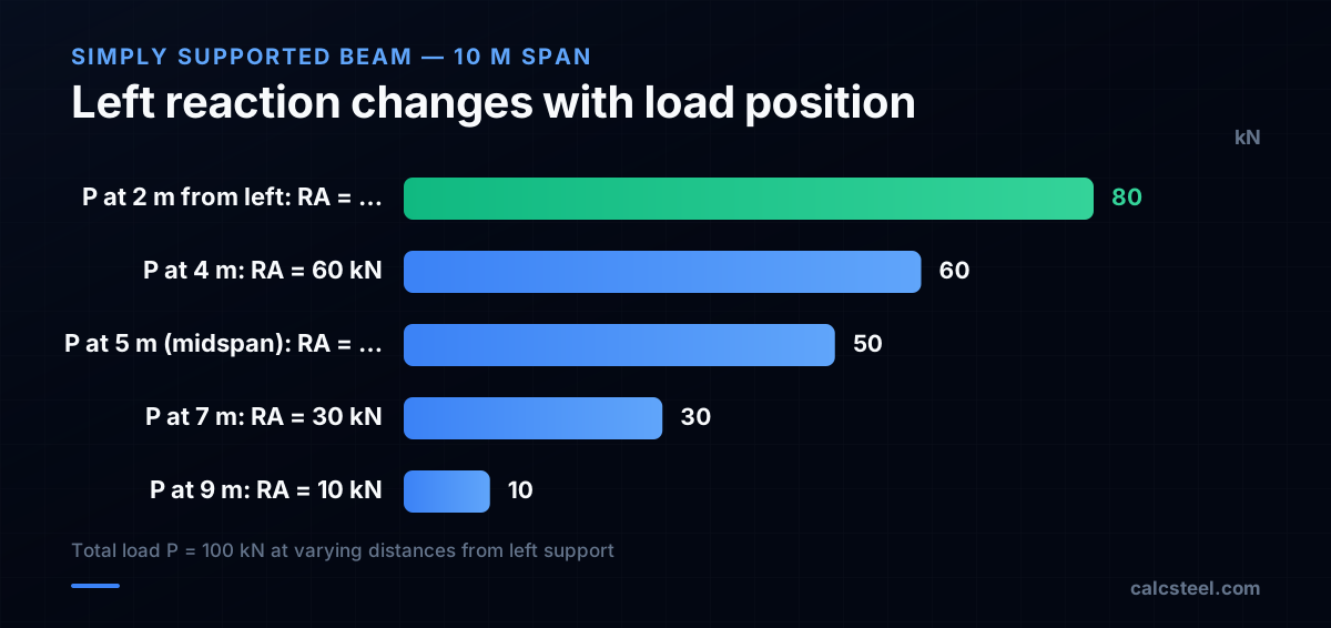
For a single load P on a simply supported beam:
- R_A = P × b / L (where b = distance from load to B)
- R_B = P × a / L (where a = distance from load to A)
The closer the load is to a support, the larger the reaction at that support. A load directly over support A gives R_A = P and R_B = 0.
How do you calculate reactions for a cantilever beam?
A cantilever beam has one fixed support and one free end. The fixed support must resist all vertical force, horizontal force, and moment.
Example — 5 m cantilever with w = 12 kN/m
Fixed support at A, free end at B.
Sum vertical forces: ΣF_y = 0: R_Ay − 12 × 5 = 0 R_Ay = 60 kN ↑
Sum moments about A: ΣM_A = 0: M_A − (12 × 5) × 2.5 = 0 M_A = 150 kN·m (counterclockwise)
The fixed support moment M_A resists the tendency of the beam to rotate downward. This moment is the maximum bending moment in the beam and occurs at the support.
Cantilever with point load at free end
For P = 30 kN at the free end of a 4 m cantilever:
- R_Ay = P = 30 kN
- M_A = P × L = 30 × 4 = 120 kN·m
Key difference from simply supported beams
Cantilever reactions include a moment reaction. This moment must be transferred through the connection to the supporting structure. A bolted end plate or welded moment connection is required — a simple shear connection (clip angle) cannot resist this moment and would fail.
Multiple loads on a cantilever
For multiple loads, sum each force and its moment about the support:
- R_Ay = ΣP_i + Σ(w_i × L_i)
- M_A = ΣP_i × d_i + Σ(w_i × L_i × d̄_i)
where d_i is the distance from each load to the support.

How do you handle overhanging beams and internal hinges?
Overhanging beams extend beyond one or both supports. The overhang creates a negative moment region over the support.
Overhanging beam example
Beam with pin at A (x = 0), roller at B (x = 8 m), and overhang to C (x = 11 m). Uniform load w = 10 kN/m over the entire length.
Sum moments about A: ΣM_A = 0: R_B × 8 − (10 × 11) × 5.5 = 0 R_B = 605 / 8 = 75.6 kN ↑
Sum vertical forces: R_A = 10 × 11 − 75.6 = 34.4 kN ↑
Notice R_B > wL/2 because the overhang load adds lever arm. The reaction at A is reduced — if the overhang is long enough, R_A can become negative (upward load needed to prevent tipping), requiring a tie-down anchor.
Internal hinges
An internal hinge releases the moment at a specific point, adding one equation (M = 0 at the hinge) and one unknown. This makes structures like three-hinged arches statically determinate.
For a beam with an internal hinge:
- Cut the beam at the hinge
- Draw free body diagrams of both sides
- Apply ΣF_x = 0, ΣF_y = 0, ΣM = 0 for each side
- Plus M = 0 at the hinge (compatibility)
This gives 7 equations for 7 unknowns (4 reactions + 3 internal forces at the hinge).
How do you find reactions when the beam is statically indeterminate?
Every example so far has been statically determinate: three equilibrium equations, three unknown reactions, done. Add one more support and equilibrium runs out of equations. A propped cantilever (fixed at one end, resting on a roller at the other) has four reaction components (R_Ax, R_Ay, M_A and R_By) but still only three equations. The beam is statically indeterminate.
The degree of static indeterminacy (DSI) counts the surplus:
DSI = (reaction components) − (3 equilibrium equations + condition equations)
A condition equation is an extra equation released by an internal hinge (M = 0 at the hinge). A propped cantilever has DSI = 4 − 3 = 1, so it has one redundant reaction. The two-span continuous beam in the next section is also DSI = 1.
The flexibility (force) method in four steps
- Pick as many redundant reactions as the DSI and remove them, leaving a released structure that is statically determinate.
- Solve the released structure under the real load and find the displacement at each removed restraint (call it δ₁₀).
- Apply a unit value of each redundant on the released structure and find the displacement it produces (δ₁₁).
- Enforce compatibility: the real support allows no movement there, so δ₁₀ + R·δ₁₁ = 0. Solve for the redundant, then finish with statics.
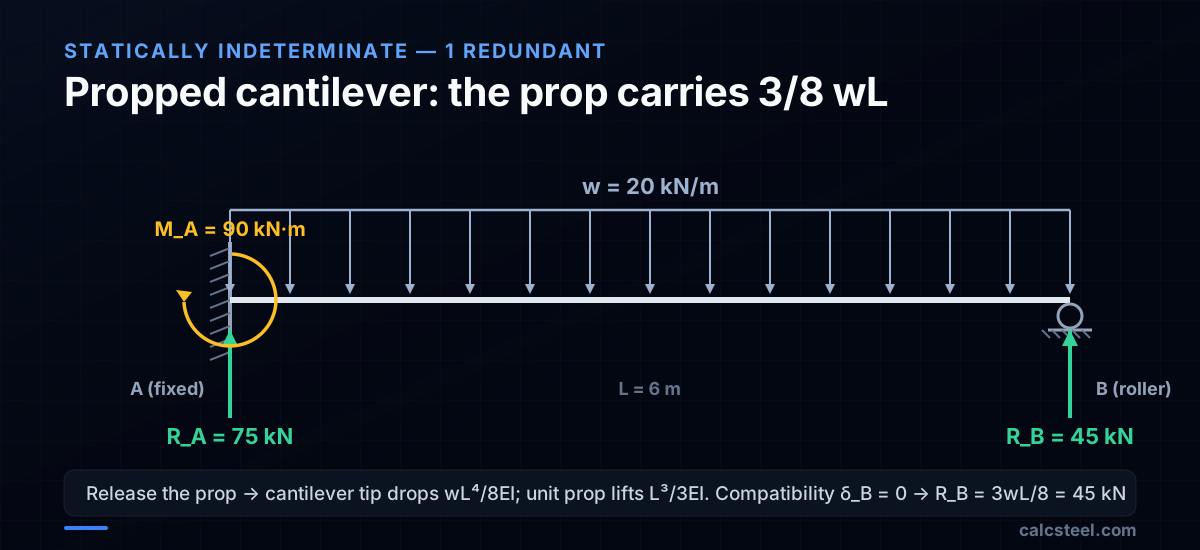
Worked example: propped cantilever, w = 20 kN/m, L = 6 m
Fixed support at A, roller prop at B. DSI = 1, so take the prop reaction R_B as the redundant. Removing the roller leaves a plain cantilever fixed at A and free at B, which is determinate.
Step 1. Deflection under the real load. The free tip of a cantilever under a full-span UDL drops δ₁₀ = wL⁴/8EI.
Step 2. Deflection under a unit redundant. A unit upward force at the tip lifts it δ₁₁ = L³/3EI.
Step 3. Compatibility. The real roller permits no vertical movement, so the net tip deflection is zero: wL⁴/8EI = R_B × L³/3EI. The EI cancels, giving R_B = 3wL/8 = 3 × 20 × 6 / 8 = 45 kN ↑.
Step 4. Finish with equilibrium. R_A = wL − R_B = 120 − 45 = 75 kN ↑. Taking moments about A, M_A = wL²/2 − R_B × L = 360 − 270 = 90 kN·m.
The prop takes only 3/8 of the total load, not half. The fixed end keeps the other 5/8 plus a 90 kN·m clamping moment. Running this exact model in CalcSteel's stiffness solver returns R_A = 75 kN, R_B = 45 kN and M_A = 90 kN·m, matching the hand solution to three decimals.
How do you find reactions for a two-span continuous beam?
A continuous beam runs over three or more supports with no internal hinges between them. It is the most common indeterminate beam in real floors and bridges. A two-span beam on three simple supports has four vertical reaction components and three equations, so DSI = 1: one redundant, usually taken as the bending moment over the interior support.
The three-moment equation
Clapeyron's three-moment equation is the classic hand tool. It relates the support moments over three consecutive supports. For two equal spans L carrying the same UDL w, with moment-free ends M_A = M_C = 0, it collapses to:
2·M_B·(2L) = −(wL³/4 + wL³/4), so M_B = −wL²/8
For L = 6 m and w = 20 kN/m: M_B = −20 × 6² / 8 = −90 kN·m, a hogging moment that puts the top fibre in tension over the interior support.
From the interior moment to the reactions
Each span now carries its UDL plus that interior hogging moment. Span equilibrium gives:
- R_A = R_C = wL/2 − |M_B|/L = 60 − 90/6 = 45 kN ↑
- R_B = 2wL − R_A − R_C = 240 − 45 − 45 = 150 kN ↑ (= 5wL/4)
Check: 45 + 150 + 45 = 240 kN = w × 2L. ✓ CalcSteel returns exactly 45 / 150 / 45 kN for this model.
Why continuity changes the design below
A tempting shortcut is to treat the two spans as two independent simply supported beams sharing the middle support. That gives R_middle = wL/2 + wL/2 = 120 kN and R_end = 60 kN, and it is wrong. The real continuous beam puts 150 kN on the interior support (+25%) and only 45 kN on each end (−25%). The total 240 kN is unchanged, so continuity simply draws the load inward.
The consequences flow straight into the design:
- Sizing the interior column and its footing for 120 kN instead of 150 kN under-loads them by 25%.
- The hogging moment puts the top fibre in tension and the bottom flange in compression over the support, so negative-moment detailing and bottom-flange bracing against lateral-torsional buckling are governed there, not at midspan.
- Because the beam is indeterminate, support settlement induces reactions even with no load, which a determinate beam never does. A dip at the interior support redistributes all three reactions again.
CalcSteel solves this directly for any number of spans and any load pattern, so you never hand-redistribute. But knowing 45 / 150 / 45 lets you spot-check the interior support, which is exactly where a determinate assumption fails.
What are common mistakes when calculating beam reactions?
1. Wrong sign convention
Pick a consistent sign convention (e.g., up = positive, counterclockwise moment = positive) and stick to it. Mixing conventions within the same problem gives wrong results.
2. Forgetting a reaction component
A pin has two reactions (vertical + horizontal), not one. Even when there are no horizontal loads, R_x at the pin exists — it just equals zero. Including it in your free body diagram avoids missing horizontal equilibrium when inclined loads are present.
3. Wrong moment arm for distributed loads
A uniform load w over length L acts as a resultant force wL at the centroid (L/2 from the start). A triangular load acts at L/3 from the heavy end. Using the wrong centroid location gives incorrect reactions.
4. Not verifying the result
Always check reactions by summing moments about a point you did NOT use in the calculation. If ΣM ≠ 0, there is an error.
5. Confusing internal forces with reactions
Reactions are external forces at supports. Internal forces (V, M, N) are found AFTER reactions by cutting the beam. Do not mix them.
6. Treating indeterminate beams as determinate
A continuous beam over three supports has four reaction components but only three equilibrium equations. You cannot solve it with statics alone — you need the stiffness method or moment distribution.

How does CalcSteel compute beam reactions?
CalcSteel uses the direct stiffness method to compute all reactions simultaneously for any structure — determinate or indeterminate, any number of supports, any loading.
Reaction output
After analysis, the reactions panel shows:
- Vertical, horizontal, and moment reactions at every support
- Reactions for each individual load combination
- The governing combination for foundation design
- Envelope values (maximum and minimum) across all combinations
Foundation design data
The reaction values feed directly into foundation design:
- Column base plates are sized for the maximum compressive reaction
- Anchor bolts are designed for the maximum tensile reaction (uplift)
- Foundation pads are sized for the maximum bearing pressure
Reaction verification
The results include a global equilibrium check: the sum of all reactions equals the sum of all applied loads. Any imbalance indicates a modeling error (missing support, disconnected member, or load applied to a free node).
For simple structures, verify CalcSteel's reactions with a hand calculation. For complex structures with many load combinations, the software handles thousands of equilibrium solutions that would be impractical by hand — but always spot-check a few key combinations.

Sources
Try CalcSteel for free
Model, analyze and design steel structures in your browser. No install, no signup.
Open the 3D editor