Column Splices: Where to Put It and What Has to Cross It

A column splice is a cut you choose, not one the column forces on you. Two decisions define it: where to put it up the height of the column, and what has to cross it. The instinct is to size the splice for the axial load the column carries, which on a real building runs well past a thousand kilonewtons. That instinct sends you down the wrong path, because on a column finished to bear almost all of that compression takes the short way across the joint through direct bearing and never touches a plate or a bolt. What the connectors actually carry is far smaller and comes from somewhere else: the tension a load combination can open up, the shear the frame passes through the story, the flange force from any moment, and a minimum the code insists on even when the analysis says the force is nearly zero. This guide places one splice on a real heavy column, runs the demand on the CalcSteel engine, and shows that the piece of steel that sizes it is never the 1400 kN of compression everyone stares at.
Key takeaways
- A column splice is located about 1.2 m (4 ft) above the finished floor, above the beam-to-column connection and near the column inflection point where the moment is low. It is a decision about erector access and about where the demand is smallest, not about where the column is weakest.
- On a column finished to bear, compression crosses the joint by direct bearing. On the worked heavy H-section the milled contact clears the 1400 kN of factored compression 5.3 times over, so the splice plates and bolts carry almost none of it. The biggest force in the column is the one the connectors never see.
- What the connectors carry is the tension, the shear and the moment. The 120 kN.m column moment resolves into a 353 kN flange force through the couple Ff = M/(d - tf), and that, not the axial, sizes the flange plates: two 300 x 16 mm plates with six M20 bolts a side land at 67 percent.
- The code sets a minimum the analysis does not. In a building designed to AISC 341, every column splice must cross a shear of Mpc / (as x H), the column plastic moment over the storey height, here 225 kN, which is 3.75 times the 60 kN the frame analysis delivers. The web plates are sized by the code, not by the model.
- A partial-penetration groove-welded splice is designed for twice its required strength under the seismic provisions, and a splice between two different column sizes needs a fill plate with the bearing limited to the smaller section. The detail is decided by rules, not by the reaction.
A cut you choose
A beam splice happens where the beam runs out of length. A column splice is different: the column could be rolled in one piece for three or four storeys, and you cut it anyway, on purpose, because a 12 m stick is awkward to ship, to raise and to stand. So the splice is a decision, and it comes in two parts that people tend to answer as one. The first is where, up the height of the column, to put it. The second is what, of all the forces the column carries, actually has to cross the cut.
The trap is to answer the second question with the axial load, because that is the number on the column schedule and it is large. On a real building a column at a low floor carries well over a thousand kilonewtons in compression, and the reflex is to size the splice to pass all of it. That reflex is wrong twice over. It is wrong because a column finished to bear passes almost all of its compression straight across the milled joint without loading a single plate, and it is wrong because the things that do load the plates, tension, shear and moment, are smaller, come from the lateral system and the load combinations, and include a floor the code sets that the analysis never reaches. This guide takes one splice on one heavy column and sizes it end to end, and the section of steel that decides it is never the compression.
What a column splice actually is
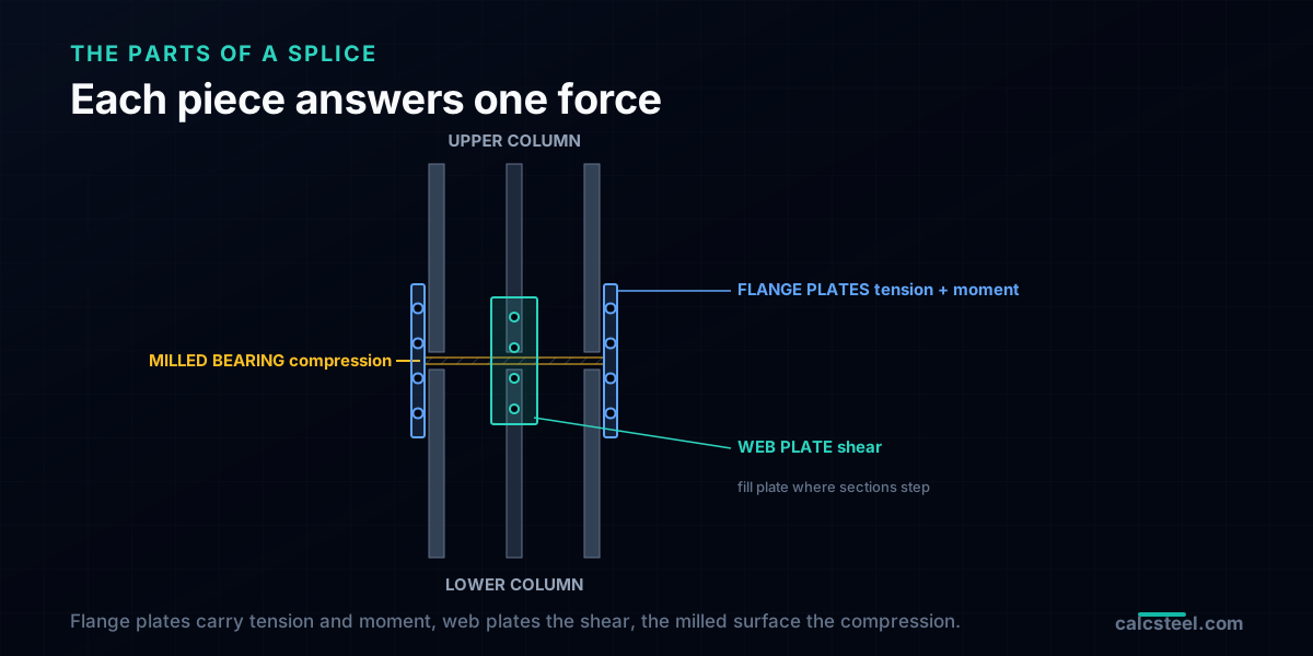
Strip the splice to its parts. Two column shafts meet end to end, an upper length and a lower one, usually a lighter section over a heavier one because the load sheds as you climb. Across the joint go three kinds of material. Flange plates, one on each face of each flange, tie the flanges of the two shafts together and carry any tension and the flange force from moment. A web plate, or a pair of them, ties the webs and carries the shear. And where the two ends are milled flat and set in contact, the bearing surface itself carries compression directly, steel to steel, with the plates only holding the pieces in line.
The connectors are bolts or welds. A bolted splice uses high-strength bolts through the flange and web plates and goes up fast in the field. A welded splice uses groove welds, full or partial penetration, across the flanges and sometimes the web. When the upper shaft is a different size from the lower one, a fill plate (a division or shim plate) packs the step so the plates sit flat and the ends bear. Every one of these pieces exists to answer a specific one of the forces crossing the cut, which is why naming the forces first, and not the section, is the whole discipline. For the base of the same column, where the load leaves the steel and enters concrete, the companion column base plate guide covers the joint at the other end.
Where to put it: about 1.2 m up, and why
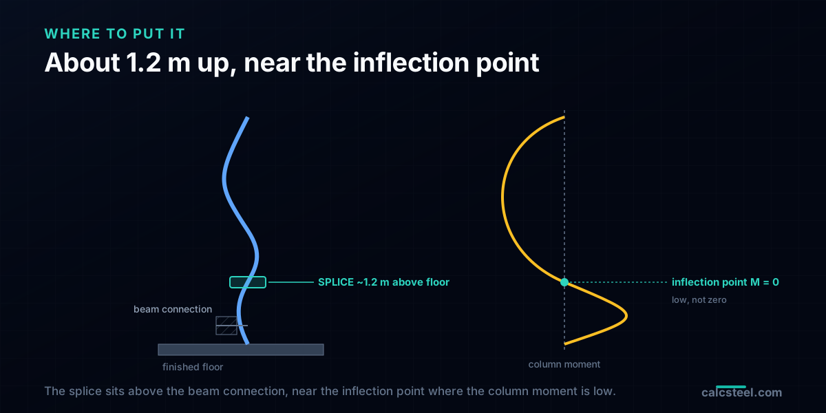
The standard place for a column splice is roughly 1.2 m (4 ft) above the finished floor, and each part of that sentence is a reason. It is above the floor, not at it, so the erector has a working platform: at that height a person can stand on the deck and reach the bolts or the weld, which is a safety and a productivity rule before it is a structural one. It is above the beam-to-column connection, so the splice sits in the clear length of the column and does not collide with the shear tabs, the moment plates and the stiffeners crowded around the floor level. And it is near the point of contraflexure, the height in the storey where the column's bending moment passes through zero as it bends in double curvature under lateral load, so the splice lands where the moment it has to cross is close to its smallest.
Seismic design pins this down instead of leaving it to habit. The AISC Seismic Provisions require the splice to sit at least 1.2 m (4 ft) from the beam-to-column flange connections, so it stays out of the region where the column is expected to yield, with the splice dropped to the column mid-height only where the clear storey is under 2.4 m. The familiar phrase 1.2 m above the finished floor is really an access rule wearing the same number: a User Note recommends that height so the crew can rig the perimeter safety cables before the next tier goes up. Structure and safety land on roughly the same place. Note what none of this logic says: it never puts the splice where the force is zero. The moment is low near the inflection point, not absent, the axial is barely changed by a metre of height, and the shear the storey carries is there the whole way up. A splice sits where it is convenient and where the demand is modest, and then it is designed for the demand that is actually there, which is the subject of the rest of this guide. The inflection point and the clear length also set the column's effective length, the other reason this height matters.
What has to cross it: four forces, not one
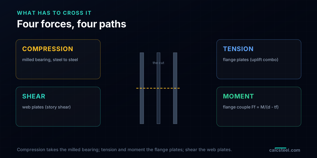
Make the cut and look at what has to pass through it. There are four things, and they take different paths and are carried by different pieces of steel:
1. Compression. The axial load the column sheds downward. If the ends are finished to bear it crosses steel to steel through the milled contact, and the plates carry almost none of it. If the ends are not milled, the plates and their connectors carry all of it, which is why milling is worth it on a heavy column.
2. Tension. Not from gravity, which only ever compresses a column, but from a load combination that lifts: wind or seismic overturning under a combination like 0.9D + 1.0W can put a tall column's windward side into net tension. Only the flange plates and their bolts can cross a tension, so this is the force that makes the plates non-optional.
3. Shear. The storey shear the lateral system passes through the column, carried across the cut by the web plates.
4. Moment. Any bending at the splice height, resolved into a couple: a tension force in one flange and an equal compression in the other, each equal to the moment divided by the distance between the flanges. The flange plates carry it.
Reading the four this way is the reframe the title promises. The compression is the largest force and the least of your problems, because it has a path that avoids the connectors entirely. The connectors exist for the other three, plus a code minimum, and those are what set the plate sizes. The way the factored combinations turn wind and gravity into the governing tension and moment at the splice is the job of the load combination that produces them.
Compression takes the short way
Start with the biggest number, because it is the one that leaves the fastest. When the two column ends are finished to bear, that is, milled or saw-cut flat to a plane, the compression passes from the upper shaft to the lower one as direct bearing, steel pressing on steel over the whole cross-sectional area of contact. AISC 360 lets you transfer compression this way and gives the bearing strength as Rn = 1.8 Fy Apb, where Apb is the contact area, with a resistance factor of 0.75.
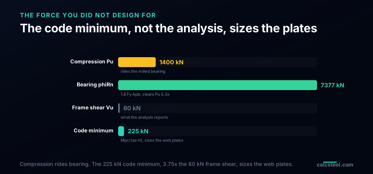
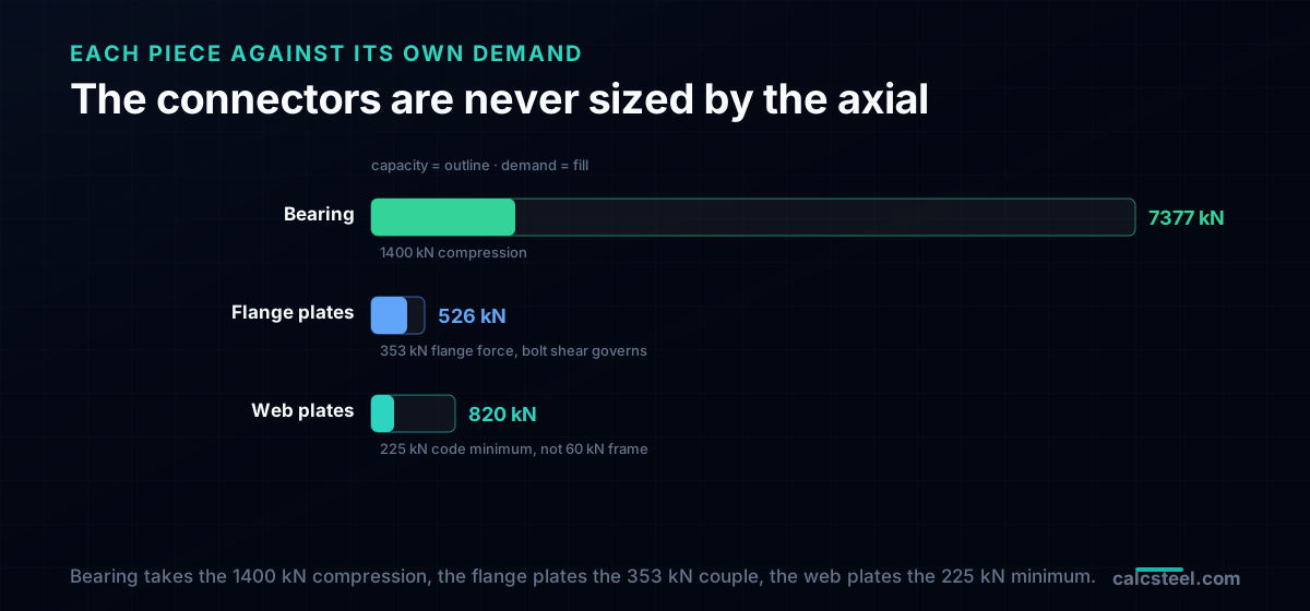
Put the worked column's numbers in. The section is a heavy H, 360 mm deep with 300 mm flanges, a gross area of 15,840 mm.sq in Fy = 345 MPa steel. Milled over its full area, its bearing strength is phi Rn = 0.75 x 1.8 x 345 x 15,840, which is 7,377 kN. The factored compression it has to pass is 1,400 kN. The bearing clears it 5.3 times over. The plates and bolts are asked to carry none of the 1,400 kN in the bearing case; their whole job is to hold the two shafts in line so the milled faces stay in contact and to be there for the forces bearing cannot take, which are tension, shear and moment. This is the single fact that turns a column splice from a large problem into a modest one: the force you were staring at has a path that does not need you.
The force you did not design for: the code minimum
Here is where a column splice surprises people. Take the compression away through bearing, take a case where the wind is light so the moment and the net tension are small, and the analysis says the connectors have almost nothing to carry. The code disagrees. A splice may not be proportioned for the force the model happens to report at that height, because that force can be small for reasons that will not hold in the real building: a slightly different wind direction, an accidental eccentricity, an erection tolerance, or the frame yielding somewhere and redistributing.
Two rules set the floor. Outside a seismic design, AISC 360 J1.4 asks only that a column splice finished to bear have enough connectors to hold all the parts in place, plus, by its User Note, that the joint resist any real tension the load combinations develop, including the uplift a gravity design never triggers. Note what J1.4 does not say: there is no rule that a column splice develop 50 percent, or any fixed fraction, of the column's strength. That 50 percent figure is real, but it belongs to compression members other than columns, and quoting it as a column minimum is a common and expensive mistake.
Inside a building designed to the AISC Seismic Provisions, AISC 341 names a number, and it applies to every column splice, even a gravity column that carries no lateral load. The splice must cross a shear of Mpc / (as x H), the column's plastic moment over the storey height, the shear that would exist if the column reached its full bending strength. For the worked column that is 810 / 3.6 = 225 kN. The frame analysis at the same splice reports 60 kN of storey shear. The code minimum is 3.75 times larger, and it, not the model, sizes the web plates. A special moment frame tightens it further: its bolted splice takes the sum of the plastic moments at both column ends, 450 kN here, its flange plates must develop half the expected flange yield force, over 1100 kN, and a partial-penetration welded splice is designed for twice its required strength. Design a column splice for the reaction the analysis prints and you underbuild it, because the governing number was never in the analysis.
The worked splice
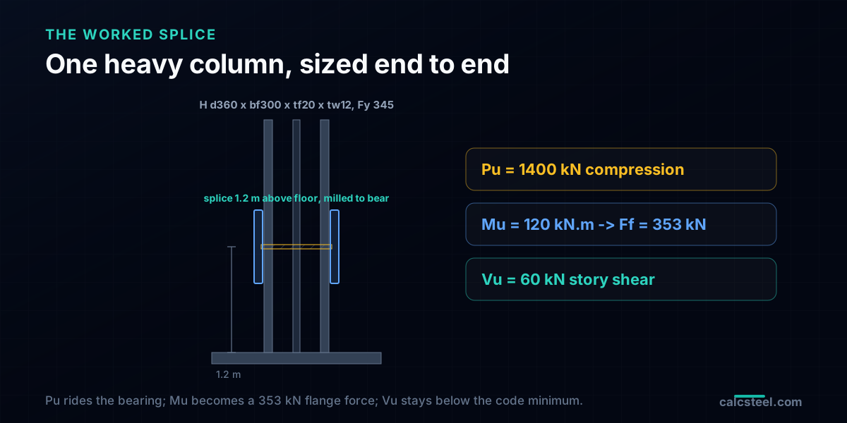
Here is the splice this guide sizes. A heavy H-section column, 360 mm deep, 300 mm flanges 20 mm thick, a 12 mm web, in Fy = 345 MPa steel, the same section top and bottom for now, with the ends milled to bear. The splice sits 1.2 m above the second floor. From the frame analysis, reproducible in the calculator further down, three demands arrive at the splice: a factored compression of Pu = 1,400 kN from 1.2D + 1.6L, a column moment of Mu = 120 kN.m from the 0.9D + 1.0W wind case, and a storey shear of Vu = 60 kN.
Resolve the moment before sizing anything. A moment at the splice is carried as a couple between the flanges, a tension in one flange plate and an equal compression in the other, each equal to the moment divided by the lever arm between the flange centroids. That flange force is Ff = Mu / (d - tf) = 120 / (0.360 - 0.020) = 353 kN. Keep the four numbers in view: 1,400 kN of compression that bearing will take, a 353 kN flange force from the moment, 60 kN of frame shear, and, waiting behind them, the 225 kN code-minimum shear. The design is now a matter of matching each to the piece of steel that carries it. The interaction of that axial and moment on the shaft itself is the combined axial and bending check the column already passed to get here.
Sizing the connectors: what they actually carry
Line each piece of steel up against the force it answers, using bolted plates in Fy = 345, Fu = 450 MPa steel with M20 A325 bolts (grade 8.8 equivalent) in standard holes:
| Piece | Force it carries | Capacity | Utilisation |
|---|---|---|---|
| Milled bearing (full section) | Pu = 1400 kN compression | 7377 kN | 19 percent |
| Flange plates 2 x 300 x 16, 6 M20 a side | Ff = 353 kN (from moment) | 526 kN (bolt shear governs) | 67 percent |
| Web plates 2 x 220 x 10 | 225 kN (code minimum, not the 60 kN frame shear) | 820 kN | 27 percent |
Read the table by column, because it is the argument of the whole guide in three rows. The bearing carries the largest force, 1,400 kN, and sits at 19 percent because milled contact is enormously strong; the plates carry none of it. The flange plates are sized by the 353 kN flange force from the moment, and their governing limit is not the plate but the six M20 bolts a side in shear at 526 kN, so they land at 67 percent. The web plates are sized by 225 kN, the seismic code minimum for every building column, not by the 60 kN of shear the frame reports, which would have left them at 7 percent and dangerously light. Every bolt-level check behind those capacities, plate yield and rupture, bolt shear, bolt bearing and tear-out, follows the same rules as any other bolted connection. What is different about a splice is only which demand you feed them, and on a column that demand is the moment couple and the code floor, never the axial.
When the columns are not the same size
The worked splice used one section top and bottom to keep the forces clean, but the reason a splice exists is usually that the upper column is lighter than the lower one. Two things change when the sections step. First, the ends no longer meet flat, so a fill plate (a division plate) packs the difference in flange thickness and, if the depths differ, a horizontal division plate across the joint receives the smaller upper section and spreads its bearing onto the larger lower one. Second, the bearing area is now the contact area of the smaller section, not the larger, because compression can only cross where steel actually meets steel: size the bearing on the upper column, and check the division plate in bending and the lower column's web for the concentrated load, the same web-crippling and yielding family a beam sees under a concentrated load.
The connectors change too. Bolts that pass through a fill plate thicker than about 6 mm either need the fill developed (extra bolts, or the fill extended and bolted) or a reduction on their shear strength, because a thick loose packer lets the plies slip before the bolts bear evenly. None of this touches the location logic or the four forces; it is the same splice, with an extra plate to carry the compression across a step and a rule to keep the bolts honest through the packing.
Welded or bolted, and the penalty on partial welds
A splice can be bolted with plates or welded with groove welds, and the choice is mostly about the shop and the site rather than the strength. Bolted splices raise fast: the plates are shop-welded or bolted to one shaft, the erector lands the upper column and runs the field bolts, and the joint carries load as soon as it is snugged and tightened. Welded splices, using complete-joint-penetration (CJP) groove welds, develop the full section and leave a clean line, but they need field welding, access all round, and inspection of every weld, which is slower and weather-dependent.
Partial-joint-penetration (PJP) groove welds are the tempting middle: cheaper than a CJP, no plates. They carry compression in bearing well, but they are weak and brittle in tension across the throat, and that is exactly the demand a splice must be trusted with. This is why the seismic provisions double the required strength of a PJP-welded column splice: it must be designed for twice the force a bolted or CJP splice at the same place would be, a penalty that usually erases the saving and pushes the choice back to bolted plates or a full-penetration weld. The general trade between developing a joint fully and detailing it for a chosen force is the same one behind moment versus shear connections elsewhere in the frame.
Try it: get the demand your splice must cross
The splice check begins with the forces at the splice, and those come from the frame, not from the column schedule. Set up your own frame below: the bay, the storey height, the gravity load and the lateral load. Read the column axial, the column moment at the splice height and the storey shear, and those three numbers are the compression that goes to bearing, the moment that becomes your flange force through M / (d - tf), and the shear the web plates carry. Then compare that shear against the code minimum, the sum of the column plastic moments over the clear height, and size the web plates for whichever is larger. Change the wind and watch the moment and the shear move while the axial barely does, which is the whole reason the connectors, not the compression, decide the splice.
Diagrams plotted on the deformed-free frame geometry. N, V, M recovered from the element end-forces of the direct-stiffness solve (12 elements / member). Moment drawn offset to each member's centreline.
First-order STRENGTH screening at the governing section of the NBR 8800 (BR) ULS envelope (governing CB2): N,d = 73.9 kN, M,d = 109 kN·m. Member buckling and lateral-torsional buckling are NOT included — see the stability flags below and run the full verification in the 3D editor. Click a card to make that resistance code govern the ranking.
ULS load combinations — NBR 8800 (BR)
G + W superposed · 3 combinations| Combination | Factors | Utilization |
|---|---|---|
| CB1 | 1.4 G | 69% |
| CB2governs | 1.4 G + 1.4 W | 76% |
| CB3 | 1 G + 1.4 W | 57% |
Combinations generated by the CalcSteel combinations engine (the same v4 engine the 3D editor uses, 6 codes). Gravity is treated as a single permanent action G; the wind action W is the eaves load. Each combination's γ factors are applied by superposition to the isolated gravity and wind solves, then every section is screened — the worst point of the worst combination governs.
Stability screening (buckling caveats)
not in the strength checkScreening indicators only — assumed sway effective length (K = 1.5) and the full member length as the unbraced length (no intermediate purlin/girt restraint). The strength check above deliberately excludes these; the real member verification (effective lengths from the alignment chart / notional loads, χ and Cb reduction factors, purlin bracing) runs in the 3D editor.
Lightest sections that pass (NBR)
screened 974 profiles| Profile | Mass | Frame steel | Utilization | |
|---|---|---|---|---|
| VS 400x32 | 31.9 kg/m | 723 kg | 82% | |
| VS 350x33 | 33.2 kg/m | 752 kg | 86% | |
| VS 400x34 | 34.4 kg/m | 779 kg | 75% | |
| VS 350x35 | 35.1 kg/m | 795 kg | 80% | |
| VS 400x35 | 35.1 kg/m | 795 kg | 73% |
Five ways a column splice goes wrong
The failures repeat, and every one is a case of sizing the splice for the wrong force or putting it in the wrong place:
1. Sizing the plates for the axial. Passing the full column compression through the plates and bolts when the ends are milled to bear, so the splice is enormously overbuilt for the one force that had a path around it, and often still underchecked for tension.
2. Forgetting the uplift combination. Designing only for gravity, which compresses, and never running 0.9D + 1.0W, so the net tension a tall column sees under overturning finds a splice with no tension path.
3. Using the analysis shear as the demand. Sizing the web plates for the storey shear the model prints and skipping the code minimum, which in a seismic frame is several times larger and is the number that governs.
4. A bare PJP weld in tension. Choosing a partial-penetration groove weld to save money and ignoring both its brittleness across the throat and the doubling the seismic provisions impose on it.
5. Splicing at the floor. Placing the cut down at the beam-to-column connection, in the congested, high-moment region the code tells you to avoid, instead of up in the clear length near the inflection point.
Key takeaways
- A column splice is located about 1.2 m (4 ft) above the finished floor: above the beam connection, on a working platform, and near the inflection point where the moment is low. Low, not zero, and never at the force minimum.
- Compression on a milled column crosses by direct bearing (Rn = 1.8 Fy Apb): on the worked H-section that clears the 1400 kN of factored compression 5.3 times, so the connectors carry almost none of it.
- The connectors carry tension, shear and moment. The 120 kN.m moment becomes a 353 kN flange force through Ff = M/(d - tf), and that sizes the flange plates, at 67 percent on two 300 x 16 plates with six M20 bolts a side.
- The code sets a minimum the analysis does not: AISC 341 asks every column splice for a shear of the column plastic moment over the storey height, here 225 kN, 3.75 times the 60 kN the frame reports, so the web plates are sized by the code.
- A PJP-welded splice is designed for twice its required strength under the seismic provisions, and a stepped splice needs a fill or division plate with the bearing limited to the smaller section.
Sources
- 1.AISC 360-22, Specification for Structural Steel Buildings (Section J1.4 splices in compression members; Section J7 bearing strength)
- 2.AISC 341-22, Seismic Provisions for Structural Steel Buildings (column splice location and required strength; partial-joint-penetration penalty)
- 3.AISC Steel Construction Manual, Part 14, Design of Splices; Part 7 bolt shear (Table 7-1)
- 4.Salmon, Johnson and Malhas, Steel Structures: Design and Behavior (compression members and connections)
- 5.EN 1993-1-8, Eurocode 3, Design of joints (splices and bearing-type connections)
Try CalcSteel for free
Model, analyze and design steel structures in your browser. No install, no signup.
Open the 3D editor