Bolt Bearing and Tear-Out: Edge Distance, Spacing and the Plate That Fails First
Bearing and tear-out are limit states of the plate, not the bolt. This guide shows exactly how edge distance and spacing set the clear distance Lc, why the end bolt is usually the first to go, and how to read the one AISC equation that governs both, with every number checked against the CalcSteel connection engine.
Key takeaways
- Bearing and tear-out are plate limit states, not bolt limit states. AISC 360 folds both into a single check per bolt: φRn = φ × min(1.2 Lc t Fu, 2.4 d t Fu), with φ = 0.75.
- Bearing (2.4 d t Fu) does not care where the bolt sits. Tear-out (1.2 Lc t Fu) depends on the clear distance Lc, so it is set by edge distance for the end bolt and by spacing for interior bolts.
- The crossover is Lc = 2d: below it tear-out governs, above it bearing governs. The end bolt has the smallest Lc, so it is almost always the plate that fails first.
- In the worked M20 joint on a 10 mm Fu 400 plate, the end bolt carries only 86.4 kN in tear-out against 144 kN in bearing. Opening the edge distance from 35 to 51 mm recovers the full 144 kN, with no extra steel.
- The thinnest, lowest Fu ply governs bearing, and this check is separate from bolt shear, block shear and net section rupture. You size the connection for whichever number is smallest.
Which part of a bolted joint actually fails first?
Ask a student to design a bolted connection and the first instinct is almost always to check the bolts. Are they strong enough in shear? That is a fair question, but it is rarely the one that decides the joint. In a huge share of real splices and gusset plates, the bolt is the strongest link in the chain. The part that yields, ovalises and eventually tears is the steel plate around the hole, and it fails in one of two closely related ways: bearing and tear-out.
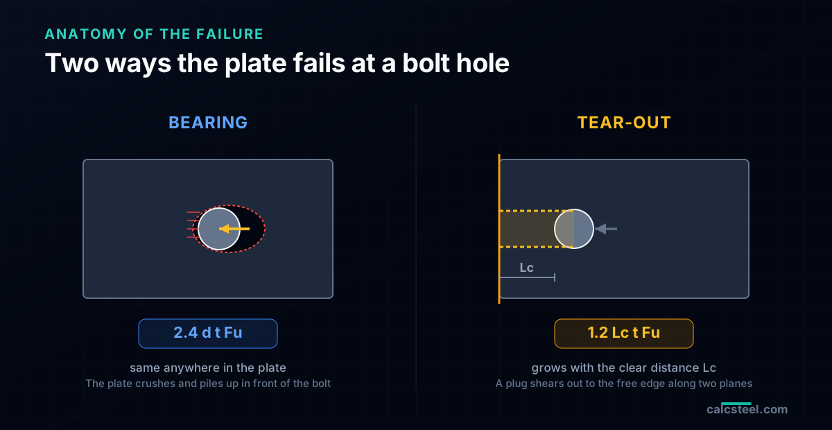
Bearing is the plate crushing and piling up in front of the bolt shank. Tear-out is a plug of plate shearing out between the hole and the free edge, or between one hole and the next. AISC 360 treats them as a single limit state, and the reason this guide exists is that the number which governs is set almost entirely by two dimensions you choose on the detailing sheet: the edge distance and the bolt spacing. Get them wrong and the plate fails at a fraction of the bolt capacity you carefully sized.
Every number here was checked against the CalcSteel connection engine, which implements the AISC and NBR 8800 bearing and tear-out equation exactly, and cross checked against the AISC Steel Construction Manual tables. We wrote it for three readers at once. If you are a student, this is the section your course reduces to one slide. If you are a practising engineer or a freelance calculista, skip to the crossover rule and the worked example, where the edge distance you pick starts costing or saving real capacity. And if you just want the answer, it is this: the end bolt is usually the plate that fails first, and you fix it with millimetres, not more bolts.
This is a deep dive on two limit states. For the full connection, with bolt grades, shear, block shear and slip critical behaviour, start from the bolted connection design guide.
Bearing and tear-out are limit states of the plate
Start with the physical picture, because the equation only makes sense once you can see the failure. A bolt in a loaded plate pushes on the wall of its hole. Two things can give way in the plate, not the bolt.
Bearing: the plate crushes
The bolt shank presses on the hole wall like a punch. If the contact stress is high enough, the plate steel yields locally and the hole ovalises: the material crushes and piles up in front of the bolt. This is bearing. It is a local crushing limit, so it scales with the projected contact area, the bolt diameter d times the plate thickness t, and with the plate ultimate strength Fu. Crucially, it does not care where the bolt sits in the plate. A bolt in the middle of a wide plate has exactly the same bearing capacity as a bolt near the edge.
Tear-out: the plate shears out to the edge
Now put the same bolt close to the end of the plate. Instead of crushing, the block of plate between the hole and the free edge can shear out along two planes, like a plug being pushed out. This is tear-out, sometimes called end tear-out or edge tear-out. It is a shear rupture, and it depends on how much material sits between the hole and the edge in the direction of the force. That distance is the clear distance Lc, and it is the whole story of this article.
Because both failures happen at the same hole under the same force, and because a short edge distance turns bearing into tear-out continuously, AISC 360 does not separate them. It writes one equation with a bearing ceiling and a tear-out term, and you take the smaller. The next section is that equation, term by term.
The one AISC 360 equation, term by term
AISC 360-22 Section J3.10 gives the nominal bearing and tear-out strength at a single bolt hole in a connected element. For standard, oversized and short-slotted holes, with deformation at the bolt hole at service load taken as a design consideration:
Rn = 1.2 Lc t Fu ≤ 2.4 d t Fu
The design strength is φRn with φ = 0.75 for LRFD, or Rn / Omega with Omega = 2.00 for ASD. Read the two terms as what they are:
- 2.4 d t Fu is the bearing ceiling. It is the crushing capacity, and the ≤ means it is an upper bound the tear-out term can never exceed. It has no Lc in it, so it is the same for every bolt in the group.
- 1.2 Lc t Fu is the tear-out term. Here Lc is the clear distance in the direction of the force, from the edge of the hole to the edge of the material or to the edge of the adjacent hole. As Lc grows, tear-out rises linearly until it reaches the bearing ceiling and is capped.
The symbols, once, in SI units:
- d, nominal bolt diameter (for example 20 mm for an M20).
- t, thickness of the connected plate. If the bolt bears on more than one ply in the same direction, you sum the thicknesses of the plies that share that bearing.
- Fu, ultimate tensile strength of the plate, not the bolt. For an A36 or a 250 MPa yield plate, Fu is about 400 MPa (58 ksi).
- Lc, clear distance, computed from edge distance or spacing as the next two sections show.
This is exactly what the CalcSteel connection engine evaluates for every bolt, for AISC and NBR 8800 with φ = 0.75, and with the Eurocode 3 form (k1 alpha_b fu d t divided by gamma_M2) when you switch the code. Same physics, different coefficients. NBR 8800 uses the identical 1.2 and 2.4 factors, which is why a Brazilian calculista and an American engineer land on the same kilonewtons here.
The deformation switch that changes every number
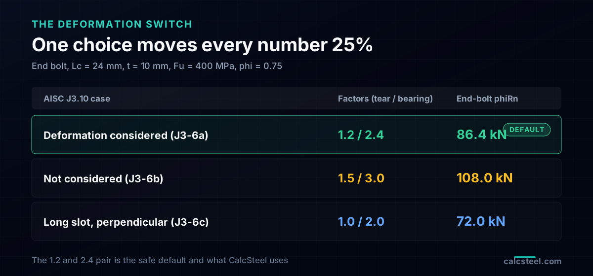
Before touching geometry, there is a coefficient choice that quietly moves every result by 25 percent, and most people never notice they made it. AISC J3.10 gives two pairs of factors, depending on whether hole elongation at service load matters to you:
- Deformation is a design consideration (Equation J3-6a): Rn = 1.2 Lc t Fu ≤ 2.4 d t Fu. This limits hole elongation to about 6.35 mm (0.25 in) at service load. It is the default, and the honest choice for almost all building connections.
- Deformation is not a design consideration (Equation J3-6b): Rn = 1.5 Lc t Fu ≤ 3.0 d t Fu. You are allowed the higher number only when you genuinely do not care how much the hole ovalises, which is rare.
- Long-slotted holes perpendicular to the force (Equation J3-6c): Rn = 1.0 Lc t Fu ≤ 2.0 d t Fu.
To see what the switch is worth, take the end bolt of the worked example below, with Lc = 24 mm on a 10 mm plate at Fu = 400 MPa:
- Deformation considered: φRn = 0.75 × 1.2 × 24 × 10 × 400 / 1000 = 86.4 kN.
- Deformation not considered: φRn = 0.75 × 1.5 × 24 × 10 × 400 / 1000 = 108.0 kN.
- Long-slotted perpendicular: φRn = 0.75 × 1.0 × 24 × 10 × 400 / 1000 = 72.0 kN.
Same bolt, same plate, three different capacities from 72 to 108 kN. The 1.2 and 2.4 pair is the safe default, and it is what the rest of this article and the CalcSteel engine use. If you see a capacity that looks 25 percent generous, check which factor pair produced it.
Edge distance sets the clear distance for the end bolt
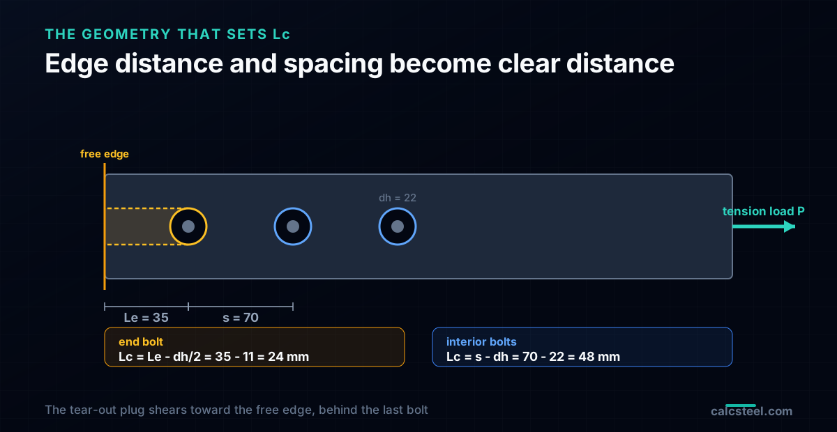
For the bolt nearest a free edge in the line of the force, the material that can tear out is the strip between the hole and that edge. So its clear distance is the edge distance minus half the hole:
Lc = Le − dh / 2
where Le is the edge distance measured to the bolt centre, and dh is the hole diameter. For an M20 in a standard hole, dh = 22 mm (AISC Table J3.3M). If you detail an edge distance of Le = 35 mm, then Lc = 35 − 11 = 24 mm. The single most common mistake in this whole subject is to put Le straight into the tear-out equation and forget the − dh / 2. That one slip overstates the end-bolt capacity by the shear area of half a hole.
How edge distance moves the end bolt
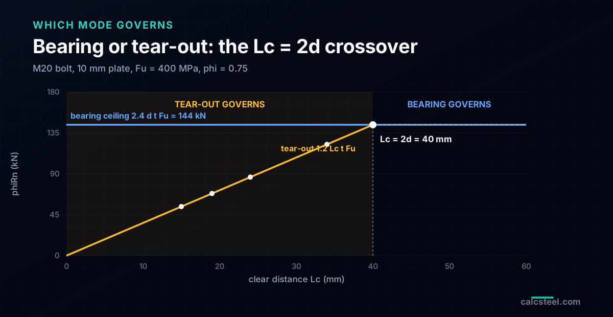
Hold the plate at 10 mm and Fu = 400 MPa and sweep the edge distance. Tear-out climbs in a straight line, and once Lc reaches 2d it is capped by the 144 kN bearing ceiling:
- Le = 26 mm (near the AISC minimum for M20): Lc = 15 mm, φRn = 54.0 kN.
- Le = 30 mm: Lc = 19 mm, φRn = 68.4 kN.
- Le = 35 mm: Lc = 24 mm, φRn = 86.4 kN.
- Le = 45 mm: Lc = 34 mm, φRn = 122.4 kN.
- Le = 51 mm: Lc = 40 mm = 2d, φRn = 144.0 kN, now equal to bearing.
Every one of those numbers is a straight application of 0.75 × 1.2 x Lc x 10 × 400. The lesson is that a few millimetres of edge distance buy a lot of capacity, right up to the point where bearing takes over and more edge distance buys nothing.
Minimum edge distance
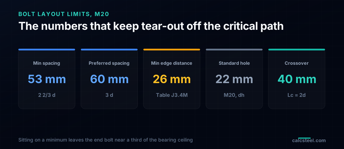
AISC Table J3.4M sets the minimum edge distance so the plate is not detailed into tear-out failure by default. For a 20 mm bolt it is 26 mm. That minimum is a floor for fabrication tolerance, not a target: as the sweep shows, sitting on the minimum leaves the end bolt at roughly a third of the bearing ceiling.
Spacing sets the clear distance for interior bolts
An interior bolt does not tear toward a free edge. It tears toward the previous hole, so its clear distance is the centre-to-centre spacing minus one full hole:
Lc = s − dh
Note the full dh here, not half: the material between two holes is bounded by two hole walls, one from each bolt. For s = 70 mm and dh = 22 mm, Lc = 48 mm. For the preferred spacing of s = 3d = 60 mm, Lc = 38 mm and φRn = 0.75 × 1.2 × 38 × 10 × 400 / 1000 = 136.8 kN. Interior bolts almost always beat end bolts on tear-out, simply because s is larger than Le on any sensible layout.
Minimum, preferred and maximum spacing
AISC J3.3 sets the centre-to-centre spacing rules, and they exist precisely to keep tear-out from governing:
- Minimum spacing: 2 2/3 d, with 3d preferred. For M20 that is 53.3 mm minimum, 60 mm preferred.
- Minimum edge distance: from Table J3.4M, 26 mm for M20, as covered above.
- Maximum spacing and edge distance: to keep plies in contact and exclude moisture, spacing is capped near 24t or 305 mm for painted members, and edge distance at 12t but not more than 150 mm.
These are the same detailing gauges you meet again in column base plate design, where anchor rods replace through bolts but the spacing and edge-distance logic is identical, and the CalcSteel base plate module runs the same bearing check on the plate against the rod.
Bearing or tear-out: the Lc = 2d crossover
Now the payoff. Bearing is a flat ceiling at 2.4 d t Fu. Tear-out is a line, 1.2 Lc t Fu, rising with Lc. Set them equal and the tear-out line meets the bearing ceiling exactly when:
1.2 Lc = 2.4 d, that is Lc = 2d
That single fact tells you which mode governs at any bolt without a calculator:
- If Lc < 2d, the plate tears out. Tear-out governs, and capacity is proportional to Lc.
- If Lc ≥ 2d, the plate crushes first. Bearing governs, and capacity is flat at 2.4 d t Fu no matter how much more edge or spacing you add.
Translate the crossover back into the dimensions you actually detail, for an M20 with dh = 22 mm and 2d = 40 mm:
- End bolt: Lc = Le − dh/2 = 2d needs Le = 2d + dh/2 = 40 + 11 = 51 mm. Below 51 mm of edge distance, the end bolt tears out.
- Interior bolt: Lc = s − dh = 2d needs s = 2d + dh = 40 + 22 = 62 mm. Below 62 mm of spacing, interior bolts tear out.
Since a normal edge distance (35 to 40 mm) is well under 51 mm while a normal spacing (60 to 70 mm) is near or above 62 mm, the end bolt is almost always the one in tear-out while the interior bolts have already reached bearing. That is the structural reason the end bolt is the plate that fails first.
Worked example: three M20 bolts, and the bolt that governs
Put it together on a real detail. A flat tension plate is lap spliced with a single line of three M20 A325 bolts. Plate thickness t = 10 mm, plate ultimate strength Fu = 400 MPa, standard holes dh = 22 mm, edge distance Le = 35 mm, spacing s = 70 mm, deformation considered, φ = 0.75.
Step 1: the bearing ceiling, once
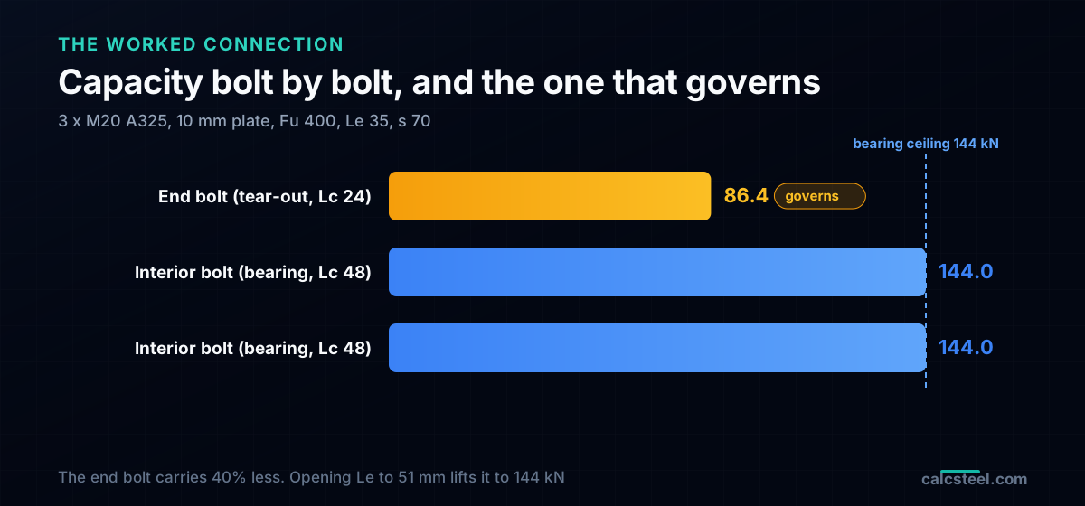
φRn,bearing = 0.75 × 2.4 × 20 × 10 × 400 / 1000 = 144.0 kN per bolt. This is the same for all three bolts.
Step 2: the end bolt in tear-out
Lc = Le − dh/2 = 35 − 11 = 24 mm. φRn,tearout = 0.75 × 1.2 × 24 × 10 × 400 / 1000 = 86.4 kN. Since 24 mm < 2d = 40 mm, tear-out governs. The end bolt is worth min(144.0, 86.4) = 86.4 kN.
Step 3: the two interior bolts
Lc = s − dh = 70 − 22 = 48 mm. φRn,tearout = 0.75 × 1.2 × 48 × 10 × 400 / 1000 = 172.8 kN. Since 48 mm > 40 mm, bearing governs. Each interior bolt is worth min(144.0, 172.8) = 144.0 kN.
Step 4: the connection
Sum the governing value at each bolt: φRn = 86.4 + 144.0 + 144.0 = 374.4 kN. The end bolt alone carries 40 percent less than each of its neighbours. It is the weak link, and it is weak only because its edge distance is short.
Step 5: the fix costs millimetres
Open the edge distance from 35 to 51 mm. Now Lc = 51 − 11 = 40 mm = 2d, the end bolt reaches the bearing ceiling, and its capacity jumps from 86.4 to 144.0 kN, a 67 percent gain for 16 mm of plate. The connection rises to 144.0 × 3 = 432 kN, and no longer has a weak bolt. You did not add a bolt, change the grade or thicken the plate. You moved one edge.
When these three bolts run through this same plate as a tension member, remember that bearing and tear-out are only part of the story: the plate also has to clear gross and net section rupture, and the bolt group has to clear shear and block shear from the full connection guide.
The plate that fails first, and the plate you check
The phrase in the title has two meanings, and both matter on the drawing board.
Which bolt: the end bolt
As the crossover showed, the end bolt has the smallest Lc, so on a normal layout it is the first to tear out. When you scan a connection for the governing bearing and tear-out number, go straight to the bolt nearest the free edge in the line of force. If it passes, the interior bolts almost certainly do too.
Which ply: the thinnest, lowest Fu plate
Bearing and tear-out act on the connected element, and a joint usually has more than one. A thin splice plate against a thick gusset, or a thin angle leg against a heavy column flange, means the check is decided by the thinner, lower Fu ply, because 2.4 d t Fu and 1.2 Lc t Fu both scale with t and Fu. Check the weakest ply in each bearing direction and you have checked the joint. If a single bolt bears on two plies moving the same way, sum their thicknesses for that bolt.
What this check is not
Bearing and tear-out are frequently confused with three other limit states that live on the same connection. Keep them separate:
- Bolt shear cuts the bolt across its shank. It is a property of the bolt, not the plate, and it is checked with Fnv and the bolt area.
- Block shear tears a whole block bounded by a shear plane and a tension plane out of the plate. It involves the bolt group as a set, not one hole.
- Net section rupture pulls the plate apart across the line of holes, a tension failure on the reduced area, covered in gross versus net section.
All four can govern, and the connection is only as strong as the smallest. Bearing and tear-out is the one this guide isolates because it is the one edge distance and spacing control directly.
Five mistakes that quietly overstate the plate
Every one of these turns a safe hand calculation into an unconservative one, and none of them throws an error. They are the reasons a plate rated on paper still ovalises in the shop.
- Using Le as Lc. The tear-out term needs the clear distance, Lc = Le − dh/2 for an end bolt, not the edge distance itself. Forgetting the − dh/2 adds the shear area of half a hole you do not have.
- Using the bolt diameter for the hole. Lc for interior bolts is s − dh, with the hole diameter dh (22 mm for an M20), not the bolt d (20 mm). The 2 mm clearance is real steel you cannot count.
- Applying the 3.0 and 1.5 factors by habit. The deformation-not-considered pair is 25 percent higher and is only valid when hole elongation genuinely does not matter. Default to 1.2 and 2.4.
- Checking only the interior bolts. They are the strong ones. The end bolt, with the smallest Lc, is the plate that fails first, and it is the one to size.
- Reading Fu off the bolt, not the plate. Bearing and tear-out are plate limit states. Use the plate Fu, around 400 MPa for common structural steel, not the bolt tensile strength of 830 MPa or more.
Check it live, and let the engine do every bolt
The fastest way to feel the crossover is to change one number and watch the governing mode flip. The calculator below is the CalcSteel bolt tool, free and with no login for the maths. Set the bolt diameter, plate thickness, edge distance and spacing, and it returns the bearing and tear-out capacity from the same connection engine this article was checked against, alongside bolt shear and pretension.
In a real model the work is larger: every bolt, every ply, every load combination, in both bearing directions. That is what the CalcSteel connection engine automates. It computes Lc from the actual edge and spacing at each bolt, takes the smaller of 1.2 Lc t Fu and 2.4 d t Fu with φ = 0.75 for AISC and NBR 8800, switches to the k1 alpha_b form for Eurocode 3, reports the governing mode and the utilisation, and flags the bolt that fails first. You still bring the judgement: when a joint is eccentric, when bolts see combined shear and tension, or when the layout is unusual, open the detailed output and read every limit state yourself.
Then take the same joint into the full bolted connection design workflow, where bearing and tear-out sit beside shear, block shear and net section, and the connection is sized for whichever governs.
Tightening torque
610 N·m
K±25%: 457–762 N·m
Bolt preload (clamp)
152.4 kN
34,257 lbf
Tensile stress area Aₛ
244.8 mm²
proof 203.2 kN
Proof / yield load
203.2 kN
yield 220.3 kN
How this torque is built — T = K · F · d
Aₛ = 0.7854·(d − 0.9382·P)² = 244.8 mm² (P = 2.5 mm) · engine table Aₛ = 245 mm²
Fₚ (proof) = Aₛ·Sp = 244.8·830 = 203.2 kN
F (preload) = 75%·Fₚ = 152.4 kN = 34,257 lbf
T = K·F·d = 0.20 · 152.4 kN · 20 mm = 610 N·m = 450 lbf·ft
Nut-factor scatter is real — ±25 % on K (Bickford)
Same preload, torque range: 457 N·m … 762 N·mK = 0.20 → 0.150…0.250
Same torque, preload actually installed: 121.9 kN … 203.2 kNa high real K under-tensions the joint
Bolt shear + tension capacity — live from the CalcSteel connection engine
These come straight from engine/connections/boltData — the same NBR 8800:2024 nominal strengths the 3D-editor connection design uses. Torque installs the clamp; this is what the bolt can carry. Single bolt, one shear plane.
Fnv (NBR)
450 MPa
Fnt
750 MPa
φRn — shear
71.6 kN
φRn — tension
119.3 kN
fub = 1000 MPa · Ab = 314 mm² · Aₛ = 245 mm² · φ = 0.65
Structural joints — minimum pretension Tb (NBR 8800 · AISC/RCSC)
Slip-critical and pretensioned connections do not aim for a % of proof load — the code fixes a minimum bolt tension Tb = 0.70·Fu·Aₛ per diameter. Below is that value for the two structural grades at M20, plus the K·Tb·d wrench torque (turn-of-nut and DTI are the code-preferred methods — torque is calibration-only).
ASTM A325 (≈ ISO 8.8)
Tb = 142.2 kN = 31,974 lbf
torque ≈ 569 N·m = 420 lbf·ft
ASTM A490 (≈ ISO 10.9)
Tb = 178.2 kN = 40,063 lbf
torque ≈ 713 N·m = 526 lbf·ft
Bolt torque chart — ISO 10.9 · Plain / as-received (dry) · 75% proof
| Size | Aₛ (mm²) | Preload F | Torque (N·m) | Torque (lbf·ft) |
|---|---|---|---|---|
| 20.1 | 12.5 kN | 15 | 11 | |
| 36.6 | 22.8 kN | 36.5 | 27 | |
| 58 | 36.1 kN | 72.2 | 53 | |
| 84.3 | 52.5 kN | 126 | 93 | |
| 115 | 71.9 kN | 201 | 148 | |
| 157 | 97.5 kN | 312 | 230 | |
| 192 | 119.8 kN | 431 | 318 | |
| 245 | 152.4 kN | 610 | 450 | |
| 303 | 188.9 kN | 831 | 613 | |
| 353 | 219.4 kN | 1,053 | 777 | |
| 459 | 286 kN | 1,544 | 1,139 | |
| 561 | 349 kN | 2,094 | 1,544 | |
| 817 | 508.4 kN | 3,661 | 2,700 |
Nut factors are typical published values — real scatter is ±25 %. For critical joints, calibrate K on your actual fastener/lubricant. Torque values are guidance, not a substitute for a qualified design.
Sources
- 1.AISC 360-22 Specification for Structural Steel Buildings, Section J3.10 (Bearing and Tearout Strength at Bolt Holes)
- 2.AISC Steel Construction Manual, Part 7 (Design of Bolts) bearing and tearout tables
- 3.Salmon, Johnson and Malhas, Steel Structures: Design and Behavior, connections chapters
- 4.ABNT NBR 8800 Design of steel and composite structures, bolt bearing provisions
Try CalcSteel for free
Model, analyze and design steel structures in your browser. No install, no signup.
Open the 3D editor