Moment vs Shear Connections: How the Choice Changes the Whole Frame

The joint you draw at a beam end is not a detailing footnote. It decides where the moment goes, how much steel the beam and columns need, and whether the frame can stand up to wind at all. This guide takes one portal frame, loads it the same way twice, flips the beam-to-column joints from shear to moment, and reads the exact numbers off the CalcSteel FEM engine so you can see the whole frame move.
Key takeaways
- A shear (simple) connection carries vertical shear and lets the beam end rotate freely. A moment (rigid) connection also carries bending, so it ties the beam and column into one continuous member. That single choice redistributes force through the entire frame.
- In the worked 8 m portal under 15 kN/m gravity, shear connections leave the beam simply supported at wL2/8 = 120 kN.m at midspan and the columns carrying pure axial. Making the joints rigid sheds 16.7 kN.m to each beam end, drops midspan to 103.3 kN.m, and forces the columns to carry that same 16.7 kN.m at the top.
- Under a 30 kN lateral push the difference is dramatic. Shear connections on cantilever columns drift 153.6 mm and each column base takes the full (V/2)H = 60 kN.m. The moment frame drifts only 40.9 mm, 3.75 times stiffer, and halves the base moment to 30.7 kN.m.
- Shear connections cannot resist sway on their own. Put them on pinned bases and the frame becomes a four-hinge mechanism: the engine stiffness matrix goes singular and the drift runs away to a meaningless number. That is why simple-connection buildings always need a separate bracing bay, shear wall or core.
- There is no free lunch. Shear connections buy cheap, fast joints and light columns but need a heavier beam and a dedicated lateral system. Moment connections buy an open, self-bracing frame but need heavier columns and expensive, stiff joints. You are trading between the whole beam, the whole column and the whole lateral system, not just picking a detail.
The smallest drawing with the biggest consequences
Ask two engineers to design the same steel frame and hand them the same loads, and you can still get two completely different sets of member sizes. The reason is rarely the load path they assumed or the code they opened. More often it is one decision made almost in passing at the beam ends: is this a shear connection or a moment connection?
It looks like a detailing choice, the kind you settle at the end of a project when the analysis is done. It is the opposite. The connection you assume at each joint is a boundary condition inside the model, and boundary conditions decide where the bending moment lives. Get the assumption right and every downstream number, beam size, column size, base moment, storey drift, is honest. Get it wrong and you can design a beam for half the moment it will actually see, or a frame that cannot carry wind because you quietly assumed a lateral system that was never detailed.
This article is the companion to our decision guide, moment vs shear connections: when to use each. That one tells you which to choose. This one shows you, in numbers from the real CalcSteel FEM engine, exactly what changes in the frame when you flip the switch. We take one portal frame, load it once in gravity and once in wind, solve it with shear joints and then with moment joints, and watch the whole structure respond. Every value below was computed by the shipping engine and cross checked against closed-form statics.
Two families of joint, two jobs
Every beam-to-column connection has to do at least one job: carry the vertical shear from the beam reaction into the column. The question is whether it also carries bending moment.
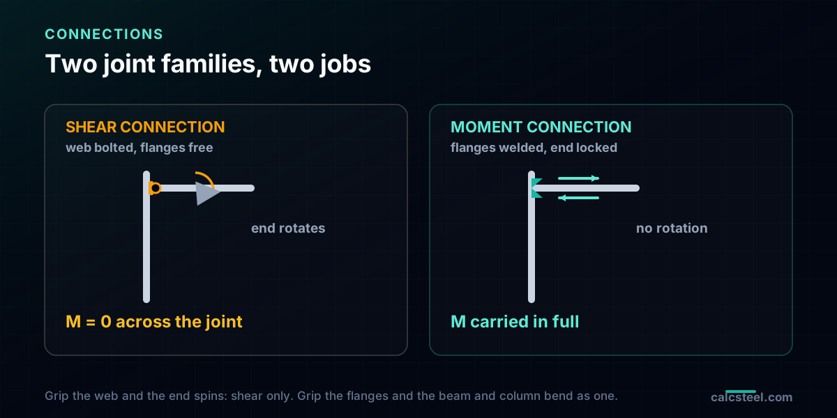
A shear connection, also called a simple or flexible connection, is detailed to carry the reaction and then get out of the way. A single shear tab, a pair of web angles or a fin plate bolts to the beam web only. The flanges, where bending stress lives, are left free. So the beam end can rotate, the joint transmits almost no moment, and the beam behaves as if it were simply supported. In the model it is a pin.
A moment connection, also called a rigid or fully restrained connection, is detailed to carry the reaction and the bending moment. A welded flange-to-column joint, a bolted extended end plate or a haunched connection engages the flanges, so the beam end cannot rotate relative to the column. The beam and column now bend as one continuous frame. In the model it is a rigid joint.
That is the entire difference, and it is enormous. A pin says the moment is zero at the joint. A rigid joint says the beam and column share the moment. Change that one word at every beam end and you have changed the structure the engine solves.
What actually crosses the joint
It helps to picture the internal forces at the very end of the beam, in the last centimetre before the connection. Three things can cross into the column: axial force, shear force and bending moment.
In a shear connection the moment channel is deliberately broken. The bolts through the web can transfer shear happily, but with the flanges free there is no couple to carry bending, so the moment that reaches the column is essentially zero. The connection is strong in shear and soft in rotation. Engineers model this with a moment release, the fixity factor the CalcSteel engine calls rz = 0: the end can spin, and the bending moment it delivers is nil.
In a moment connection the flanges are tied to the column, so a tension-compression couple forms across the beam depth and carries the full bending moment across the joint. Nothing is released. The engine treats it as rz = 1, fully rigid, and the beam-end moment flows straight into the column top. Real joints live on a spectrum between these two ideals, which is the partially restrained case we return to later, but the two endpoints are where the intuition is built.
One frame, one load, solved twice
To see the effect cleanly, we fix everything except the joint. The test structure is a single-bay portal frame:
- Span: L = 8 m, centre to centre of columns
- Eave height: H = 4 m
- Section: one W 360 x 170 (IPE 360 class) for the beam and both columns
- Gravity load: a uniform w = 15 kN/m on the beam
- Lateral load: a single V = 30 kN horizontal push at the windward eave, standing in for wind or notional load
We solve this frame twice. First with shear connections at both beam ends, the beam pinned to the columns. Then with moment connections, the beam rigidly continuous with the columns. Same geometry, same section, same loads. The only thing that moves is the joint, and with it, the whole answer. Column bases stay fixed for the direct comparison, then we test pinned bases at the end to expose why simple frames need bracing.
Gravity with shear connections: the beam carries everything
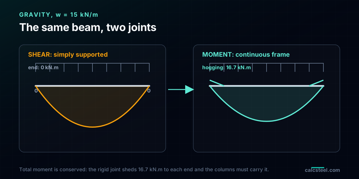
Start with the simple joints. Because each beam end is a pin, the beam is a textbook simply supported member spanning 8 m under 15 kN/m. The midspan moment is the one every student can write from memory:
Mmid = wL2 / 8 = 15 × 82 / 8 = 120 kN.m
The CalcSteel engine confirms it to the third decimal, and it reports zero moment at the beam ends, as a pin demands. The columns feel none of the beam bending. All they receive is the vertical reaction, half the total load each:
Ncolumn = wL / 2 = 15 × 8 / 2 = 60 kN, with a base moment of 0 kN.m.
So the story of the shear frame under gravity is short: the beam does all the bending work and must be sized for the full 120 kN.m, while the columns are pure axial struts. Clean, predictable, and exactly what a simple-connection design promises.
Gravity with moment connections: the frame shares the load
Now weld the flanges. With the beam continuous into the columns, the beam ends can no longer rotate freely, so a hogging moment develops at each joint and the sagging moment at midspan drops. The engine solves the indeterminate frame and reports:
- Beam end (hogging) moment: 16.7 kN.m
- Beam midspan (sagging) moment: 103.3 kN.m, down from 120
- Column top moment: 16.7 kN.m, exactly the beam end moment
- Column base moment: 8.4 kN.m
Two things are worth dwelling on. First, the beam midspan moment fell by about 14 percent, so the beam itself is a little easier to size. That relief is real, and it is exactly the moment that got pushed out to the ends: the total moment at any section is conserved, it is only redistributed. The theoretical bounds bracket the result, the beam-end moment sits between the pinned value of 0 and the fully clamped wL2/12 = 80 kN.m, and midspan between wL2/24 = 40 and wL2/8 = 120; the frame lands wherever the relative stiffness of beam and column puts it.
Second, and this is the catch, the 16.7 kN.m the beam shed did not vanish. It flowed straight into the column top. The columns are no longer axial struts; they are beam-columns that must be checked for combined axial force and bending. Making the beam easier made the columns harder. That is the trade the whole-frame view exposes and a member-by-member habit hides.
The lateral test: who resists the wind
Gravity is only half the story. The connection choice matters even more when the frame is pushed sideways. We apply V = 30 kN horizontally at the windward eave and read the sway and the base moments.
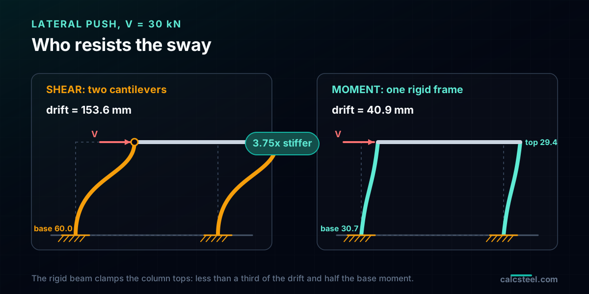
With shear connections and fixed column bases, the pinned beam cannot restrain the column tops, so each column acts as an independent vertical cantilever, tied at the top only by the axial-stiff beam. Each carries half the push, and its base moment is the cantilever value:
Mbase = (V / 2) × H = (30 / 2) × 4 = 60 kN.m per column, with essentially zero moment at the top. The eave drifts 153.6 mm, an alarming H/26.
With moment connections, the rigid beam clamps the column tops, so the frame resists sway as a unit. The engine reports a base moment of 30.7 kN.m, a top moment of 29.4 kN.m, and a drift of just 40.9 mm. The moment frame is 3.75 times stiffer and its columns see half the base moment. The rigid joint did two jobs at once: it cut the drift and it shared the moment between the base and the top instead of dumping it all at the base.
Why simple frames need a lateral system
The fixed-base cantilever above still stood up, just barely, drifting a wild 153.6 mm. Real column bases are rarely that fixed. Detail the same shear-connected frame with pinned bases, the honest assumption for most bolted base plates, and something more serious happens.
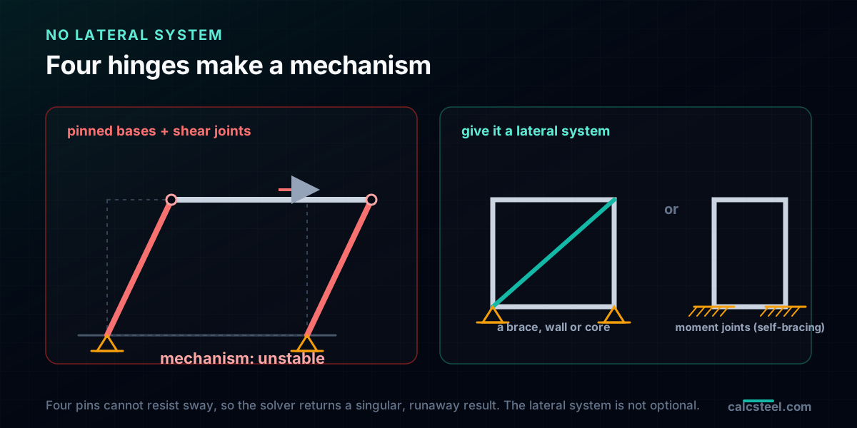
Now the frame has four pins: two at the bases and two at the beam ends. Four pins in a rectangular frame is a mechanism. It has no resistance to sway at all; nudge it sideways and it collapses into a parallelogram. When we hand this model to the CalcSteel engine, the global stiffness matrix goes singular, the solver flags an ill-conditioned system, and the computed drift runs away to a physically meaningless 1015 mm. The number is nonsense on purpose: the structure it describes cannot exist.
This is the mechanical reason simple-connection buildings always carry a separate lateral system. If your beam-to-column joints are shear only, the sway resistance has to come from somewhere else: a braced bay of diagonals, a concrete shear wall, or a service core. The moment frame is the alternative that builds the lateral system into the joints themselves. There is no third option where flexible joints resist sway for free.
The whole-frame trade, member by member
Put the two models side by side and the choice stops being about a single detail. It is a trade across the entire frame.
Choose shear connections and you get: the cheapest, fastest joints on the fabrication floor, a couple of bolts through a tab; and light, axial-only columns under gravity. You pay for it with a heavier beam, sized for the full wL2/8, and with a mandatory separate lateral system that eats a bay or a wall line.
Choose moment connections and you get: a self-bracing frame with open, column-free architecture and no diagonals in the way; and a slightly lighter beam. You pay for it with heavier columns that now carry moment, and with expensive, stiff, carefully detailed joints, welded flanges or thick extended end plates with stiffeners, that take time to fabricate and inspect.
Notice that no single member tells the truth on its own. The moment connection made the beam lighter and the columns heavier. The shear connection made the columns lighter and forced a brace somewhere else in the plan. The only fair comparison is at the level of the whole frame, tonnes of steel plus connection labour plus the cost of the lateral system, which is exactly the view an FEM model gives you and a hand check of one member never will.
What the codes call these joints
The two ideals we modelled, the pure pin and the perfectly rigid joint, are exactly the classifications the codes use, with a middle ground for reality.
AISC 360 (Section B3.4) sorts connections into three classes. A simple connection transmits negligible moment and is idealised as free to rotate, our shear connection. A fully restrained (FR) connection transfers moment with negligible relative rotation, our moment connection. A partially restrained (PR) connection sits between: it carries some moment, but the joint rotation is not negligible and must be accounted for in the analysis.
Eurocode EN 1993-1-8 classifies by rotational stiffness Sj,ini against the beam stiffness EI/Lb. A joint is nominally pinned if it is soft enough to rotate freely, rigid if it is stiff enough to hold the beam clamped (the threshold is higher for unbraced frames than braced ones), and semi-rigid in between. Same three families, a different yardstick.
The honest engineering point is that no real joint is a perfect pin or perfectly rigid. A shear tab has a little rotational stiffness; an end plate has a little flexibility. Most codes let you idealise to the nearest endpoint as long as you detail it to behave that way, and reserve the semi-rigid model for when the middle behaviour actually matters. The CalcSteel engine exposes this directly through the end-release fixity factor, which you can set anywhere from 0 (pin) to 1 (rigid).
Five ways the connection assumption goes wrong
Because the joint is a boundary condition, a wrong assumption is silent: the model runs, the numbers look plausible, and the error only shows up in service or on the shop floor. Watch for these five.
- Modelling a pin where you detailed a moment joint, or the reverse. If the model says pin but the fabricator welds the flanges, the real beam sheds moment to columns you sized for pure axial. If the model says rigid but you bolt a simple tab, the beam sees the full wL2/8 you designed away. The model and the detail must tell the same story.
- Using shear connections and forgetting the lateral system. The most dangerous omission in the list. A frame of simple joints with no brace, wall or core is a mechanism, as the runaway drift above showed. The lateral system is not optional.
- Assuming a bolted moment connection is perfectly rigid. Extended end plates and clip angles are semi-rigid. Treating them as fully rigid underestimates the real drift and can miss a serviceability limit. Check the joint stiffness against the code threshold before you trust the pin-or-rigid idealisation.
- Sizing the beam for the simple-beam moment while modelling it as continuous. Pick one story. If the frame is continuous, design the beam for the redistributed moment and design the columns for the moment they now carry. Do not take the relief at midspan and forget the penalty at the ends and in the columns.
- Forgetting the column became a beam-column. The moment that leaves the beam arrives at the column top. A column that was fine in pure compression can fail the combined axial-plus-bending interaction check once the joint is made rigid.
Try it live: flip the joint and watch the frame
The fastest way to build the intuition is to change one boundary condition and watch every number move. The calculator below is the CalcSteel portal-frame tool, running the same FEM engine this article was checked against, free and with no login for the maths. Set the span, the height, the section and the loads, and read the moments, the base reactions and the sway. Then compare a frame with rigid joints against one with released beam ends and see the redistribution and the drift change in front of you.
In a real project the work is larger: many bays, many storeys, gravity and lateral combinations together, and the connections checked for the forces they actually carry. That is what the full CalcSteel model automates. It solves the frame with your real joint fixities, reports the beam and column moments and the storey drift, and then lets you design each connection, shear tab or moment end plate, for the demand the analysis produced. You still bring the judgement about which joint each location deserves; the engine makes the consequences visible.
When you have chosen, our companion guide on when to use moment vs shear connections walks through the decision case by case, and the steel bracing systems guide covers the lateral system a simple frame needs.
Diagrams plotted on the deformed-free frame geometry. N, V, M recovered from the element end-forces of the direct-stiffness solve (12 elements / member). Moment drawn offset to each member's centreline.
First-order STRENGTH screening at the governing section of the NBR 8800 (BR) ULS envelope (governing CB2): N,d = 73.9 kN, M,d = 109 kN·m. Member buckling and lateral-torsional buckling are NOT included — see the stability flags below and run the full verification in the 3D editor. Click a card to make that resistance code govern the ranking.
ULS load combinations — NBR 8800 (BR)
G + W superposed · 3 combinations| Combination | Factors | Utilization |
|---|---|---|
| CB1 | 1.4 G | 69% |
| CB2governs | 1.4 G + 1.4 W | 76% |
| CB3 | 1 G + 1.4 W | 57% |
Combinations generated by the CalcSteel combinations engine (the same v4 engine the 3D editor uses, 6 codes). Gravity is treated as a single permanent action G; the wind action W is the eaves load. Each combination's γ factors are applied by superposition to the isolated gravity and wind solves, then every section is screened — the worst point of the worst combination governs.
Stability screening (buckling caveats)
not in the strength checkScreening indicators only — assumed sway effective length (K = 1.5) and the full member length as the unbraced length (no intermediate purlin/girt restraint). The strength check above deliberately excludes these; the real member verification (effective lengths from the alignment chart / notional loads, χ and Cb reduction factors, purlin bracing) runs in the 3D editor.
Lightest sections that pass (NBR)
screened 974 profiles| Profile | Mass | Frame steel | Utilization | |
|---|---|---|---|---|
| VS 400x32 | 31.9 kg/m | 723 kg | 82% | |
| VS 350x33 | 33.2 kg/m | 752 kg | 86% | |
| VS 400x34 | 34.4 kg/m | 779 kg | 75% | |
| VS 350x35 | 35.1 kg/m | 795 kg | 80% | |
| VS 400x35 | 35.1 kg/m | 795 kg | 73% |
Sources
- 1.AISC 360-22 Specification for Structural Steel Buildings, Section B3.4 (Design of Connections) and Chapter J
- 2.AISC Steel Construction Manual, Part 10 (Design of Simple Shear Connections) and Parts 11-12 (Design of Partially and Fully Restrained Moment Connections)
- 3.EN 1993-1-8 Eurocode 3: Design of steel structures, Part 1-8: Design of joints, Section 5.2 (Classification of joints by stiffness)
- 4.ABNT NBR 8800 Projeto de estruturas de aco e de estruturas mistas de aco e concreto de edificios, connections and frame stability
- 5.Monforton, G. R. and Wu, T. S., Matrix Analysis of Semi-Rigidly Connected Frames, Journal of the Structural Division, ASCE, 1963
Try CalcSteel for free
Model, analyze and design steel structures in your browser. No install, no signup.
Open the 3D editor