Connection for a 200 kN Beam Reaction: Bolts, Plate and Weld All Checked
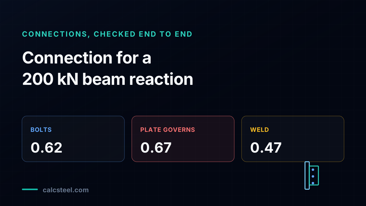
A connection for a 200 kN beam reaction reads like a bolt count: divide the load by the shear capacity of one bolt, round up, done. This deep-dive designs one real single-plate (fin) connection for a 200 kN factored reaction, taken from a live CalcSteel beam run, and checks every AISC 360 limit state across the bolts, the plate and the weld. Two twists the count never sees. First, a shear tab is eccentric, so the bolts that read 0.57 on a concentric count actually work at 0.62. Second, the limit state that governs is not the bolts at all, it is the plate, ruptured on its net section at 0.67, with block shear at 0.63 right behind it. The top of the scorecard is a three-way cluster, and none of it is the bolt count you started with. Free, no login, and free for students.
Key takeaways
- A connection for a 200 kN beam reaction is governed by the plate, not the bolts. On this worked single-plate connection the plate net-section shear rupture is the lowest capacity, 297.2 kN, a utilisation of 0.67, while the bolt group carries the reaction with room to spare.
- The bolt count is optimistic twice. A concentric count of four M20 bolts reads 0.57, but a shear tab is eccentric: the reaction acts 50 mm from the weld line, so the critical bolt works at 0.62, not 0.57. And even that is only the third-lowest check, behind two plate limit states the count never opens.
- The plate holds the two lowest capacities. Net shear rupture governs at 297.2 kN (0.67) and block shear rupture is next at 317.4 kN (0.63). The four 22 mm holes remove 88 mm from the 280 mm depth, and net rupture on the tensile strength beats gross yielding on the yield strength once the net area falls below about 85 percent of the gross.
- The weld is sized not to govern. At five eighths of the plate thickness, a 5 mm two-sided fillet reaches 429.4 kN, a utilisation of 0.47. The five-eighths rule is deliberate: it makes the plate yield before the weld, so a conventional single-plate weld carries the reaction without being designed for the eccentricity, and the plate flexure that the eccentricity does cause is a comfortable 0.19.
- The governing limit state moves with the geometry. Thicken the plate from 8 to 10 mm and every plate check climbs clear, handing the governor to the eccentric bolt group at 0.62. The lesson is to run all of them, because the controlling check migrates between the parts and it is rarely the bolt count you did first.
The question that looks like a bolt count, and why it is not
Ask how to design a connection for a 200 kN beam reaction and the fast answer is arithmetic: take the shear capacity of one bolt, divide the 200 kN by it, round up, and you have your bolt count. It feels finished because the bolts are the visible part of the joint, the thing you can count in a photograph. The trouble is that a shear connection is not one component, it is three in series, and a chain in series is only as strong as its weakest link. The reaction runs from the beam web into the bolts, out of the bolts into the plate, and out of the plate through the weld into the column. Any one of those can be the link that fails first, and the bolt count only sees the first one.
This article designs one concrete joint all the way through and lets the numbers settle which link governs. A single-plate (fin) shear connection carrying a 200 kN factored end reaction, taken from a live CalcSteel beam run, with four M20 bolts, an 8 mm S275 plate and a two-sided fillet weld. We run every AISC 360 limit state across the bolts, the plate and the weld, and rank them. Here is the whole point in advance: the bolt count is wrong twice. It reports the bolts at 0.57 when the shear-tab eccentricity actually works them at 0.62, and it never opens the plate, which is where the governing check lives, net-section shear rupture at 0.67. The bolt count is not even a safe read of the bolts, let alone of the connection.
The worked joint: a single plate, 200 kN, bolts and weld
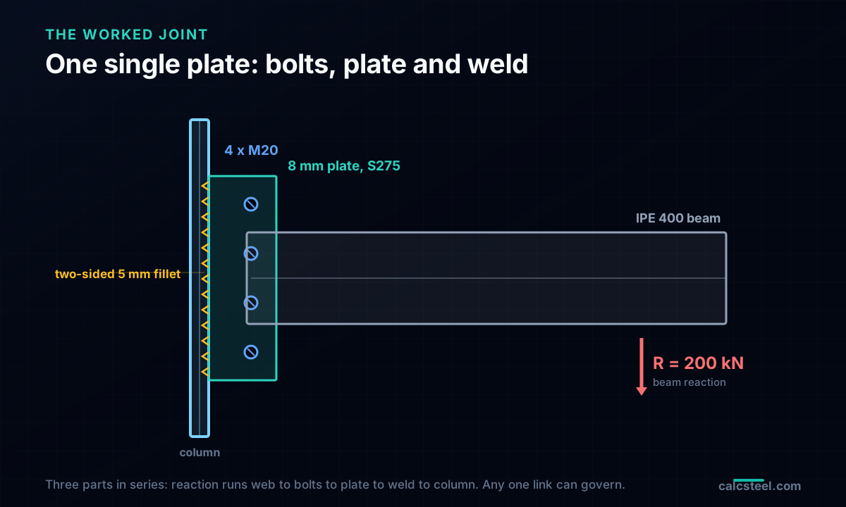
Here is the connection we carry through the article. A beam frames into the flange of a column and delivers a 200 kN vertical reaction. It is a single-plate shear connection, the workhorse of steel framing: one rectangular plate, welded along its vertical edge to the support and bolted through its face to the beam web. It transfers the reaction as shear and lets the beam end rotate, which is what a simple (pinned) connection is meant to do.
- The beam is an IPE 400 in S355 steel, web thickness 8.6 mm, uncoped. Its end reaction is the 200 kN we are connecting.
- The bolts are four M20, Group A (A325 class), in a single vertical line at a 70 mm pitch, with the threads in the shear plane. Standard 22 mm holes, and a 35 mm edge distance top and bottom.
- The plate is 8 mm thick, S275 steel (yield 275 MPa, tensile 430 MPa), 280 mm deep and 90 mm wide, with the bolt line set 50 mm from the weld and 40 mm from the free edge.
- The weld is a two-sided 5 mm fillet, E70 electrode, running the full 280 mm height on each side of the plate.
This is a conventional single-plate configuration in the sense the AISC Manual defines: a single bolt line, the bolt-to-weld distance a = 50 mm under the 89 mm limit, and a plate thin enough (8 mm is under the roughly 11.6 mm ductility cap for M20) that the plate yields before the bolts. That configuration is what lets the code design the weld and the bolt group with the simple rules below. Every number that follows is the AISC 360 design strength, the capital-phi times the nominal, and every one answers the same 200 kN.
Where the 200 kN comes from, checked against statics
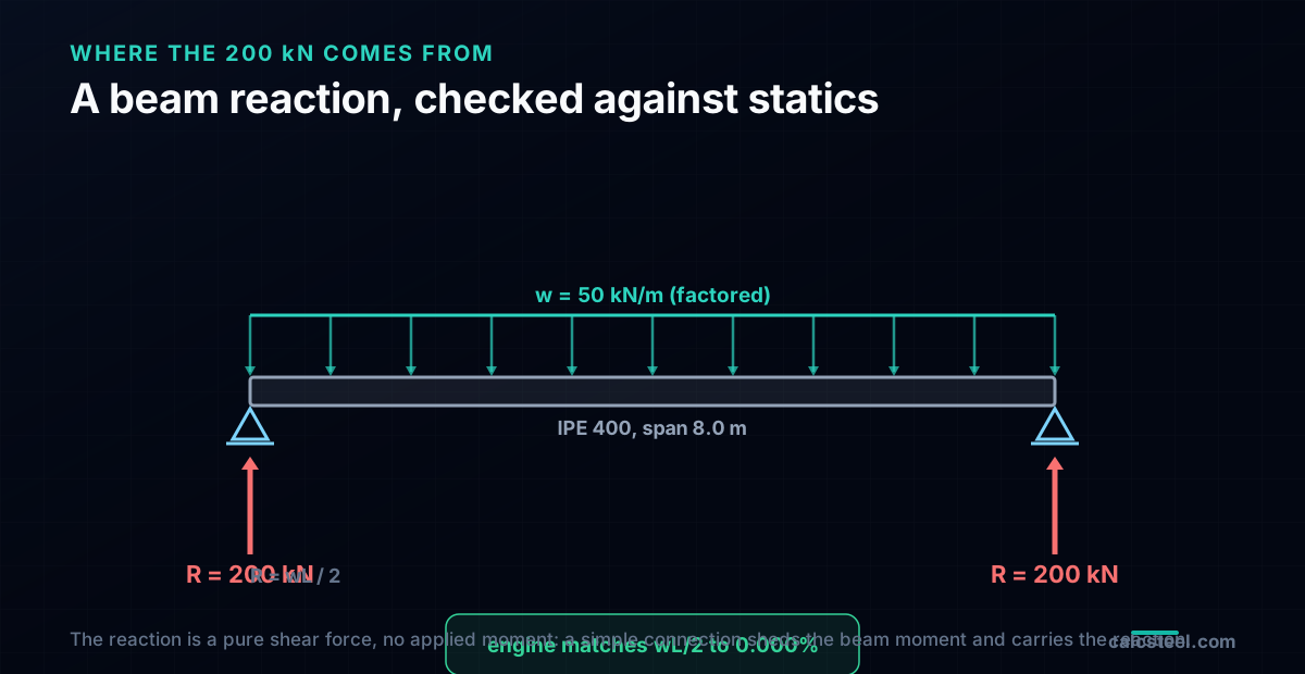
The reaction is not a number we picked, it is one the structure delivers. Drop a simply supported IPE 400, 8.0 m span, under a factored uniform load of 50 kN/m into the CalcSteel finite element engine and read the support reaction. It returns exactly what statics predicts, which is the point of running the control first:
- End reaction from the engine, 200.0 kN, matching the closed-form wL over 2 (50 x 8 / 2 = 200 kN) to 0.000 percent.
That agreement certifies the load path is what we think it is, so the connection we design next is answering the right demand. The 200 kN is now fixed. It does not depend on the plate thickness, the bolt count or the weld size; it is the load the beam hands the connection, and every capacity we compute has to beat it. Notice already that the demand is a single shear force with no applied beam moment: a simple connection is detailed to shed the beam moment, so the joint carries the reaction, not the beam bending. That is why the checks below are shear, bearing and weld limit states.
Size the bolts first, the way everyone does
Start where instinct starts, with the bolts. AISC 360 gives the shear rupture strength of a bolt group as the number of bolts times the nominal shear stress times the bolt area, with a resistance factor of 0.75. For an M20 Group A bolt with the threads in the shear plane, the nominal shear stress is 372 MPa and the nominal area is 314 square millimetres, so one bolt in single shear is worth:
phi x rn = 0.75 x 372 x 314 = 87.7 kN per bolt
Divide the 200 kN reaction by 87.7 and you need 2.3 bolts, so three would carry it and four gives room. Take the four M20 we detailed, and the concentric bolt group design shear is:
phiRn = 4 x 87.7 = 350.6 kN, a utilisation of 200 / 350.6 = 0.57.
At 0.57 the bolts look almost oversized, 43 percent of their capacity unused, and this is the number the bolt-count method hands you. It is also not quite right, and not just because the plate and weld have not been looked at. That 0.57 assumes the reaction passes straight down the bolt line with no eccentricity, and on a shear tab it does not. The next section puts the eccentricity back, and the bolts move.
A shear tab is eccentric: the bolts really work at 0.62
Look at where the reaction actually is. It arrives in the beam web, but the plate does not reach the beam web at the weld line, it reaches it a distance a = 50 mm away, out at the bolt line. So the 200 kN travels down the bolts offset from the weld, and that offset is an eccentricity. The bolt group carries the shear and a moment at the same time, and the conventional single-plate procedure accounts for it with a design eccentricity of eb = a / 2 = 25 mm on the bolts (for standard holes).
Work it with the elastic vector method. The direct shear splits evenly, 200 / 4 = 50 kN down each bolt. The moment M = 200 x 0.025 = 5.0 kN.m spins the group, and the two outer bolts, 105 mm from the centre, pick up the largest horizontal share, about 21.4 kN each. Add the two components on the critical outer bolt as vectors:
R = sqrt(50^2 + 21.4^2) = 54.4 kN on the worst bolt, against the 87.7 kN one bolt can carry.
That is a utilisation of 54.4 / 87.7 = 0.62, not the 0.57 the concentric count reported. The eccentricity, small as it looks, lifts the real bolt demand by nine percent, because it lands entirely on the two end bolts instead of sharing across four. The concentric count was optimistic. The bolts still pass, comfortably, but at 0.62 they are closer to the action than the count ever suggested, and, as the scorecard will show, they are still not the check that governs.
Try it: put your own bolts in
Before we open the plate, size a bolted joint yourself. The free bolt calculator below takes a bolt size, grade and count and returns the group capacity, the same J3 shear path we just used. Put in four M20 bolts, then try three, and watch the utilisation cross from comfortable to tight. It is the bolt half of the connection, live and with no login, and it is the fastest way to feel how much headroom the bolts have before the eccentricity and the plate ever enter the picture.
Tightening torque
610 N·m
K±25%: 457–762 N·m
Bolt preload (clamp)
152.4 kN
34,257 lbf
Tensile stress area Aₛ
244.8 mm²
proof 203.2 kN
Proof / yield load
203.2 kN
yield 220.3 kN
How this torque is built — T = K · F · d
Aₛ = 0.7854·(d − 0.9382·P)² = 244.8 mm² (P = 2.5 mm) · engine table Aₛ = 245 mm²
Fₚ (proof) = Aₛ·Sp = 244.8·830 = 203.2 kN
F (preload) = 75%·Fₚ = 152.4 kN = 34,257 lbf
T = K·F·d = 0.20 · 152.4 kN · 20 mm = 610 N·m = 450 lbf·ft
Nut-factor scatter is real — ±25 % on K (Bickford)
Same preload, torque range: 457 N·m … 762 N·mK = 0.20 → 0.150…0.250
Same torque, preload actually installed: 121.9 kN … 203.2 kNa high real K under-tensions the joint
Bolt shear + tension capacity — live from the CalcSteel connection engine
These come straight from engine/connections/boltData — the same NBR 8800:2024 nominal strengths the 3D-editor connection design uses. Torque installs the clamp; this is what the bolt can carry. Single bolt, one shear plane.
Fnv (NBR)
450 MPa
Fnt
750 MPa
φRn — shear
71.6 kN
φRn — tension
119.3 kN
fub = 1000 MPa · Ab = 314 mm² · Aₛ = 245 mm² · φ = 0.65
Structural joints — minimum pretension Tb (NBR 8800 · AISC/RCSC)
Slip-critical and pretensioned connections do not aim for a % of proof load — the code fixes a minimum bolt tension Tb = 0.70·Fu·Aₛ per diameter. Below is that value for the two structural grades at M20, plus the K·Tb·d wrench torque (turn-of-nut and DTI are the code-preferred methods — torque is calibration-only).
ASTM A325 (≈ ISO 8.8)
Tb = 142.2 kN = 31,974 lbf
torque ≈ 569 N·m = 420 lbf·ft
ASTM A490 (≈ ISO 10.9)
Tb = 178.2 kN = 40,063 lbf
torque ≈ 713 N·m = 526 lbf·ft
Bolt torque chart — ISO 10.9 · Plain / as-received (dry) · 75% proof
| Size | Aₛ (mm²) | Preload F | Torque (N·m) | Torque (lbf·ft) |
|---|---|---|---|---|
| 20.1 | 12.5 kN | 15 | 11 | |
| 36.6 | 22.8 kN | 36.5 | 27 | |
| 58 | 36.1 kN | 72.2 | 53 | |
| 84.3 | 52.5 kN | 126 | 93 | |
| 115 | 71.9 kN | 201 | 148 | |
| 157 | 97.5 kN | 312 | 230 | |
| 192 | 119.8 kN | 431 | 318 | |
| 245 | 152.4 kN | 610 | 450 | |
| 303 | 188.9 kN | 831 | 613 | |
| 353 | 219.4 kN | 1,053 | 777 | |
| 459 | 286 kN | 1,544 | 1,139 | |
| 561 | 349 kN | 2,094 | 1,544 | |
| 817 | 508.4 kN | 3,661 | 2,700 |
Nut factors are typical published values — real scatter is ±25 %. For critical joints, calibrate K on your actual fastener/lubricant. Torque values are guidance, not a substitute for a qualified design.
The full set of checks a shear connection has
A single-plate connection is not one calculation, it is a set of them, spread across the three parts. Here is the list, each an AISC 360 limit state, each answering the same 200 kN:
- Bolts. Bolt shear rupture including the eccentricity (Chapter J3), bolt bearing and tear-out on the plate, and bolt bearing and tear-out on the beam web. Bearing and tear-out are limit states of the connected material at the hole, not of the bolt.
- Plate. Gross-section shear yielding (Section J4.2), net-section shear rupture, block shear rupture (Section J4.3), and plate flexure from the eccentric moment.
- Weld. The two-sided fillet weld joining the plate to the support (Chapter J2).
The design strength of the connection is the smallest of them. There is no averaging and no sharing: the reaction has one load path, and the weakest link on that path is the capacity of the whole joint. The bolt count checks one item on this list. The value of running the rest is that the governing one is almost never the one you would guess, and on this joint it is a plate check that a bolt count never reaches.
The plate governs: net shear rupture at 0.67
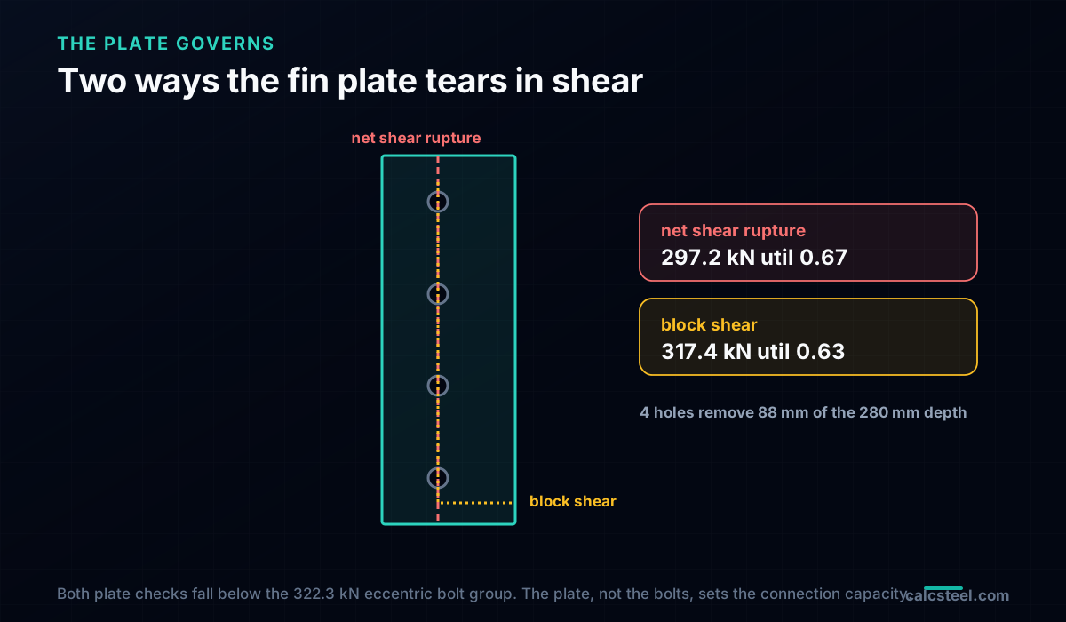
Now open the plate. It is 280 mm deep and 8 mm thick, and the four 22 mm holes punch straight through the middle of it. Two shear limit states compete.
Gross-section shear yielding checks the full 280 mm depth. With a resistance factor of 1.00, the design strength is 0.60 times the yield times the gross area:
phiRn = 1.00 x 0.60 x 275 x (280 x 8) = 369.6 kN, utilisation 0.54.
Net-section shear rupture checks what is left after the holes. Four 22 mm holes remove 88 mm, leaving a net depth of 192 mm, and rupture is governed by the tensile strength with a 0.75 factor:
phiRn = 0.75 x 0.60 x 430 x (192 x 8) = 297.2 kN, utilisation 0.67.
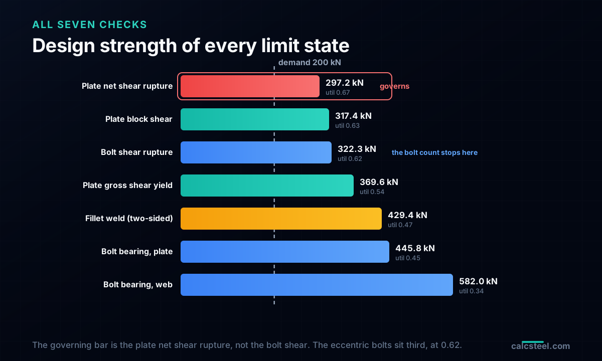
Net rupture wins because the holes have taken enough of the section. Once the net area drops below about 85 percent of the gross, the higher tensile strength on the net area no longer outruns the yield strength on the gross, and the net section governs. Here the net area is only 69 percent of the gross, so rupture governs comfortably. The third plate check, block shear rupture, is the tear-out of an L-shaped block, the bolt line shearing downward while the bottom of the block pulls out in tension. It comes in at 317.4 kN, a utilisation of 0.63. So the plate holds the two lowest numbers on the whole scorecard, 297.2 and 317.4 kN, both below the eccentric bolt demand. The connection is governed by the plate. And the eccentric moment that pushed the bolts up? On the plate it causes only bending, 5.0 kN.m against a 25.9 kN.m capacity, a utilisation of 0.19: real, checked, and nowhere near governing on a plate this deep.
The scorecard: every check, ranked
Put every limit state on one card, sorted by how hard it is working. The governing utilisation is the top row.
| Limit state | Part | phiRn (kN) | Utilisation |
|---|---|---|---|
| Plate net shear rupture | Plate | 297.2 | 0.67 |
| Plate block shear rupture | Plate | 317.4 | 0.63 |
| Bolt shear (with eccentricity) | Bolts | 322.3 | 0.62 |
| Plate gross shear yielding | Plate | 369.6 | 0.54 |
| Fillet weld (two-sided) | Weld | 429.4 | 0.47 |
| Bolt bearing and tear-out, plate | Bolts | 445.8 | 0.45 |
| Bolt bearing and tear-out, web | Bolts | 582.0 | 0.34 |
The shape of the card is the whole lesson. The top three checks are a cluster, 0.67, 0.63 and 0.62, and they belong to three different parts: net shear of the plate, block shear of the plate, and shear of the eccentric bolt group. The connection has no single dominant weakness, it has three checks within five points of each other, and the plate holds the highest two. The bolt-shear utilisation on this row is 0.62, the eccentric value, not the 0.57 a concentric count reports. A count would report 0.57 and call the joint safe at that number, when the true governing utilisation is 0.67, in a part the count never opened. The connection passes, but you only know its real margin, and how little of it there is, once every row is on the card.
The weld, and why it is sized not to govern
The last part is the weld, and it is the one deliberately kept out of the contest. A two-sided 5 mm fillet with an E70 electrode, running the full 280 mm height, has a design strength of:
phiRn = 0.75 x 0.60 x 482 x (0.707 x 5) x (2 x 280) = 429.4 kN, utilisation 0.47.
The 5 mm leg is not a coincidence, it is five eighths of the 8 mm plate, and that ratio is a rule with a purpose. A fillet weld that is at least five eighths of the plate thickness is stronger than the plate it joins, so the plate yields and stretches before the weld can rupture. That ductility is exactly what lets a conventional single-plate connection carry the eccentricity we found on the bolts without designing the weld for a moment: the plate yields and redistributes first. Break the rule with a thin weld on a thick plate and the weld becomes the brittle link, the one place in a ductile joint you least want it. So the weld at 0.47 is not slack, it is a design choice: the plate is the fuse, and the weld is built to outlast it.
Thicken the plate 2 mm and the bolts take over
The governing check is not a fixed property of a 200 kN reaction, it is the balance of the plate against the bolts, and a small change tips it. Keep everything the same and thicken the plate from 8 mm to 10 mm. The plate checks all scale up with the extra material:
- Net shear rupture rises from 297.2 to 371.5 kN, utilisation 0.54.
- Block shear rises from 317.4 to 396.7 kN, utilisation 0.50.
- Gross shear yielding rises from 369.6 to 462.0 kN, utilisation 0.43.
The bolt group does not move, because the bolts do not know how thick the plate is: it stays at the eccentric 0.62. So with a 10 mm plate every plate check clears the bolts, and the governor jumps to the bolt group at 0.62. Two millimetres of plate has handed control from the plate to the bolts. This is the real reason to run everything every time: the limit state that governs migrates with the geometry, from the plate to the bolts to, on a coped beam or a thin web, the web itself. The only way to know which link is weakest is to weigh all of them, not to assume the bolts you counted are the answer, or that the plate always wins.
What the codes ask, on three continents
The worked joint above is AISC 360, but every major code checks a shear connection the same way: the same components in series, the same demand for the smallest capacity to govern, only the symbols change.
- AISC 360 (United States), the path used here: bolt shear and bearing from Chapter J3, plate shear yielding and rupture and block shear from Section J4, welds from Chapter J2, and the single-plate design procedure in Part 10 of the Manual, which is where the bolt eccentricity eb = a/2 comes from.
- Eurocode 3, EN 1993-1-8 (Europe), the connections part, with bolt shear F_v,Rd and bearing F_b,Rd in Table 3.4, block tearing V_eff,Rd in clause 3.10.2, plate resistance in EN 1993-1-1, and fillet welds by the directional or simplified method in clause 4.5. The partial factor gamma_M2 on the rupture checks replaces the AISC 0.75, and the fin-plate joint model carries the same eccentricity.
- ABNT NBR 8800 (Brazil), closely aligned with the AISC form: bolt shear and bearing, shear rupture and block shear of the plate, and fillet welds, each as a resistance that must beat the reaction.
The numbers move a few percent between codes, but the verdict does not. On any of the three, a thin fin plate with a line of holes is checked for net shear and block shear, and on this joint those are the checks that govern. The universal grammar of a shear connection is the series chain and the weakest link, and the bolt count is one clause of it.
Common mistakes and FAQ
"I sized the bolts for the reaction, so the connection is done." This is the mistake the whole article is built to catch. The bolts are one item on the list, and on a single-plate connection they are usually not the one that governs. Here the eccentric bolts are at 0.62 and the plate at 0.67. Check the plate and the weld, not just the bolt count.
"The reaction is concentric, so I ignored the eccentricity." A shear tab is eccentric by geometry: the bolt line sits a distance a from the weld line, and the bolt group carries a moment eb = a/2 times the reaction. On this joint that lifted the bolts from 0.57 to 0.62. It is small here, but it always acts in the wrong direction, and it grows with a.
"Gross shear yielding covers the plate." Only when the net area stays above roughly 85 percent of the gross. With four holes in an 8 mm plate the net area is 69 percent of the gross, so net-section shear rupture governs the plate, not gross yielding. A single line of large holes is exactly where rupture beats yielding.
"Block shear is a tension-member thing." Block shear is a limit state anywhere a group of bolts can tear a block out of the connected material, including the shear plate here and, if the beam were coped, the top of the beam web. On this plate it is the second-lowest capacity, 317.4 kN, closer to governing than the bolts.
"The weld should be as strong as possible." The weld should be strong enough to let the plate yield first, which the five-eighths-of-the-plate rule guarantees, and no thinner. An undersized weld on a single plate turns the ductile fuse into a brittle one. The goal is a ductile joint, not a maximised weld.
From a bolt count to the governing check
The question was how to design a connection for a 200 kN beam reaction, and the honest answer is that the bolt count is the easy part and the wrong place to stop. Feed the joint its real reaction, run every limit state, and the bolt count turns out to be optimistic twice: it reads the bolts at 0.57 when the shear-tab eccentricity works them at 0.62, and it never opens the plate, where the two lowest capacities live, net shear rupture at 297.2 kN and block shear at 317.4 kN. The connection is governed by the plate at a utilisation of 0.67, the top of a three-way cluster, and thicken the plate two millimetres and the answer moves to the bolts.
That is the difference between a bolt count and a connection design. A count reads the reaction and hands you a number of bolts. A design reads the reaction and weighs the bolts, their eccentricity, the plate and the weld together, then hands you the one that governs and the margin you actually have. You can size the bolts yourself in the calculator above, and run the full connection, every limit state, in the CalcSteel editor, free and with no login, and free for students. Put in your own reaction and your own plate, and watch which link is the weakest.
Sources
- 1.AISC 360, Specification for Structural Steel Buildings (Chapter J3 bolts and bearing, Section J4 affected elements in shear and block shear, Chapter J2 welds)
- 2.AISC Steel Construction Manual, Part 10, Design of Simple Shear Connections (single-plate / shear-tab conventional configuration and the bolt-group eccentricity)
- 3.Muir, L.S. and Thornton, W.A. (2011), The Development of a New Design Procedure for Conventional Single-Plate Shear Connections, AISC Engineering Journal, 4th Quarter
- 4.EN 1993-1-8, Eurocode 3: Design of steel structures, Part 1-8, Design of joints (bolt shear and bearing Table 3.4, block tearing 3.10.2, fillet welds 4.5)
- 5.ABNT NBR 8800, Projeto de estruturas de aco e de estruturas mistas de aco e concreto de edificios (ligacoes: parafusos, solda e colapso por rasgamento)
Try CalcSteel for free
Model, analyze and design steel structures in your browser. No install, no signup.
Open the 3D editor