Weld versus Bolt: Cost, Capacity and Inspection Compared on One Joint
Weld or bolt is not a preference, it is a trade among three numbers that rarely point the same way: what the joint can carry, what it costs to make, and what it costs to inspect. This guide takes one ordinary shear connection, a 10 mm plate carrying a 200 kN factored reaction from a real CalcSteel beam run, and designs it twice to AISC 360, once with a bolt group and once with a fillet weld. Same demand, same plate, two fasteners. The capacity comes out close, 263 kN bolted against 307 kN welded, both well over the 200 kN they have to resist. But the way each reaches that number, and what a shop, a field crew and an inspector then do with it, is where the decision actually lives.
Key takeaways
- Same joint, two fasteners. On one 10 mm plate, three M20 A325 bolts give a design shear of 263 kN and a 5 mm E70 fillet weld gives 307 kN, both comfortably over the 200 kN factored reaction. Capacity alone rarely decides between them.
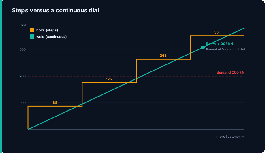
- Bolt capacity adds in discrete steps of 87.7 kN per bolt; weld capacity scales continuously with leg size and length. Here the weld is not sized by demand at all: the 3.2 mm leg the load needs is below the 5 mm minimum fillet, so the code floor governs and you get 307 kN for free.
- The plate limit states, bearing, tear-out, block shear and net-section rupture, belong to the plate, not to the fastener. Switching from bolts to welds does not remove them; you still check the connected element.
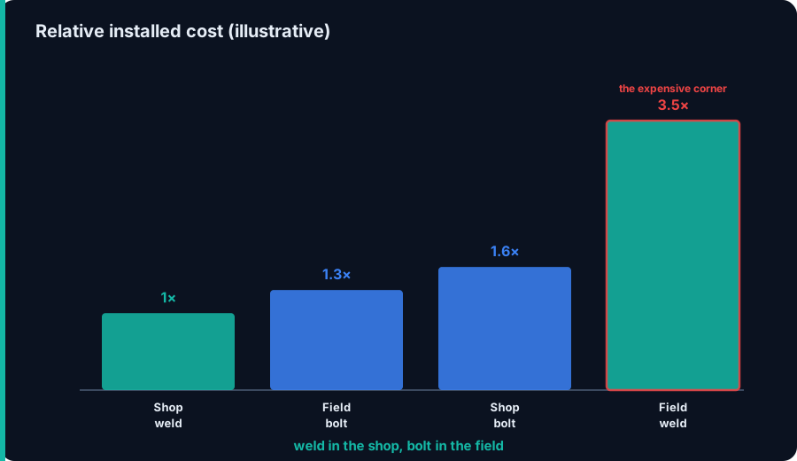
- Cost, not strength, is the usual decider, and it flips with location. Weld in the shop, where a machine and a flat position are cheap, and bolt in the field, where a wrench beats a welder, edge prep and a weather tent.
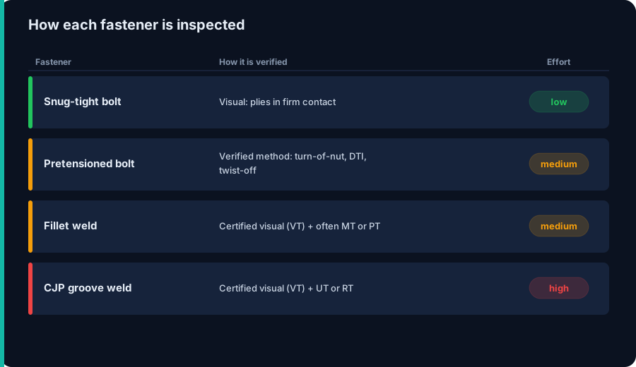
- Inspection is the hidden column. A snug-tight bolt needs only a visual check, a pretensioned bolt needs a verified method, and a fillet weld needs a certified visual plus, often, magnetic particle or ultrasonic testing. The joint that is cheap to weld can be expensive to prove.
One joint, two ways to hold it together
Ask a detailer whether to weld or bolt a connection and you usually get a shop-culture answer: this fabricator welds everything, that erector bolts everything. Both can be right, because the honest answer is not one comparison but three, and they seldom agree. One asks which joint carries more load. One asks which costs less to make. One asks which costs more to prove is sound. A weld can win the first, lose the second and change the third depending on where the work happens.
The cleanest way to see all three at once is to stop arguing in general and design the same joint both ways. So that is what we do here: one plate, one factored reaction, checked once with a bolt group and once with a fillet weld to AISC 360, with the demand taken from a real CalcSteel analysis rather than assumed. Then we line the two up on capacity, on cost and on inspection, and let the numbers say where each belongs.
The worked joint: where the 200 kN comes from
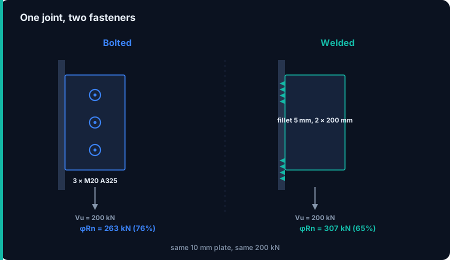
The demand is not invented. A simply supported beam of 8 m span carries a factored uniform load of 50 kN/m, and the CalcSteel engine returns an end reaction of 200 kN, exactly the closed-form wL/2. That reaction is the shear the end connection has to deliver into the support, so Vu = 200 kN is the number both fasteners must beat.
The connecting element is the same in both designs: a 10 mm plate, 200 mm deep, in A36 steel (Fy = 250 MPa, Fu = 400 MPa). In the bolted design the plate is drilled and bolted to the support; in the welded design the same plate is fillet welded to it along its two vertical edges. Keeping the plate identical is what makes the comparison fair: only the fastener changes.
Bolts on the joint
Take M20 A325 bolts (Group A) in single shear, with the threads in the shear plane, the common and conservative assumption. AISC 360 Table J3.2 gives a nominal shear stress Fnv = 372 MPa (54 ksi), and the bolt area is Ab = πd²/4 = 314 mm². The nominal shear per bolt is FnvAb, and with the resistance factor φ = 0.75 the design strength is φRn = 87.7 kN per bolt.
Dividing the demand by that step, 200 / 87.7 = 2.3, so we need 3 bolts, giving a group design shear of 3 × 87.7 = 263 kN, a 76 percent utilization. Bolt shear governs the fastener here: the plate bearing and tear-out ceiling is 144 kN per bolt, well above 87.7 kN, so the bolts fail before the holes do. Those plate checks still have to be made, and they are covered in the bearing and tear-out guide; they are a property of the plate, not of the choice to bolt.
Welds on the joint
Now weld the same plate to the support with a fillet along each of its two vertical edges, a total weld length Lw = 400 mm. With E70XX electrodes (FEXX = 483 MPa, 70 ksi) and the reaction running parallel to the weld axis, the design strength per unit length is φ(0.60 FEXX)(0.707 w), where w is the leg size. Solve that for the demand and the joint needs a leg of only 3.2 mm.
Here is the twist the tables hide: you cannot use it. AISC 360 Table J2.4 sets a minimum fillet of 5 mm for a 10 mm plate, driven by cooling rate, not by demand, so the code floor governs. A 5 mm fillet over 400 mm delivers 307 kN, a 65 percent utilization, and you get that capacity for free. The maximum leg on a 10 mm edge would be 8 mm, and the base metal (plate shear rupture along the welds, 720 kN) never governs. See the fillet weld strength guide for the directional-strength increase when the load runs across the weld instead of along it.
Head to head on capacity
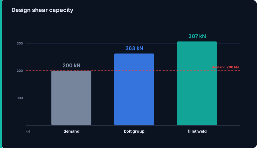
Line the two designs up and the surprise is how little separates them: 263 kN bolted, 307 kN welded, both clearing the 200 kN demand with margin. On this ordinary joint, capacity is not the discriminator. Either fastener works, and picking on strength alone would be picking on noise.
Capacity does start to decide at the extremes. When the demand climbs and the plate is thick, a weld stays compact where a bolt group would need many rows and a longer plate, so the weld wins on geometry. When the material is thin, coated or awkward to reach with an electrode, bolts win. But for the broad middle of everyday shear connections, both land in the same place, which is exactly why the real decision moves to the next two columns.
Capacity in steps versus capacity as a dial
The two fasteners do not build capacity the same way. Bolts come in discrete steps: 87.7 kN, 87.7 × 2, 87.7 × 3, and so on. You cannot buy 2.3 bolts, so you round up to 3 and overshoot the demand. Welds are a continuous dial: leg size and length trade against each other smoothly, so in principle you tune the weld to the load.
In practice the weld has its own floor. The 3.2 mm leg the demand asks for is below the 5 mm minimum fillet, so the dial is pinned at its low end and the joint is oversized by the code, not by you. The lesson runs both ways: on a lightly loaded joint the minimum fillet makes the weld cheap and strong by default, while a heavily loaded joint rewards the weld's smooth scaling, since a bigger leg or a longer run adds capacity without adding a single hole or bolt.
Cost: weld in the shop, bolt in the field
Cost, not strength, is what usually decides, and it is not a single number, it flips with where the work happens. In the shop a weld is cheap: the piece is fixtured flat, the process can be semi or fully automated, and there is no drilling pattern to coordinate between two parts. In the field the balance inverts. A bolt goes in with a wrench in minutes, by a crew that does not need a welding certification, a power source, shielding gas, edge preparation or a tent against wind and rain.
That is the old fabricator rule with a reason behind it: weld in the shop, bolt in the field. Field welding is the expensive corner of the matrix, and it is expensive before a single inspection happens, because of access, position, weather and the certified labor it needs. On the material side the trade is smaller and points the other way: bolts add hardware you buy by the box, welds add consumables and energy, so per joint the fastener hardware is rarely what tips the decision. Labor and location are.
When each one wins
Put the three columns together and a working rule falls out. Reach for bolts when:
- the work is in the field and erection speed matters;
- the joint may be taken apart later (temporary works, phased erection, future extension);
- hot work is a hazard, near galvanizing, coatings, or flammable contents;
- the material is thin or coated and you want to avoid distortion and burn-through.
Reach for welds when:
- the work is in the shop, where welding is cheapest and best controlled;
- the joint must be compact or stiff, a moment connection, a stiffener, a built-up member with no room for a bolt group;
- bolt access is poor or a clean, hole-free appearance is wanted.
Two nuances override the rule. Under fatigue, welds introduce stress concentrations and demand careful detailing, while a properly pretensioned slip-critical bolt can be the calmer choice. And never share one load path between bolts and welds: they have very different stiffness, so they do not draw load in proportion to their strength, and one arrives first. Let each element be all-bolted or all-welded.
Try it yourself
The bolt side of the comparison hides a second decision: how much to pretension. Snug-tight and slip-critical are not the same bolt, and the target pretension sets both the clamping force and the installation method an inspector will later verify. Use the calculator below to see how bolt grade and diameter drive the pretension and the tightening torque, then map that back onto the inspection column above: the more pretension the joint relies on, the more the installation has to be proven.
Tightening torque
610 N·m
K±25%: 457–762 N·m
Bolt preload (clamp)
152.4 kN
34,257 lbf
Tensile stress area Aₛ
244.8 mm²
proof 203.2 kN
Proof / yield load
203.2 kN
yield 220.3 kN
How this torque is built — T = K · F · d
Aₛ = 0.7854·(d − 0.9382·P)² = 244.8 mm² (P = 2.5 mm) · engine table Aₛ = 245 mm²
Fₚ (proof) = Aₛ·Sp = 244.8·830 = 203.2 kN
F (preload) = 75%·Fₚ = 152.4 kN = 34,257 lbf
T = K·F·d = 0.20 · 152.4 kN · 20 mm = 610 N·m = 450 lbf·ft
Nut-factor scatter is real — ±25 % on K (Bickford)
Same preload, torque range: 457 N·m … 762 N·mK = 0.20 → 0.150…0.250
Same torque, preload actually installed: 121.9 kN … 203.2 kNa high real K under-tensions the joint
Bolt shear + tension capacity — live from the CalcSteel connection engine
These come straight from engine/connections/boltData — the same NBR 8800:2024 nominal strengths the 3D-editor connection design uses. Torque installs the clamp; this is what the bolt can carry. Single bolt, one shear plane.
Fnv (NBR)
450 MPa
Fnt
750 MPa
φRn — shear
71.6 kN
φRn — tension
119.3 kN
fub = 1000 MPa · Ab = 314 mm² · Aₛ = 245 mm² · φ = 0.65
Structural joints — minimum pretension Tb (NBR 8800 · AISC/RCSC)
Slip-critical and pretensioned connections do not aim for a % of proof load — the code fixes a minimum bolt tension Tb = 0.70·Fu·Aₛ per diameter. Below is that value for the two structural grades at M20, plus the K·Tb·d wrench torque (turn-of-nut and DTI are the code-preferred methods — torque is calibration-only).
ASTM A325 (≈ ISO 8.8)
Tb = 142.2 kN = 31,974 lbf
torque ≈ 569 N·m = 420 lbf·ft
ASTM A490 (≈ ISO 10.9)
Tb = 178.2 kN = 40,063 lbf
torque ≈ 713 N·m = 526 lbf·ft
Bolt torque chart — ISO 10.9 · Plain / as-received (dry) · 75% proof
| Size | Aₛ (mm²) | Preload F | Torque (N·m) | Torque (lbf·ft) |
|---|---|---|---|---|
| 20.1 | 12.5 kN | 15 | 11 | |
| 36.6 | 22.8 kN | 36.5 | 27 | |
| 58 | 36.1 kN | 72.2 | 53 | |
| 84.3 | 52.5 kN | 126 | 93 | |
| 115 | 71.9 kN | 201 | 148 | |
| 157 | 97.5 kN | 312 | 230 | |
| 192 | 119.8 kN | 431 | 318 | |
| 245 | 152.4 kN | 610 | 450 | |
| 303 | 188.9 kN | 831 | 613 | |
| 353 | 219.4 kN | 1,053 | 777 | |
| 459 | 286 kN | 1,544 | 1,139 | |
| 561 | 349 kN | 2,094 | 1,544 | |
| 817 | 508.4 kN | 3,661 | 2,700 |
Nut factors are typical published values — real scatter is ±25 %. For critical joints, calibrate K on your actual fastener/lubricant. Torque values are guidance, not a substitute for a qualified design.
AISC and Eurocode: the same joint, other symbols
The worked joint is in AISC 360, but the comparison is code-independent, only the notation changes. In EN 1993-1-8 a bolt in shear is Fv,Rd = αv fub A / γM2, the same FnvAb idea with the safety carried by a partial factor instead of φ. A fillet weld uses the directional or the simplified method, with a design shear strength fvw,d = fu / (√3 βw γM2), and the correlation factor βw plays the role of the electrode match.
ABNT NBR 8800 follows the same LRFD-style format as AISC, with resistance factors on bolt shear and on weld metal. The upshot is that the three-column decision, capacity, cost, inspection, is identical across codes; what moves between them is the exact factor and the minimum-fillet table, not the logic of when to weld and when to bolt.
Five ways this goes wrong
- Sizing the weld from demand and forgetting the floor. The load asked for 3.2 mm, but the 5 mm minimum fillet governs. Specifying the smaller leg is a code violation, not an optimization.
- Sharing one load path between bolts and welds. Their stiffnesses differ, so they do not share load by strength; the stiffer path is overloaded first. Make each element all-bolted or all-welded.
- Confusing snug-tight with pretensioned. Pretensioning every bolt wastes money on joints that only need snug; leaving a slip-critical or fatigue joint snug is unsafe. Match the class to the demand.
- Field welding coated or galvanized steel without prep. Zinc and paint make porosity and fumes; the weld that passed on bare plate can fail on a coated one.
- Inspecting the wrong thing. Ordering ultrasonic testing on a fillet weld, or skipping pretension verification on a slip-critical joint, spends the inspection budget where it does not buy safety.
Sources
- 1.AISC 360-22, Specification for Structural Steel Buildings (Chapter J, Design of Connections; Chapter N, Quality Control and Quality Assurance)
- 2.AISC Steel Construction Manual, 16th ed. (Part 7 Bolts, Part 8 Welds, and the economy discussion)
- 3.RCSC, Specification for Structural Joints Using High-Strength Bolts
- 4.AWS D1.1/D1.1M, Structural Welding Code, Steel
- 5.EN 1993-1-8, Eurocode 3, Design of steel structures, Part 1-8: Design of joints
- 6.ABNT NBR 8800, Projeto de estruturas de aco e de estruturas mistas de aco e concreto de edificios
Try CalcSteel for free
Model, analyze and design steel structures in your browser. No install, no signup.
Open the 3D editor