Gross Section versus Net Section: Which One Governs a Bolted Tension Member
A bolted tension member is checked twice at once: gross section yielding along its length and net section rupture at the bolt line. This is gross section versus net section, worked by hand for a plate and an angle on a real steel engine, with the exact rule that tells you which one governs.
Key takeaways
- A bolted tension member has two limit states at once: gross-section yielding (0.90 Fy Ag, ductile, over the whole length) and net-section rupture (0.75 Fu Ae, brittle, at the holes). The design strength is the smaller.
- The net area uses the hole width, not the bolt diameter (M20 gives d_h = 24 mm under AISC), minus every hole on the critical path, plus an s^2/4g credit for each diagonal leg of a staggered path.
- Shear lag reduces the net area to the effective net area Ae = U An, with U = 1 - x-bar/L. A short, one-sided connection can make rupture govern even when the gross area looks generous.
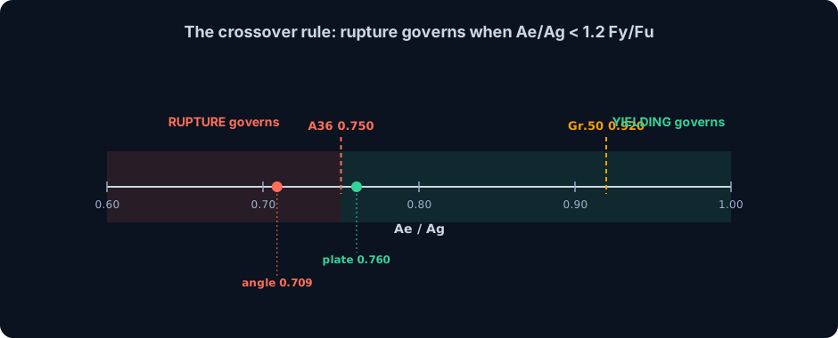
- The crossover rule settles the winner in one line: rupture governs when Ae/Ag < 1.2 Fy/Fu. For A36 that threshold is 0.750, for Grade 50 it is 0.920.
- Higher-strength steel makes net rupture govern more often, because the ductile yielding limit rises faster than the brittle rupture limit as Fy approaches Fu.
Two identical members, two different limit states
Take two tension members cut from the same plate, the same steel, carrying the same pull. Bolt the first through a clean, full cross-section and it will stretch, yield and finally tear only after the whole bar has gone plastic. Drill a line of bolt holes through the second and it can snap at a single cross-section, at a load the first one shrugs off, with almost no warning. Same steel, same force, two completely different failure stories.
That is the entire subject of this article. A bolted tension member is checked against two limit states at once: yielding on the gross section, spread over the full length, and rupture on the net section, concentrated where the bolt holes remove material. The design strength is the smaller of the two, and which one wins is not obvious. It depends on the steel grade, on how many holes you punch, on whether they are staggered, and on how the member is attached. Get the wrong one and you either waste steel or, far worse, miss the mode that actually breaks.
Below we define both limit states, compute them by hand for a plate and an angle to the third decimal, derive the exact crossover rule that tells you which governs before you even open a calculator, and compare how AISC 360, NBR 8800 and Eurocode 3 draw the same line with different safety factors.
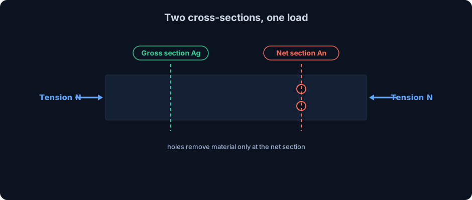
Gross section yielding versus net section rupture
AISC 360 Chapter D states the two checks explicitly. For a member in axial tension the design tensile strength is the lesser of:
- Yielding of the gross section: φtPn = 0.90 · Fy · Ag
- Rupture of the net section: φtPn = 0.75 · Fu · Ae
Three areas appear, and keeping them straight is half the battle:
- Ag, gross area: the full cross-section, holes ignored. This is the area you read off a profile table or the CalcSteel section engine.
- An, net area: the gross area minus the material removed by the bolt holes on the critical failure path, An = Ag − ∑ dh · t.
- Ae, effective net area: the net area reduced further by the shear-lag factor U, Ae = U · An, to account for the fact that not every part of the section is fully engaged at the connection.
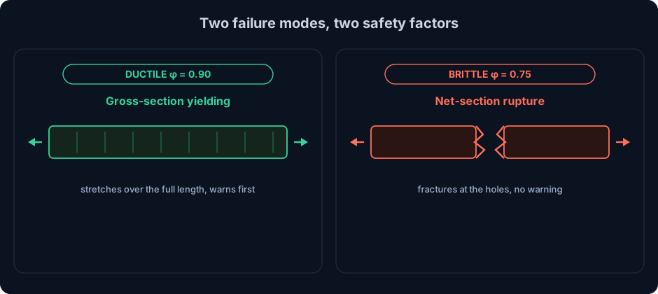
Yielding uses Fy (the yield stress) and the resistance factor 0.90; rupture uses Fu (the ultimate stress) and the lower factor 0.75. Both the stresses and the factors differ, which is exactly why the winner is never a foregone conclusion. The phrase gross section versus net section is shorthand for this competition: FyAg against FuAe, weighted by 0.90 against 0.75.
Why two different resistance factors, 0.90 and 0.75
The gap between 0.90 and 0.75 is not arbitrary bookkeeping, it encodes how the two failures behave. Gross-section yielding is ductile. When the full length of the bar reaches Fy, it stretches visibly, sheds load into neighbouring members, and gives ample warning long before it tears. A member that yields is not a member that has collapsed, so the code treats yielding as a serviceability-flavoured limit with a generous factor of 0.90.
Net-section rupture is brittle. Fracture initiates at the edge of a bolt hole, where stress concentrates, and races across the reduced section with little plastic warning. There is no reserve past it: the member is in two pieces. Because the consequence is sudden and total, and because Fu itself is less certain than Fy, the code caps rupture with the lower factor of 0.75.
So the design is deliberately biased to force the ductile mode to govern where it can. When rupture wins anyway, the code is telling you the holes have taken away too much section, and the fix is in the connection geometry, not the steel grade.
Computing the net area: hole size is bigger than the bolt
The net area is the gross area minus the material the holes remove along the critical straight path across the member:
An = Ag − n · dh · t
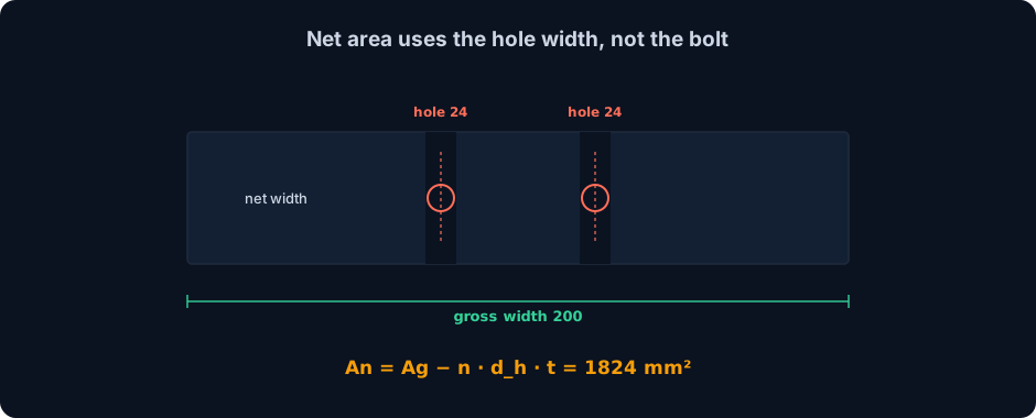
where n is the number of holes crossed, t is the plate thickness, and dh is the hole width used for net-area calculations. The single most common error here is using the bolt diameter for dh. The hole is always larger than the bolt, and the code adds even more on top for punching damage:
- AISC 360: the standard hole is the bolt diameter plus about 2 mm (1/16 in), and for net-area calculations you add a further 2 mm (1/16 in) for damage around the hole. An M20 bolt in a 22 mm standard hole is therefore computed with dh = 24 mm.
- NBR 8800: the same idea, standard hole equal to bolt plus 1.5 mm, plus 2 mm added for the net section, giving effectively bolt plus 3.5 mm.
The concept goes back a century. Once engineers moved from solid eyebars to riveted and bolted plates, they realised the reduced section at the fastener line, not the full bar, sets the fracture load. Salmon and Johnson trace the modern net-area and shear-lag treatment straight into today's AISC provisions. Throughout this article we use dh = 24 mm for M20 bolts, the AISC convention.
Staggered holes and the s squared over 4g rule
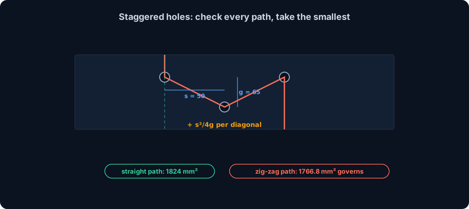
When bolts are staggered, the failure path can zig-zag from one hole to the next diagonally. A diagonal leg is longer than a straight cut, so it removes proportionally less area, and the code credits that back with the classic s²/4g term, one addition for every diagonal segment in the path:
An = Ag − ∑ dh · t + ∑ (s² / 4g) · t
Here s is the longitudinal spacing (pitch) between the two holes measured along the axis, and g is the transverse gage between the two lines. You evaluate every plausible path and the one giving the smallest net area governs. A zig-zag path crosses more holes than a straight one, but the s²/4g credits may or may not compensate.
Take the 200 × 12 mm plate from later in this article, with a gage g = 65 mm and a stagger pitch s = 50 mm. The straight path across two holes gives An = 2400 − 2 · 24 · 12 = 1824 mm². The zig-zag path crosses three holes but picks up two diagonal credits of s²/4g = 50²/(4 · 65) = 9.615 mm each: An = 2400 − 3 · 24 · 12 + 2 · 9.615 · 12 = 1766.8 mm². The zig-zag path is smaller, so it governs. Staggering the bolts made the critical section worse here, not better, which is precisely why you must check every path.
Shear lag and the effective net area
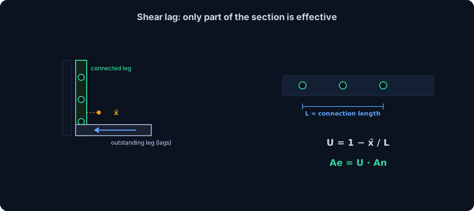
Net area assumes the whole reduced section resists uniformly. It does not, unless every element of the cross-section is connected. Bolt a single angle through one leg only and the force has to funnel from the outstanding, unconnected leg into the connected one through shear. Near the first bolts, the outstanding leg lags behind and carries less than its share. This is shear lag, and the code captures it with the reduction factor U:
Ae = U · An, with U = 1 − x̄/L
x̄ is the distance from the connected face to the centroid of the whole section, and L is the length of the connection (first bolt to last bolt). The further the centroid sits from the connection plane, and the shorter the connection, the more the section lags and the smaller U becomes. AISC Table D3.1 also lets you use simple lower-bound values, for example U = 0.80 for angles with four or more bolts per line, but the computed 1 − x̄/L is usually more generous and worth the arithmetic.
Two design levers fall straight out of this equation. Lengthening the connection (more bolts in the line, larger L) raises U toward 1.0. Connecting more of the section (both legs, or a gusset each side) raises U as well. A member with a generous gross area can still be governed by rupture purely because a short, one-sided connection throttled its effective area, as the worked angle below shows.
Worked example 1: the plate where yielding wins by 1.3 percent
A flat plate 200 × 12 mm in ASTM A36 steel (Fy = 250 MPa, Fu = 400 MPa) is spliced with two M20 bolts across its width in a single transverse line. The plate is connected across its full width, so there is no shear lag: U = 1.0. Work the two limit states.
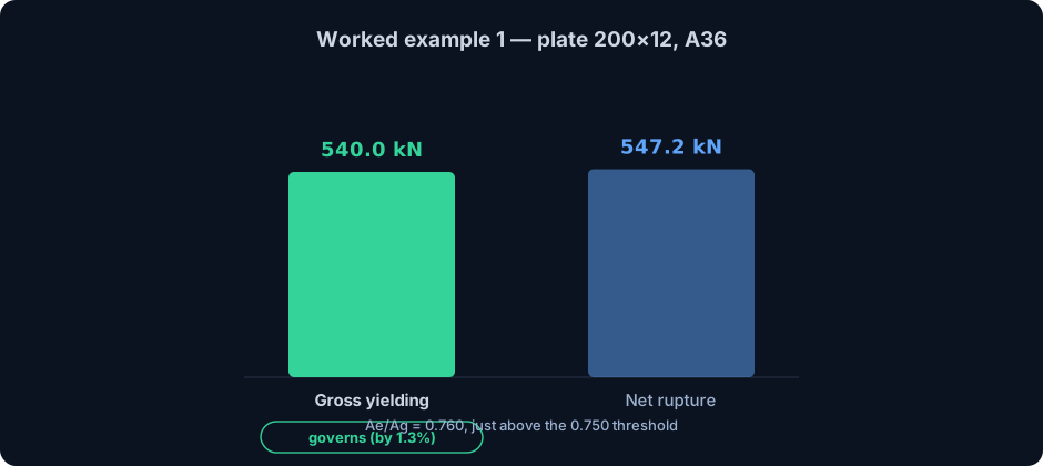
Areas. Ag = 200 · 12 = 2400 mm². Two holes at dh = 24 mm: An = 2400 − 2 · 24 · 12 = 1824 mm². With U = 1.0, Ae = 1824 mm². The holes have removed 24 percent of the area, so Ae/Ag = 0.760.
Yielding of the gross section: φtPn = 0.90 · 250 · 2400 = 540 000 N = 540.0 kN.
Rupture of the net section: φtPn = 0.75 · 400 · 1824 = 547 200 N = 547.2 kN.
Yielding governs, at 540.0 kN, but only by 1.3 percent. Losing a quarter of the area to holes was almost, but not quite, enough to hand the member to rupture. This razor-thin margin is the whole lesson: you cannot eyeball which limit state wins, you have to compute both. In the next section, pull the gross area of your own profile and repeat the two lines.
Try it: pull the gross area of your real profile
The gross area Ag is the starting point for both checks, and for a real rolled or cold-formed profile it is not a number you want to derive by hand. The calculator below is the live CalcSteel section engine, the same one behind the 3D editor. Pick a section, read its cross-sectional area A directly, and that is your Ag. Subtract n · dh · t for your bolt line to get An, apply the shear-lag U, and you are one multiplication away from both limit states.
For the flat-plate example above the area is trivial (200 × 12 = 2400 mm²), but the moment you reach for an angle, a channel or a built-up section, the gross area is worth reading straight off the engine rather than risking an arithmetic slip in the very first term.
Formula — hover a variable to highlight it on the drawing
Ix = [ b·h³ − (b − tw)·hw³ ] / 12= 1,845.6 cm⁴(hw = h − 2·tf)
Iy = [ 2·tf·b³ + hw·tw³ ] / 12= 141.9 cm⁴
Root fillets are neglected — rolled-section tables run 1–5% higher on Ix.
Parallel-axis theorem, live — Ix = Σ ( I₀ + A·d² )
| Part | A (cm²) | d (cm) | I₀ (cm⁴) | A·d² (cm⁴) | I₀ + A·d² (cm⁴) |
|---|---|---|---|---|---|
| Web | 10.25 | 0 | 286 | 0 | 286 |
| Flange (top) | 8.5 | 9.58 | 0.512 | 779.3 | 779.8 |
| Flange (bottom) | 8.5 | 9.58 | 0.512 | 779.3 | 779.8 |
| Σ = Ix | 287 | 1,558.6 | 1,845.6 |
Exact rectangle parts (web + two flanges) about the section centroid — the flange A·d² transfer terms are the whole story of the I-beam. Change any dimension above and watch the table re-derive.
Section properties
Moment of inertia Ix
1,845.6 cm⁴
1.846 × 10⁷ mm⁴
Moment of inertia Iy
141.9 cm⁴
1.419 × 10⁶ mm⁴
Area A
27.25 cm²
Mass
21.39 kg/m
Section modulus Sx
184.6 cm³
Section modulus Sy
28.39 cm³
Plastic modulus Zx
209.7 cm³
Plastic modulus Zy
43.93 cm³
Radius of gyration rx
8.23 cm
Radius of gyration ry
2.28 cm
Centroid x̄ (from left)
50 mm
Centroid ȳ (from bottom)
100 mm
Local slenderness — NBR 8800 / AISC 360 fingerprint
Flange
λ = b / 2·tf = 5.88
λp = 10.75 · λr = 28.28
Web
λ = hw / tw = 32.68
λp = 106.3 · λr = 161.2
Flexure limits per AISC 360 Table B4.1b (≈ NBR 8800 Annex F), fy = 250 MPa, E = 200 GPa — λp/λr scale with √(E/fy). Compact sections reach the full plastic moment Mp = Z·fy; non-compact and slender elements are capped by local buckling.
Closest standard profiles — matched by Ix against 876 real catalog sections
Ix = 1,845.6 cm⁴ (-0.0%)
Iy = 141.9 cm⁴ (-0.0%)
21.39 kg/mlightest
Best match — design checks
Ix = 1,844.2 cm⁴ (-0.1%)
Iy = 902.5 cm⁴ (+535.8%)
34.19 kg/m#2 by weight
Design checks
Ix = 1,838.7 cm⁴ (-0.4%)
Iy = 1,838.7 cm⁴ (+1195.4%)
43.96 kg/m#3 by weight
Design checks
Same 1,309-profile database that powers the CalcSteel 3D editor and profile pages — ABNT cold-formed (Ue, U, rounds), AISC (W, HSS, L, Pipe), European (IPE, HEA, HEB, HEM, UPN) and Indian (ISMB/ISMC) series. Opening a match carries your custom section along as the comparison baseline.
Worked example 2: the angle where shear lag hands it to rupture
Now a single angle L102 × 102 × 9.5 (Ag = 1845 mm², centroid x̄ = 28.7 mm) in ASTM A36, bolted through one leg with three M20 bolts at 75 mm pitch. Same steel as the plate, similar area, but a one-sided connection.
Shear lag. Connection length L = 2 · 75 = 150 mm. U = 1 − x̄/L = 1 − 28.7/150 = 0.809.
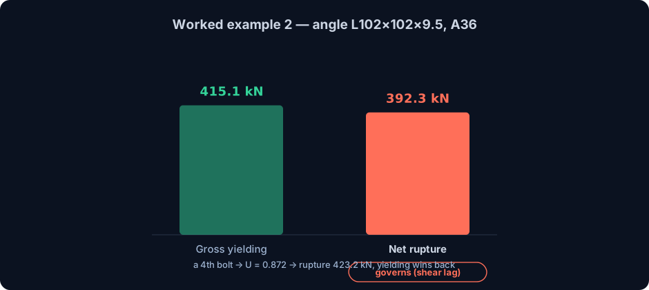
Areas. One hole through the connected leg: An = 1845 − 24 · 9.5 = 1617 mm². Effective net area Ae = 0.809 · 1617 = 1307.6 mm². Now Ae/Ag = 0.709, below the plate's 0.760.
Yielding: φtPn = 0.90 · 250 · 1845 = 415.1 kN. Rupture: φtPn = 0.75 · 400 · 1307.6 = 392.3 kN. This time rupture governs, at 392.3 kN.
The angle has almost the same gross area as many plates, yet shear lag pushed Ae low enough to flip the governing mode. And the fix is telling: add a fourth bolt, L grows to 225 mm, U rises to 0.872, rupture climbs to 423.2 kN, and yielding takes back control at 415.1 kN. One extra bolt, a different limit state, 6 percent more capacity, without changing the steel at all.
The same line, three codes: AISC 360, NBR 8800, Eurocode 3
Every major code runs the same two-limit-state check, they only dress the safety factors differently. The gross-yielding term always uses the yield stress and the net-rupture term always uses the ultimate stress; what changes is where the factor sits and how big it is.
| Code | Gross yielding | Net rupture |
|---|---|---|
| AISC 360 (LRFD) | φ = 0.90; 0.90 Fy Ag | φ = 0.75; 0.75 Fu Ae |
| NBR 8800 | γa1 = 1.10; Ag fy / 1.10 | γa2 = 1.35; Ae fu / 1.35 |
| Eurocode 3 | γM0 = 1.00; A fy / 1.00 | γM2 = 1.25; 0.9 Anet fu / 1.25 |
The three look different but land close together. AISC's 0.90 on yielding is nearly EN's γM0 = 1.00 (a factor of 1.0 on strength) and NBR's 1/1.10 = 0.909. On rupture, AISC's 0.75 sits between NBR's 1/1.35 = 0.741 and EN's combined 0.9/1.25 = 0.72. Eurocode folds an extra 0.9 onto the net term and treats shear lag through separate connection rules rather than a U factor inside Ae, but the philosophy is identical: a ductile check on the full section and a brittle check on the reduced one, with the reduced one penalised harder.
For the CalcSteel audience this matters because the same member can be verified against NBR 8800, AISC 360 or EN 1993 in the editor, and the governing limit state can shift slightly between them. The engineering is the same; only the partial factors move.
The crossover rule: predict the winner before you compute
You can settle which limit state governs with one inequality, before any number-crunching. Rupture governs when 0.75 Fu Ae < 0.90 Fy Ag, which rearranges to a pure ratio of areas:
Rupture governs when Ae/Ag < 1.2 · Fy/Fu
The right-hand side is a property of the steel alone. Evaluate it once per grade:
- ASTM A36 (Fy/Fu = 0.625): rupture governs when Ae/Ag < 0.750. You can lose up to 25 percent of the section before rupture takes over.
- ASTM A572 Gr.50 (Fy/Fu = 0.767): rupture governs when Ae/Ag < 0.920. Now even an 8 percent loss tips it to rupture.
This exposes a genuinely counter-intuitive result: higher-strength steel makes net rupture govern more often, not less. As Fy climbs toward Fu, the ductile yielding limit rises faster than the brittle rupture limit, so the brittle mode catches up and controls at ever-smaller hole losses. A single bolt line already removes more than 8 percent of most sections, so on Grade 50 and higher, rupture at the connection is the mode to watch by default. Our A36 plate sat at Ae/Ag = 0.760, a hair above 0.750, which is exactly why yielding scraped the win by 1.3 percent.
Five mistakes that flip the answer
- Using the bolt diameter as the hole width. The hole is the bolt plus clearance plus a damage allowance. An M20 bolt is computed with dh = 24 mm, not 20. This alone can shift the net area by several percent.
- Forgetting shear lag. Using An in the rupture equation instead of Ae = U An overstates the capacity, badly for angles, tees and channels bolted through part of the section.
- Checking only the straight hole path. With staggered bolts a zig-zag path can govern even though it crosses more holes. Evaluate every path and take the smallest net area.
- Mixing the resistance factors. 0.90 belongs to yielding, 0.75 to rupture. Swapping them, or carrying an AISC factor into an NBR or EN calculation, quietly moves the governing limit state.
- Assuming the bigger gross area is safe. A generous Ag means nothing if a short, one-sided connection throttles Ae. The angle example had ample gross area and still failed by rupture.
The short version
A bolted tension member is only as strong as the smaller of two numbers: 0.90 Fy Ag for ductile yielding over its length, and 0.75 Fu Ae for brittle rupture at the holes. Compute the net area with the hole width, not the bolt; add the s²/4g credit on staggered paths; reduce to the effective net area with the shear-lag U. Then let the crossover rule, Ae/Ag against 1.2 Fy/Fu, tell you which mode to expect, and remember that higher-strength steel biases the answer toward rupture. Check both, every time, because as the plate showed, the winner can come down to a single percent.
Sources
- 1.AISC 360-22, Specification for Structural Steel Buildings, Chapters D (tension members) and J4 (net section)
- 2.AISC Design Examples v15, Example D.2 (single-angle tension member)
- 3.Salmon, Johnson and Malhas, Steel Structures: Design and Behavior, Chapter 3 (tension members, net area and shear lag)
- 4.ABNT NBR 8800, Projeto de estruturas de aco e de estruturas mistas de aco e concreto de edificios
Try CalcSteel for free
Model, analyze and design steel structures in your browser. No install, no signup.
Open the 3D editor