Web Stiffeners: When the Web Needs Help Under a Concentrated Load
When a column, a reaction or a crane wheel lands on a thin web, AISC 360 J10 decides whether it yields or cripples, and when a bearing stiffener has to carry it.
Key takeaways
- A concentrated force funnels into a thin strip of web, so you always check two limit states: web local yielding (J10.2, phi 1.00) and web local crippling (J10.3, phi 0.75), and take the smaller.
- Crippling usually governs. It is a buckling mode at phi 0.75 driven by the web thickness squared, so a thin web runs out first.
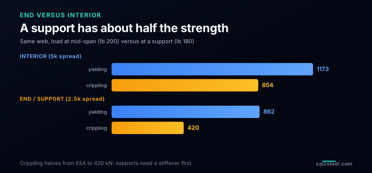
- A member end is about half as strong as an interior point (2.5k against 5k, 0.40 against 0.80), so supports need stiffeners before midspans do.
- When the force beats the web, a bearing stiffener carries it as a short column (J10.8). Size it by proportions, column strength and bearing, and bearing usually governs, not buckling.
- Bearing stiffeners (concentrated loads, J10) are not intermediate stiffeners (shear, Chapter G). Keep the two apart.
The most fragile part of the beam, hiding in plain sight
Every rolled beam and welded girder hides its most delicate part in plain sight: the web, the thin vertical plate that carries shear and holds the two flanges apart. When load spreads out over a long span the web copes fine. But the moment a concentrated force lands on a short length, a column bearing on the top flange, a beam reaction at a support, a crane wheel, a jack point, all of that force funnels into a narrow strip of web just above the fillet. That strip is a few millimetres thick, and it has just become the most stressed material in the whole member.
Two things can go wrong there, and they are not the same failure. The web can yield, squashing like soft metal right under the load, or it can cripple, folding out of plane like a drinks can pressed on its side. When either capacity runs out you have one honest fix: give the web help. That help is a web stiffener, a plate welded to the web to share the load and stop it buckling. This guide shows exactly when the web needs it, how AISC 360 Chapter J10 puts a number on it, and how to size the stiffener that carries the difference.
What a web stiffener actually is (and its two lookalikes)
A web stiffener is a steel plate, usually a flat bar, welded to the web to stiffen or strengthen it against a local effect. The name covers three jobs that beginners blur together, so pin them down first.
Bearing stiffeners, the subject of this guide
These sit directly under a concentrated load or over a support reaction, in line with the force. They run the full depth of the web, fit tight against the loaded flange, and act as a short column that carries the force past the web. When someone says a web needs help under a point load, this is the stiffener they mean.
Intermediate (transverse) stiffeners
These are spaced along a plate girder to raise the web's shear buckling resistance and, in deep thin webs, to anchor tension field action. They answer shear, not a concentrated force, and they do not need to bear on the flange. A different problem, covered by AISC Chapter G, mentioned here only so you never confuse the two.
Doubler plates
Instead of a rib across the web, a doubler thickens the web itself with a plate laid flat against it. It is the alternative when a bearing stiffener is awkward to fit, for example inside a column panel zone. The rest of this article is about the first kind, because that is what a concentrated load calls for.
The five limit states of a concentrated force
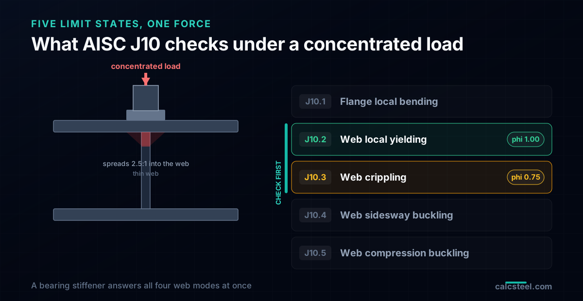
AISC 360 Chapter J10 does not ask one question about a concentrated force, it asks up to five, each a different way the flange or web can give out. Run through them and the logic of stiffeners falls out on its own.
- Flange local bending (J10.1): a tensile force pulls the flange away from the web and bends it like a plate. Relevant at moment-connection flanges, cured by a transverse stiffener opposite the flange.
- Web local yielding (J10.2): the web squashes under the load where it is thinnest, just above the fillet. A strength limit, phi = 1.00.
- Web local crippling (J10.3): the compressed web folds out of plane. A stability limit, phi = 0.75, and usually the one that governs.
- Web sidesway buckling (J10.4): the whole web bows sideways because the loaded flange can move relative to the other. Only when the compression flange is not braced.
- Web compression buckling (J10.5): a force applied at both flanges at once, for instance a beam framing each side of a column, buckles the full web height.
A bearing stiffener is the general cure: it carries the force as a column, so it answers web local yielding, web crippling, web sidesway buckling and web compression buckling in one move. The two you check first, and the two that decide whether you need a stiffener at all, are almost always web local yielding and web crippling.
Web local yielding (J10.2): the load spreads, then squashes
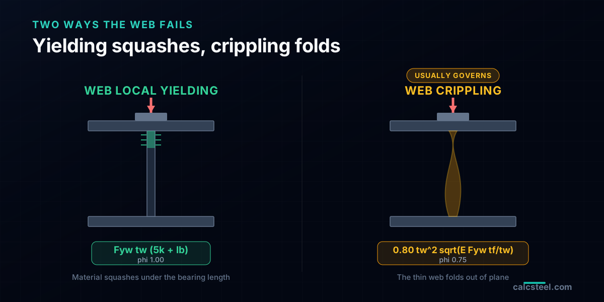
Picture the load spreading down into the web at a slope, roughly 2.5 to 1 through the flange and the fillet, until it reaches the thin web. The length of web that shares the load is the bearing length plus that spread. Yielding is reached when that length, times the web thickness, times the yield stress, equals the force:
Interior load: Rn = Fyw · tw · (5k + lb)
At or near the member end: Rn = Fyw · tw · (2.5k + lb)
where Fyw is the web yield stress, tw the web thickness, k the distance from the outer face of the flange to the toe of the fillet (use the design value kdes, not the k1 detailing dimension, a classic slip), and lb the bearing length of the load. This is a yielding limit, so phi = 1.00. Notice the end is worse: only half the spread is available, 2.5k against 5k, because there is no web on the outboard side to help.
Web local crippling (J10.3): the mode that usually wins
Crippling is a different animal. Instead of the material yielding, the slender web loses its shape and folds out of plane, the way a drinks can crumples when you press its wall. Because it is a buckling mode it is far less forgiving, and it carries phi = 0.75. The AISC expression packs the web and flange geometry into one formula:
Interior: Rn = 0.80 tw² [1 + 3(lb/d)(tw/tf)^1.5] √(E Fyw tf / tw)
At the end the leading constant halves to 0.40, and the bracket changes once lb/d passes 0.2. The halving is the same story as yielding: an end has web on one side only.
Two things make crippling the usual governor. The 0.80 (or 0.40) constant and the buckling nature pull the number down, and it is driven by tw squared, so a thin web is punished twice. On rolled shapes with stocky webs, yielding and crippling both clear ordinary reactions. On deep, thin-webbed plate girders, crippling is the first to run out.
Worked example: a plate girder under an interior column load
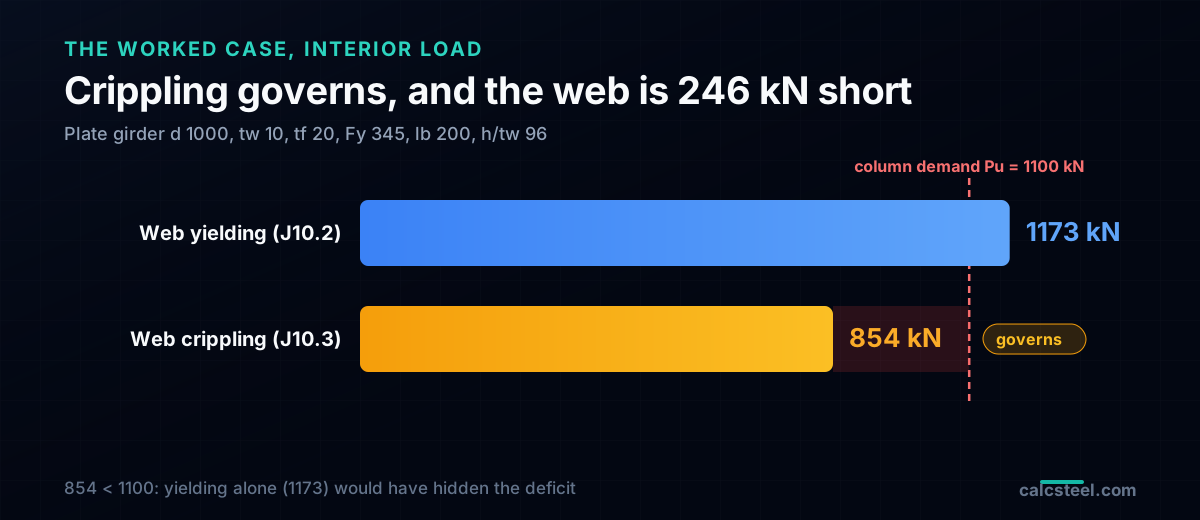
Take a welded plate girder 1000 mm deep, with a 10 mm web, 350 x 20 mm flanges, Fy = 345 MPa. A column lands on the top flange at midspan over a bearing plate lb = 200 mm long, delivering a factored force Pu = 1100 kN. The web-to-flange weld is an 8 mm fillet, so k = tf + weld = 28 mm. The web slenderness h/tw is 96, thin enough that a concentrated load is a real question. Run both checks:
| Limit state | Calculation | phiRn |
|---|---|---|
| Web local yielding (J10.2) | 1.00 · 345 · 10 · (5·28 + 200) | 1173 kN |
| Web local crippling (J10.3) | 0.75 · 0.80 · 10² · 1.212 · √(200000·345·20/10) | 854 kN (governs) |
| Demand Pu | factored column force | 1100 kN |
The web can take 854 kN before it cripples, the column delivers 1100 kN. It is short by 246 kN. Notice that yielding (1173 kN) looks safe on its own, and would have fooled you if you had checked only the bigger-looking equation. Crippling is the honest governor here. The web needs help: a bearing stiffener is required, and it will have to carry the full concentrated force as a column.
The support is only half as strong
Move the same girder's load to a support and the numbers drop, because an end is weaker on both counts. With a reaction Ru = 700 kN over a bearing lb = 180 mm:
- Web local yielding (end): Rn = 345 · 10 · (2.5·28 + 180) = 862 kN.
- Web local crippling (end): lb/d = 0.18, below 0.2, so the 0.40 constant applies: phiRn = 420 kN.
Yielding fell from 1173 to 862 kN, crippling from 854 to 420 kN, roughly half in each case. The 700 kN reaction sails past the 420 kN crippling limit. This is why bearing stiffeners so often appear at the supports of plate girders and crane runway beams even when the interior is fine: the same web is only half as strong where it ends. Keep the two cases straight, using the interior formula at a support is a real and unconservative mistake.
Try it: get the concentrated force first
Every J10 check starts with the concentrated force itself, the reaction or point load the web has to survive. Set your span, drop a point load where the column or support sits, and read the reaction straight off the diagram. Then carry that number into the yielding and crippling checks above. Change the position and watch how much larger a support reaction can be than a midspan point load, which is exactly why supports are the usual home of bearing stiffeners.
Max moment
45 kN·m
Max shear
30 kN
Max deflection
10.55 mm
= L/569
Bending stress σ
84.4 MPa
σ = M/Sx
Utilization
44.0%
NBR 8800 · δ ≤ L/250
Geometry & supports
Section
Ix 7999 cm⁴ · Sx 533 cm³ · 42.2 kg/m
Point loads (↓ positive)
None — add as many as you need.
Distributed loads (uniform or trapezoidal)
Model sketch
Diagrams — free PNG / SVG / CSV export, no watermark
Step-by-step — the calculation memory of YOUR beam
IPE 300 · L = 6 m · fy = 250 MPa
1. Reactions (equilibrium of the solved FEM model)
ΣFy = 0 · ΣM = 0
R_A = 30 kN · R_B = 30 kN
2. Peak shear (read from the SFD)
Vmax = |V(x)|max
Vmax = -30 kN @ x = 6 m
3. Peak moment (read from the BMD)
Mmax = |M(x)|max
Mmax = 45 kN·m @ x = 3 m
4. Peak deflection
EI = 15998 kN·m² (E = 200 GPa)
δmax = 10.55 mm @ x = 3 m = L/569
5. Elastic bending stress
σ = Mmax / Sx = 45.00 × 10³ / 533.3
σ = 84.4 MPa
6. Bending check — both codes, side by side
NBR 8800: σ ≤ fy/1.10 = 227.3 MPa · AISC 360: σ ≤ 0.90·fy = 225 MPa
NBR 37.1% PASS · AISC 37.5% PASS
7. Deflection check (serviceability — code-independent)
δ ≤ L/250 = 24 mm
10.55 mm / 24 mm = 44.0% PASS
Recomputed live from the current inputs by the direct-stiffness FEM engine — change any load and every step updates. Reproduce it by hand with the formulas in the sections below.
Lightest catalog profiles that pass (974 flexural candidates · NBR 8800)
| Profile | Std | Weight | Total steel | σ util | δ util | |
|---|---|---|---|---|---|---|
| W310x21 | AISC | 21 kg/m | 126 kg | 83% | 98% | |
| VS 300x23 | BR | 22.6 kg/m | 136 kg | 71% | 84% | |
| U 300x90x6.3 | BR | 23.1 kg/m | 139 kg | 82% | 98% | |
| U 300x100x6.3 | BR | 24.1 kg/m | 145 kg | 77% | 91% | |
| VS 250x25 | BR | 24.6 kg/m | 148 kg | 70% | 100% |
Elastic bending (σ = M/Sx vs fy/γa1, γa1 = 1.10 — NBR 8800) + deflection screening of the full flexural catalog. Lateral-torsional buckling, shear and local buckling are NOT checked here — run the full NBR 8800 / AISC 360 verification in the 3D editor.
Sizing the bearing stiffener as a short column (J10.8)
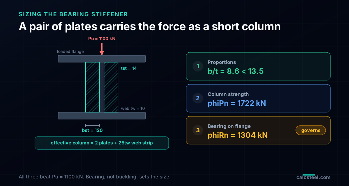
Once the web is short, the stiffener carries the force. AISC J10.8 treats a pair of bearing stiffeners, one each side of the web, as a short column: the two plates plus a strip of web acting together. Three checks size it, and for the 1100 kN case above they run like this.
1. Proportions
Each plate has to reach out under the flange and be thick enough not to buckle on its own. Minimum width bst ≥ bf/3 - tw/2 = 350/3 - 5 = 112 mm, so use 120 mm. To keep the outstand from local buckling, tst ≥ bst / (0.56 √(E/Fy)) = 120/13.5 = 8.9 mm, so 14 mm is comfortable (b/t = 8.6 against the 13.5 limit).
2. Column strength
The effective column is the two 120 x 14 plates plus a web strip 25tw = 250 mm wide (12tw at a member end), total area 5860 mm². Its effective length is 0.75h = 720 mm with K = 0.75, because the flanges hold both ends. That gives KL/r = 27, a very stocky column: Fcr = 327 MPa, phiPn = 1722 kN. Column buckling passes by a mile, which is the norm.
3. Bearing on the flange
The stiffener has to bear against the loaded flange without crushing the contact. After clipping the inner corners to clear the web-flange weld, the contact area is 2800 mm², so phiRn = 0.75 · 1.8 · Fy · Apb = 1304 kN. This is the check that actually governs the size, 1304 kN against the 1100 kN demand, with the column check far above.
So a pair of 120 x 14 mm stiffeners, fitted to bear, turns a web that failed at 854 kN into a detail good for 1100 kN. The lesson repeats: it is rarely the column that sizes a bearing stiffener, it is the bearing contact and the plate's own b/t limit.
Detailing: a stiffener drawn wrong carries nothing
The calculation is only half the job. A bearing stiffener detailed carelessly carries far less than the numbers promise.
- Fit to bear. The stiffener must contact the flange that receives the load. Under a top load, finish the top end to bear; over a support, the bottom. A gap means the web still takes the force first.
- Clip the corners. Cut a small corner off the inner edge so the stiffener clears the web-to-flange fillet weld. That is why the bearing contact width is less than the full plate width.
- Pair, not single. Use one plate each side of the web so the load stays centred. A one-sided stiffener bends the web and is only for light cases.
- Weld to the web. The web-to-stiffener weld carries the force into the stiffener, so size it for the force, not by eye.
- Full depth for bearing. A bearing stiffener runs the full clear web height. Partial-depth stiffeners belong to the intermediate (shear) family, not here.
When the web does not need help
Not every concentrated load calls for a stiffener, and adding one you do not need is wasted fabrication. Rolled wide-flange shapes have stocky webs, so a plain beam bearing on a wall or a modest column reaction usually checks out with nothing added. Run the J10.2 and J10.3 numbers first: if both phiRn beat the force, you are done.
The web needs help when the web is thin and the load is heavy: deep welded plate girders, crane runway beams under wheel loads, transfer girders picking up a column, and the supports of any of those. If your h/tw is up in the 90s and the load is hundreds of kN over a short bearing, expect to add a stiffener.
And do not confuse this with the intermediate stiffeners spaced along a girder web: those answer shear buckling (Chapter G), not a concentrated force. Same word, different check. A deep girder can carry both: bearing stiffeners at the loads and reactions, intermediate stiffeners in between for shear.
Common mistakes and FAQ
Assuming yielding governs because its number is bigger
Web yielding has phi = 1.00 and often looks larger, but crippling at phi = 0.75 and tw squared usually governs on thin webs. Always check both and take the smaller.
Using the interior formula at a support
Ends are half as strong: 2.5k not 5k, and 0.40 not 0.80. Using 5k+lb or the 0.80 constant at an end overstates capacity, which is the dangerous direction.
Forgetting to fit the stiffener to bear
A stiffener with a gap at the loaded flange does not deliver bearing, and the web fails first. Fit-to-bear is not optional on a bearing stiffener.
Confusing bearing and shear stiffeners
Bearing stiffeners sit under concentrated loads (J10). Intermediate stiffeners are spaced for shear (Chapter G). They are sized by completely different checks.
Ignoring the double-flange case
A force delivered at both flanges at once, such as a beam framing each side of a column, triggers web compression buckling (J10.5). A single top load does not, so do not carry that check where it does not apply.
Key takeaways
A concentrated force is a local problem with a local cure. Check web local yielding and web local crippling, take the smaller, and remember crippling usually wins on a thin web. Treat an end as half as strong as an interior point. When the force beats the web, size a bearing stiffener as a short column, and expect bearing on the flange, not buckling, to set its size. Keep bearing stiffeners (concentrated loads) apart from intermediate stiffeners (shear), and detail the stiffener to bear or it carries nothing. CalcSteel runs the J10 checks on every member as you model, and flags the web before it becomes a site problem.
Sources
- 1.AISC 360-22 Specification, Chapter J10 (Flanges and Webs with Concentrated Forces) and J7 (Bearing Strength)
- 2.AISC Steel Construction Manual, Part 9 (Design of Connecting Elements and Concentrated Forces)
- 3.Salmon, Johnson and Malhas, Steel Structures: Design and Behavior (plate girders: bearing and intermediate stiffeners)
Try CalcSteel for free
Model, analyze and design steel structures in your browser. No install, no signup.
Open the 3D editor