Load Combo: the Criterion Behind the Code, with a Worked Check
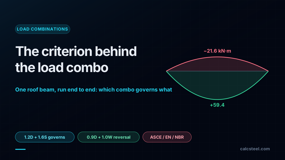
A load combo is not the sum of your loads. It is a criterion: the code's statement of how much of each load may act at once, and how far each has to be pushed, so the finished structure reaches a target reliability instead of an average Tuesday. This guide takes one ordinary roof beam, a 6 m span carrying dead, snow and wind uplift, runs every load case on the real CalcSteel engine, then builds the combinations by hand. The point it makes is the one the tables hide: the combo that sizes the beam for bending is not the combo that sizes its hold-down, and switch codes and the governing uplift on the same beam moves from 14.4 kN to 24.75 kN. For the full catalogue of ASCE 7, EN 1990 and NBR combinations, see the companion guide; here we derive why the numbers are what they are, and check one member end to end.
Key takeaways
- A load combination is a reliability criterion, not arithmetic. LRFD factors the demand up (1.2D, 1.6S) and the capacity down (φ = 0.9), so the design sits at a target reliability. The factor is large where the load is variable (1.6 on snow) and small where it is not (1.2 on dead).
- On the worked 6 m beam, the gravity combo 1.2D + 1.6S governs bending at Mu = 59.4 kN·m, while a completely different combination, 0.9D + 1.0W, governs the support: it flips the reaction to 14.4 kN of uplift. The combo that sizes the section is not the one that sizes the connection.
- The reason 0.9D + 1.0W exists is load reversal. Reduce the dead load to 90 percent and let the wind lead, and the beam that was pushing down is pulled up. No gravity combination ever shows this, which is exactly why the code writes a separate one.
- Change the code and the same beam gives a different answer. The uplift the hold-down must resist is 14.4 kN under ASCE 7, 22.5 kN under NBR 8681 and 24.75 kN under EN 1990, because each code treats the favorable dead load and the wind factor differently.
- Strength is not the only combination. Serviceability uses the unfactored characteristic loads: the same beam deflects 24.8 mm under snow, right at the L/240 limit, so a member that passes bending at 84 percent can be governed by a combination that carries no load factors at all.
A load combo is a criterion, not a sum
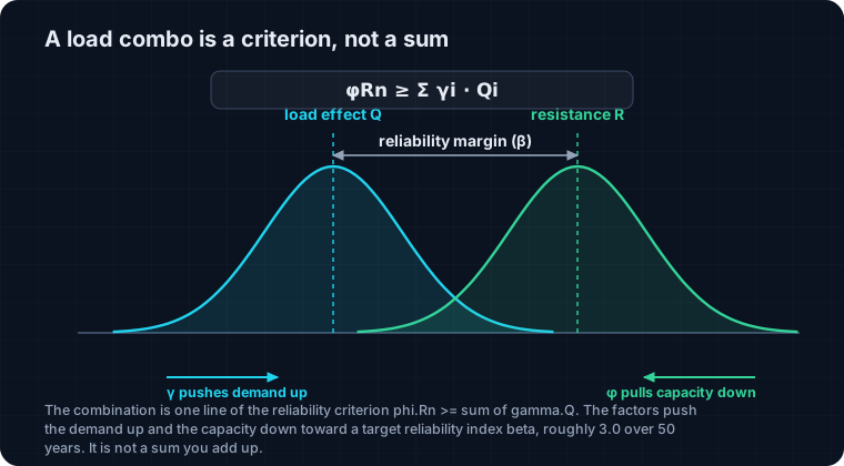
The first time you meet load combinations they look like bookkeeping: add the dead load to the live load, maybe throw in wind, and design for the total. That picture is wrong in a way that matters. Every load on a structure is a random variable with its own scatter. The dead load barely moves: you can count the steel and the slab. The snow, the wind and the crowd swing wildly from one year to the next. A load combination is the code's way of saying how much of each variable load can plausibly act at the same instant, and how hard to lean on each one, so the finished structure reaches a chosen level of safety.
That level is written as a target reliability index, roughly β ≈ 3.0 over a 50 year life for ordinary gravity members, which is a notional probability of reaching a limit state of about one in a thousand. You never see β on a drawing. What you see is its fingerprint: the load factors and the resistance factor. In LRFD the safety format is one inequality,
φRn ≥ Σ γi Qi
the factored resistance on the left, the factored load effects on the right. ASD writes the same idea the other way, Rn/Ω ≥ ΣQi, with one safety factor instead of many. Either way, a load combo is a line in that criterion, not a sum you happen to add up. The rest of this article makes that concrete on a single beam. For the full list of combinations across codes, our load combinations explained guide is the catalogue; this one is the reasoning behind it.
Why 1.2 on dead but 1.6 on snow
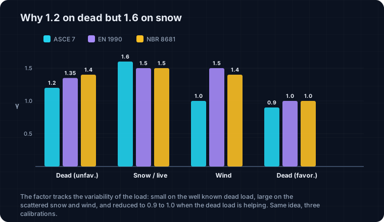
If the factors were about pessimism you would put the same one on everything. They are not. They come from calibration: in the 1980s Ellingwood, Galambos and colleagues fitted the LRFD factors so that a wide range of members would land near the same target β, given the measured variability of each load. The result reads straight off the statistics.
Dead load has a low coefficient of variation, so its factor is close to one: 1.2 in ASCE 7, 1.35 in EN 1990, 1.4 in NBR 8681. Live, snow and wind scatter far more, so they carry the heavy factors, 1.5 to 1.6. Wind at strength level already sits near its extreme, which is why modern ASCE 7 uses 1.0W rather than the old 1.6W. And when two variable loads appear in the same combination, only one leads at its full factor; the others are accompanying actions, cut by a companion factor (ψ0 in EN 1990, the 0.5 multipliers in ASCE 7) because two independent loads rarely peak in the same hour. That single idea, not-all-maxima-at-once, is most of what a combination encodes.
The mirror image is the resistance factor φ, or the material factor γM in Europe. The demand is pushed up and the capacity is pulled down, and the gap between them is the reliability you cannot see. Keep that in mind for the worked check at the end: the 0.9 on the capacity side is doing the same job as the 1.6 on the load side.
One beam, three load cases
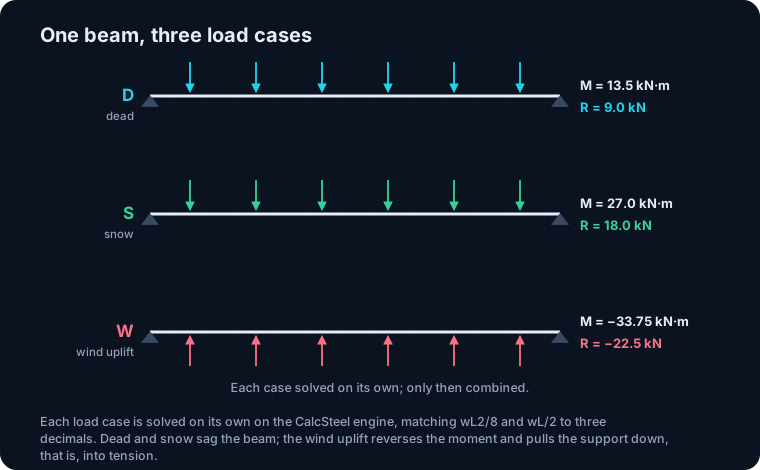
Here is the member. A simply supported roof beam, span 6 m, an IPE 200 in S355 steel, spaced so its tributary strip carries three loads: a dead load D = 3.0 kN/m from the roof build-up and the beam itself, a snow load S = 6.0 kN/m, and a wind uplift W = 7.5 kN/m, the net suction a gust pulls on a light roof. Uplift is the interesting one: it acts upward, against gravity.
The right way to handle this, and the way the CalcSteel engine does it, is to solve each load case on its own and only combine the results afterward. Mixing the loads before you analyse throws away the ability to weight them differently, which is the whole point of a combination. Run alone on the engine, the three cases give:
D by itself: midspan moment 13.5 kN·m sagging, support reaction 9.0 kN bearing. S by itself: 27.0 kN·m and 18.0 kN. W uplift by itself: −33.75 kN·m, the moment reversed because the load is upward, and a reaction of −22.5 kN, meaning the support is now being pulled down, that is, the connection is in tension. Each of these matches the hand calculation wL²/8 and wL/2 to three decimals. These three numbers are the raw material every combination below is built from.
Building the ASCE 7 combinations
Now assemble them. ASCE 7-22 gives seven LRFD combinations; on a roof beam with no floor live load, four are live and the rest reduce to these. Superposing the single case results with the right factors:
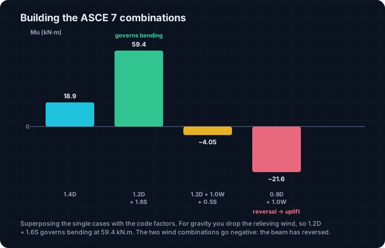
1.4D → 18.9 kN·m. 1.2D + 1.6S → 59.4 kN·m. 1.2D + 1.0W + 0.5S → −4.05 kN·m. 0.9D + 1.0W → −21.6 kN·m.
Two habits decide the right answer. For the gravity cases you drop the wind term, because uplift relieves the sagging and including it would be unconservative; for the uplift cases you drop the snow, for the same reason. That is why the governing gravity value is the clean 1.2D + 1.6S = 59.4 kN·m, snow leading at its full 1.6, with wind left out. This is the number that sizes the beam for bending. But look at the last two combinations: they went negative. That is not a rounding artefact. The beam has reversed, and the next section is about why that matters more than the headline moment.
The envelope, and what it hides
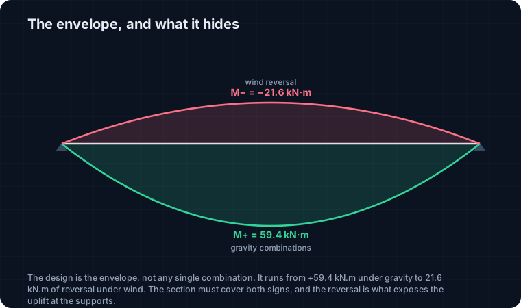
You never design for one combination. You design for the envelope: the most positive and the most negative value any combination produces at each point. On this beam the envelope at midspan runs from M+ = 59.4 kN·m, the bottom fibre in tension under gravity, down to M− = −21.6 kN·m, the top fibre in tension when the wind wins. The section has to cover both signs, and a symmetric I-section does, but the two ends of that envelope come from two different worlds.
The positive end is a gravity combination and it feels familiar: more snow, bigger moment, size the section. The negative end is the wind combinations flipping the beam over. If you only ever plotted the gravity combos you would see a tidy set of sagging diagrams and conclude the beam is fine. The envelope is what stops you: it forces the two wind combinations onto the same picture, and the reversal becomes impossible to miss. That reversal is not really about the midspan moment, which is modest. It is about the supports, and that is the criterion the next section is built around.
Why 0.9D + 1.0W is a combination on its own
Dead load is usually your friend. It holds the roof down. So the dangerous case for uplift is not the most wind with the most gravity, it is the most wind with the least gravity. That is precisely what 0.9D + 1.0W encodes: it deliberately shrinks the helpful dead load to 90 percent, then applies the full wind, to expose what happens when the thing that was holding the beam down is at its minimum.
On our beam the arithmetic is stark. Under gravity the support delivered 39.6 kN of bearing. Under 0.9D + 1.0W it becomes 0.9 × 9.0 − 22.5 = −14.4 kN: 14.4 kN of uplift. The reaction did not just get smaller, it changed sign. A bearing detail, a beam sitting in a pocket, does not care about a number that points up; the hold-down, the anchor or the uplift connection, cares about nothing else. Skip this combination and you will size the connection for the wrong sign entirely, and a wind event, not an overload, is what finds the mistake. This is the same reasoning behind the governing load case that decides a tie: the case that governs is rarely the one that looks heaviest.
Same beam, three codes, three uplifts
The criterion is universal; the numbers are jurisdictional. Take the identical beam and ask three codes for the uplift the hold-down must resist:
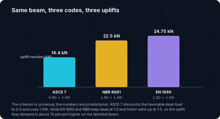
ASCE 7 (0.9D + 1.0W) → 14.4 kN. NBR 8681 (1.0D + 1.4W) → 22.5 kN. EN 1990 (1.0G + 1.5W, expression 6.10) → 24.75 kN.
Same physics, three answers, and the spread is large: the European uplift is about 70 percent higher than the American one. Two choices drive it. ASCE 7 discounts the favorable dead load to 0.9, while EN 1990 and NBR keep it at 1.0 for the uplift case; and the wind factor is 1.0 at strength level in ASCE 7 but 1.4 to 1.5 in the other two. Neither is more correct: each is calibrated to its own target reliability and its own wind statistics. The practical warning is simple. Detail a Brazilian or European roof to the ASCE uplift and the hold-down is undersized by half a connection. The combination is where the code you are actually working under enters the calculation, and it is not interchangeable.
The worked check: does the IPE 200 pass?
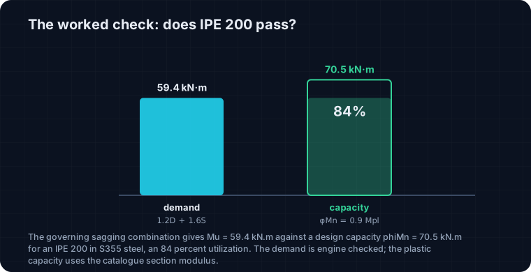
Bring it home with a real check against the governing sagging combination, Mu = 59.4 kN·m. The section is an IPE 200, a compact shape, so it develops its full plastic moment. Using the catalogue plastic modulus Wpl = 220.6 cm³ and Fy = 355 MPa:
Mpl = Wpl × Fy = 220.6 × 355 = 78.3 kN·m, φMn = 0.9 × 78.3 = 70.5 kN·m ≥ 59.4 kN·m → 84 percent.
It passes with room to spare on bending. One caution worth stating: take the plastic modulus from the section tables, not from a quick solver. The standalone engine reports a plastic modulus of 110.7 cm³ for this shape, about half the true 220.6, a known quirk of computing Zx outside the app, so the demand side here is engine and hand checked, while the capacity side leans on the published section properties. On the uplift side, the connection carries 14.4 kN of tension under ASCE and up to 24.75 kN under EN 1990: a small number, but one the bearing detail would never have caught. The beam is fine; the combination told you which two checks to actually run.
Serviceability is another combination again
Strength is not the last word, and here it is not even the governing one. The serviceability limit state uses a different combination: the unfactored characteristic loads, no γ on anything, companion actions reduced by ψ factors. You are no longer asking whether the beam breaks, you are asking whether it sags, cracks the ceiling or bounces underfoot.
Run the deflection on the same beam under characteristic snow, δ = 5wL⁴/384EI = 24.8 mm, which is very nearly L/240 = 25.0 mm, the usual total-load limit; add the dead load and the total reaches 37.2 mm. So the member that passed bending comfortably at 84 percent is, at serviceability, sitting right on its limit under a combination that carries no load factors at all. A different limit state, a different combination, and often a different section governs. It is common for a roof purlin or a long floor beam to be chosen by deflection, not by strength, and the only way to know is to run both combinations rather than assuming the factored one is always the harshest.
Try it: build the combinations yourself
Enter the same three loads below, D, S and the wind uplift, and watch the calculator assemble the LRFD combinations, flag the governing one for bending, and flip the sign on the uplift case. Switch the code and the uplift on the support moves with it, the 14.4 kN to 24.75 kN spread from a few sections up. It is the fastest way to feel why the combination, not the load, is the thing that decides your member.
NBR 8681
82.6 kN
governing ULS
ASCE 7-16/22
71 kN
governing ULS
EN 1990
84 kN
governing ULS
Code spread
18.3%
EN 1990 governs
Governing ULS by code — parcel makeup
NBR 8681
Ultimate (ULS / ELU)
Serviceability (SLS / ELS)
ASCE 7-16/22
Ultimate (ULS / ELU)
Serviceability (SLS / ELS)
EN 1990
Ultimate (ULS / ELU)
Serviceability (SLS / ELS)
24 combinations across 3 codes · math in SI, display in kN
Five ways load combos go wrong
The mistakes cluster, and every one of them is a combination error rather than an analysis error:
1. Mixing service and factored worlds. Feeding unfactored ASD loads into LRFD combinations, or checking a factored demand against an allowable stress. Pick one format and stay in it.
2. Forgetting the reversal combination. Designing every support for bearing and never running 0.9D + 1.0W, so uplift connections are simply missing. This is the failure that a windstorm finds first.
3. Factoring an accompanying load as if it led. Putting the full 1.6 or 1.5 on a snow that is only accompanying the wind, instead of its ψ0 companion value. It inflates the demand and hides which action really governs.
4. Sign errors on wind. Treating uplift as a downward load, which quietly deletes the reversal and leaves the whole point of the exercise on the floor.
5. Borrowing factors across codes. Using ASCE load factors with EN companion values, or vice versa. Each set is calibrated together; a hybrid is calibrated to nothing. When in doubt, let the combinations catalogue or the tool below generate the set for the code you are actually working under.
Sources
- 1.ASCE/SEI 7-22, Minimum Design Loads and Associated Criteria for Buildings and Other Structures (Chapter 2, Combinations of Loads)
- 2.AISC 360-22, Specification for Structural Steel Buildings
- 3.EN 1990:2002, Eurocode 0, Basis of Structural Design (expressions 6.10, 6.10a/b and companion factors)
- 4.ABNT NBR 8681:2003, Acoes e seguranca nas estruturas (combinacoes de acoes)
- 5.Ellingwood, Galambos, MacGregor, Cornell, Development of a Probability-Based Load Criterion for American National Standard A58 (NBS SP577)
Try CalcSteel for free
Model, analyze and design steel structures in your browser. No install, no signup.
Open the 3D editor