Support Settlement: The Forces a Continuous Beam Invents When a Column Sinks
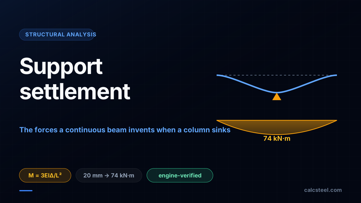
Support settlement puts real bending moments into a continuous beam with no load applied at all. This guide works the force method by hand on a two-span steel beam, then checks every number against the CalcSteel FEM engine to three decimals: a 20 mm sink invents 74 kN·m out of nothing.
Key takeaways
- A support that settles feeds forces into a continuous beam even under zero external load, because the structure is statically indeterminate and the extra supports refuse to let it move freely.
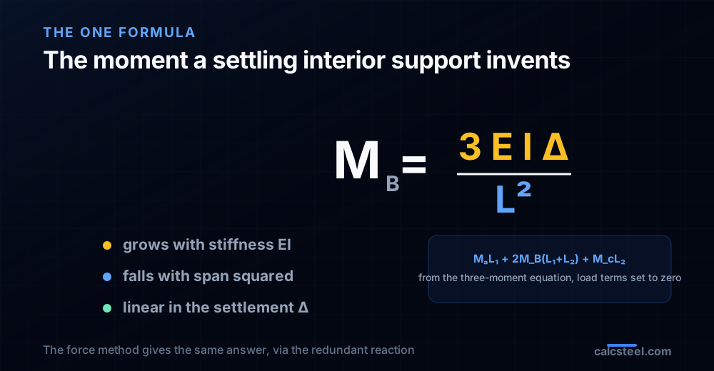
- The invented moment over a settling interior support is M = 3EIΔ/L² for a two-span beam: it grows with the beam's own stiffness EI and shrinks with the square of the span, so stiff short spans suffer most.
- On our IPE 400 two-span beam, sinking the middle support 20 mm invents a 74.1 kN·m sagging moment that the CalcSteel engine reproduces to three decimals, and it points the opposite way to the gravity hogging.
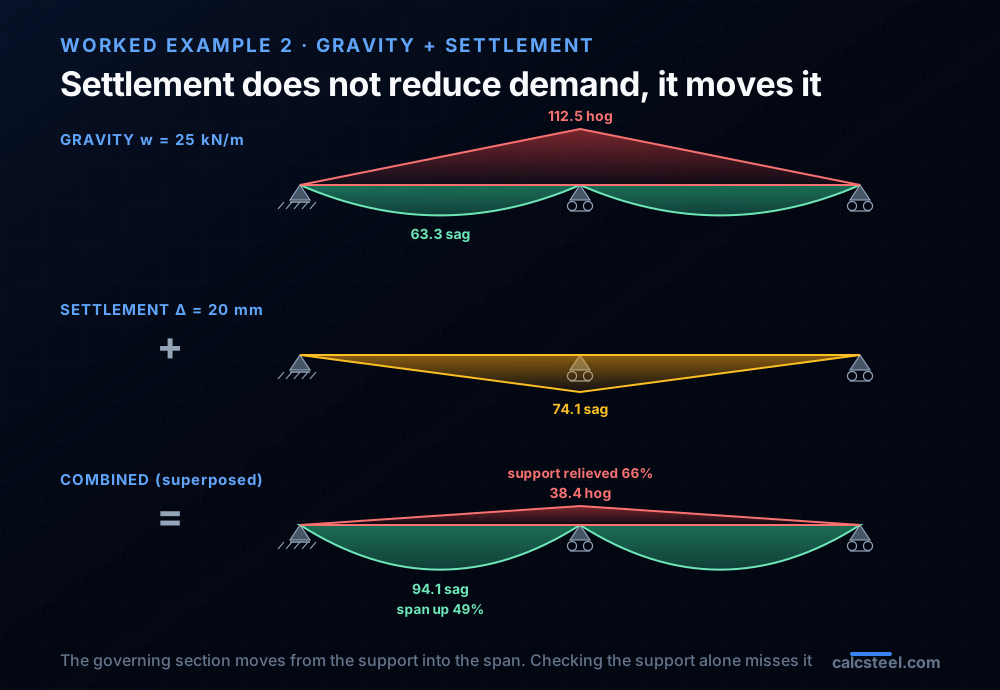
- Settlement does not reduce demand, it moves it: the same 20 mm relieves the interior hogging by 66%, from 112.5 to 38.4 kN·m, but pushes the span sagging up 49%, from 63.3 to 94.1 kN·m, and the governing section changes.
- A uniform settlement of every support does nothing to the internal forces; only differential settlement, the relative sink between supports, invents moments, which is exactly what a foundation report has to bound.
Forces out of nothing
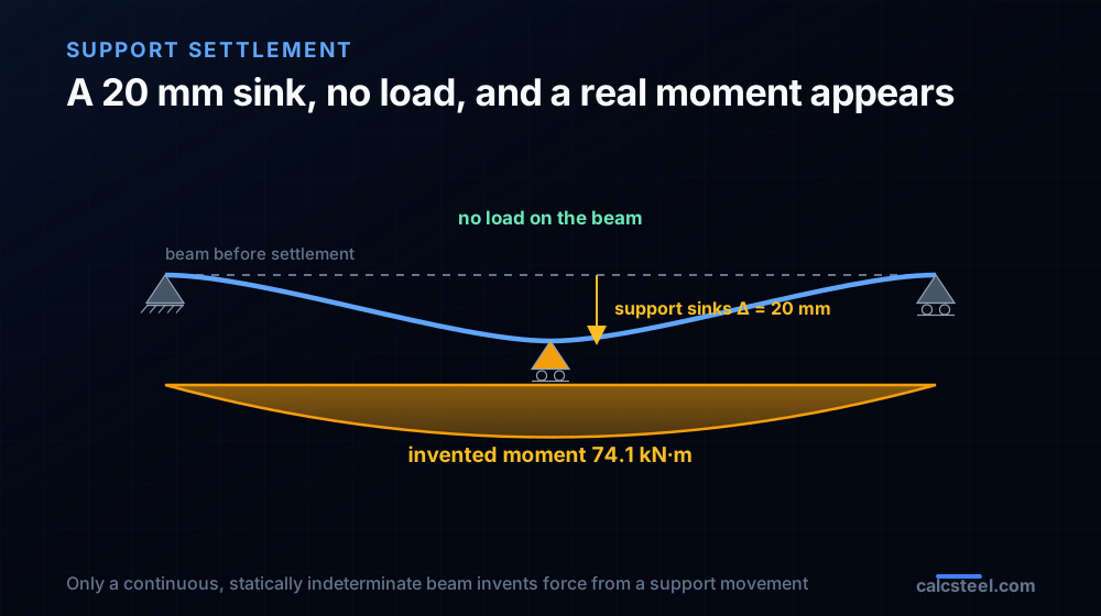
Here is a result that unsettles every student the first time they meet it. Take a continuous steel beam, apply no load at all, and let one of its supports sink by twenty millimetres. The beam now carries a real bending moment, large enough to matter in design, invented out of a movement with no force behind it. Nothing was placed on the beam. A column underneath it simply settled, and the steel found itself stressed.
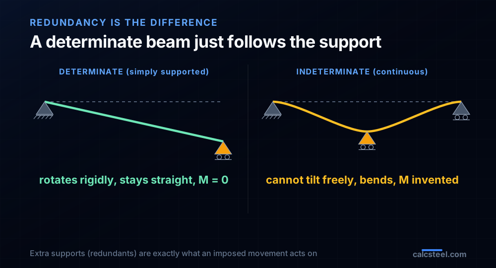
This is support settlement, and it is one of the sharpest lessons in Análise Estrutural and Estruturas I. It only happens in statically indeterminate structures, and it is the clearest proof that an indeterminate structure is a different animal from a determinate one. A simply supported beam does not care if a support drops: it just tilts and rides along, unstressed. A continuous beam over three or more supports cannot tilt freely, so when one support moves, the beam is forced to bend to stay attached to all of them, and bending means moment.
We will work the whole thing end to end on a real beam: a two-span IPE 400, spans of 6 m, and a 20 mm sink of the middle support. You will see where the invented moment comes from, compute it by hand with the 3EIΔ/L² formula and the force method, and then watch what happens when settlement is added on top of ordinary gravity load. Every number below was produced by the CalcSteel finite element engine and checked against the closed form to three decimals.
We wrote it for three readers. If you are a student, this is the worked example that finally makes indeterminacy concrete. If you are a practising or freelance engineer, it is the reasoning you reach for when a geotechnical report hands you a differential settlement and asks what it does to the frame. And if you have ever wondered why the codes make you check settlement at all, this article is the answer, on one beam. The free CalcSteel beam calculator runs in your browser with no login for the math, and you can size the members this article stresses.
What settlement is, and why only the differential part bites
Settlement is the vertical downward movement of a support as the ground beneath it compresses under load. Every foundation settles a little; the question is always how much, and how evenly. It matters to split it into two parts.
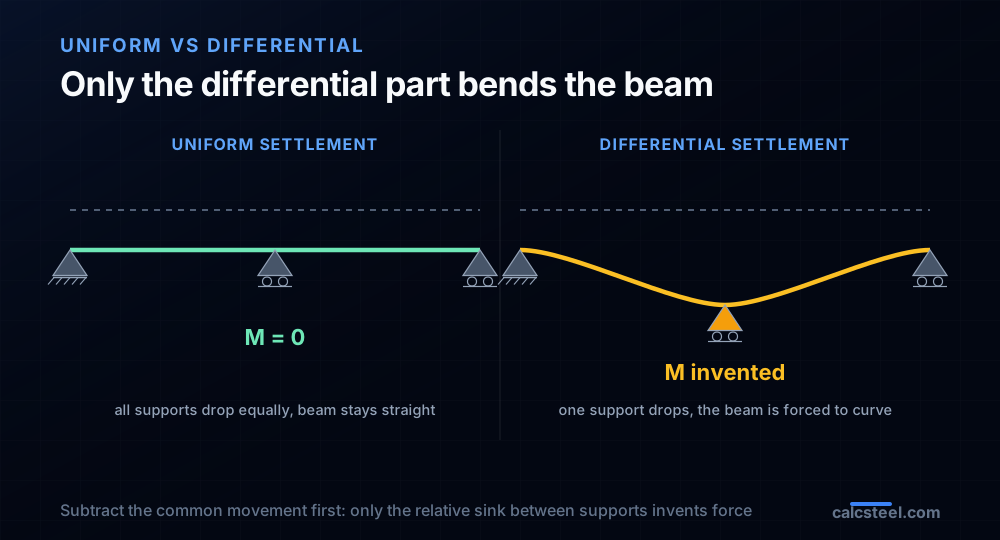
Uniform settlement is when every support of a structure drops by the same amount. The whole building moves down as one rigid block. It can crack services and tilt a floor relative to the street, but it puts no extra internal force into a continuous beam, because the beam keeps the same shape: if A, B and C all fall 20 mm together, the beam has not been bent at all.
Differential settlement is the one that stresses steel. It is the relative movement between supports, one column sinking more than its neighbours. That is what bends a continuous beam, and it is the number a geotechnical report is really trying to bound when it quotes an allowable angular distortion, typically something like L/500 between adjacent columns for a framed structure. Our worked example is pure differential settlement: A and C hold their level, and only B drops.
The physical cause is worth keeping in view, because it decides how permanent the effect is. Settlement comes from the soil consolidating, from a footing sized a little generously on one side and tightly on another, from a new load next door, from a water table that moved. Some of it is immediate and some develops over months. A moment invented by settlement is a locked-in force: unlike a live load it does not come and go, it sits in the structure until the ground stabilises or the beam is releveled.
Why an indeterminate beam invents forces and a determinate one does not
The whole phenomenon lives in one word: redundancy. A structure is statically indeterminate when it has more supports (or more members) than equilibrium strictly needs. Those extra supports are called redundants, and they are exactly what settlement acts on.
Look at the two beams side by side. A simply supported beam rests on two supports, a pin and a roller. Drop the roller by any amount and the beam simply rotates about the pin as a rigid body: it stays perfectly straight, no curvature, no moment. It is determinate, and equilibrium alone fixes its reactions, so an imposed movement changes nothing internal. The beam has enough freedom to follow the support.
Now add a third support in the middle and you have a continuous beam, indeterminate to the first degree. It no longer has the freedom to stay straight when one support moves. Drop the middle support and the beam is pulled down there while the ends are held up; to stay attached to all three it must bend into an S shape, and that curvature is bending moment. The redundant support is the one imposing the incompatibility, and the beam pays for it in stress.
This is why settlement is a pure test of indeterminacy. The moment it invents is proportional to how hard the redundant fights the movement, which is the beam's own stiffness. That is the physical meaning of the EI that is about to appear in the formula: the stiffer the beam, the harder it resists being bent by the settling support, and the larger the invented moment. It is the same indeterminacy that makes a continuous beam efficient under load, working here against you. If you want the formal count of redundants before you start, our note on static determinacy and stability does the bookkeeping, and the wider picture is in statically indeterminate structures.
The formula: 3EIΔ/L² and where it comes from
For the case in this article, a two-span continuous beam of equal spans L with simple ends, the moment invented over the settling interior support has a clean closed form:
MB = 3EIΔ / L²
where E is the elastic modulus, I the second moment of area of the section, Δ the differential settlement of the interior support, and L the span. Read what it says. The moment is proportional to EI, the beam's flexural stiffness, so a stiffer or deeper section invents a larger settlement moment for the same sink. It is inversely proportional to L², so short spans are punished far more than long ones. And it is linear in Δ, so twice the settlement is twice the moment.
The formula falls straight out of the three-moment equation (Clapeyron's theorem), the classical tool for continuous beams. In its general form, for two spans meeting at support B with settlements δ at each support, the theorem reads
MAL₁ + 2MB(L₁+L₂) + MCL₂ = −6EI[ (δA−δB)/L₁ + (δC−δB)/L₂ ] + load terms
For our case there is no load, the ends are simple so MA = MC = 0, the spans are equal (L₁ = L₂ = L), and only B settles (δA = δC = 0, δB = Δ). Substitute and the equation collapses to 4MBL = 12EIΔ/L, which is MB = 3EIΔ/L². The same answer comes from the force method: remove the interior support to get a simply supported primary beam over the double span, then find the redundant reaction that pushes the released point back down by exactly Δ. That reaction, times the geometry, is the moment. It is worth doing once by hand, and it is the reasoning our worked example follows.
Worked example 1: a 20 mm sink invents 74 kN·m from nothing
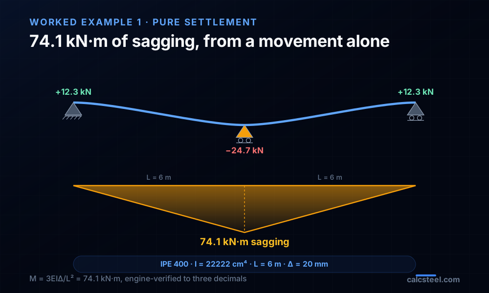
Now the number. Our beam is a two-span continuous IPE 400, two equal spans of L = 6 m, pinned at end A, a roller at the interior support B, and a roller at end C. The section's second moment of area, as the CalcSteel engine computes it from the geometry, is I = 22 222 cm⁴, and the steel modulus is E = 200 GPa. Apply no load, and sink support B by Δ = 20 mm.
Straight from the formula:
MB = 3EIΔ/L² = 3 × (20 000 kN/cm²) × (22 222 cm⁴) × (2 cm) / (600 cm)² = 74.1 kN·m.
Twenty millimetres of sink, no load on the beam, and it carries 74.1 kN·m. To feel the scale, that is more than half of what a full 25 kN/m gravity load would put over the same support, and it appeared from a movement alone. Two more features matter:
- It is sagging, not hogging. Because the support drops, the beam sags into the dip and the tension goes on the bottom fibre over the support. That is the opposite sense to the hogging a downward load produces there, and it is why settlement can either help or hurt depending on what else is acting.
- It sheds the interior support's load. The invented reactions are −24.7 kN at B (the support is being unloaded, even pulled upward relative to its gravity share) and +12.3 kN at each of A and C. The sinking support hands its load to its neighbours.
We built this exact beam in the CalcSteel FEM engine as a control, using the force method the engine can express: the released double span deflects 0.081 mm per kN at midspan, matching the closed-form flexibility L³/6EI to six figures, and the reaction that drives it down 20 mm induces 74.07 kN·m, agreeing with the hand value to three decimals. The invented moment is not a modelling artefact. It is as real as any load moment, and the steel has to carry it.
Try it: the free beam calculator
The fastest way to build intuition for stiffness and span is to change a beam and watch the numbers move. Here is the CalcSteel beam calculator, live on this page. Set the span, the section and the load, and it solves the beam and draws the shear and bending moment diagrams instantly, with the support reactions.
Start with a single 6 m span and an IPE 400 to get the feel of the section this article uses, then change the profile and watch how the stiffness EI drives the deflection. Remember the lesson of the formula: settlement moment scales with that same EI, so a section that deflects little under load is a section that invents a large moment under settlement. To see the continuous, three-support beam and impose a real support movement, model it in the full CalcSteel editor, where the same FEM engine that produced every number above runs on the whole structure.
It is the real solver, not a preview: unlimited runs, free, no login required for the math. If it opens in its own tab, here is the direct link to the beam calculator. For the reactions on their own, the beam reaction forces guide is the companion read.
Max moment
45 kN·m
Max shear
30 kN
Max deflection
10.55 mm
= L/569
Bending stress σ
84.4 MPa
σ = M/Sx
Utilization
44.0%
NBR 8800 · δ ≤ L/250
Geometry & supports
Section
Ix 7999 cm⁴ · Sx 533 cm³ · 42.2 kg/m
Point loads (↓ positive)
None — add as many as you need.
Distributed loads (uniform or trapezoidal)
Model sketch
Diagrams — free PNG / SVG / CSV export, no watermark
Step-by-step — the calculation memory of YOUR beam
IPE 300 · L = 6 m · fy = 250 MPa
1. Reactions (equilibrium of the solved FEM model)
ΣFy = 0 · ΣM = 0
R_A = 30 kN · R_B = 30 kN
2. Peak shear (read from the SFD)
Vmax = |V(x)|max
Vmax = -30 kN @ x = 6 m
3. Peak moment (read from the BMD)
Mmax = |M(x)|max
Mmax = 45 kN·m @ x = 3 m
4. Peak deflection
EI = 15998 kN·m² (E = 200 GPa)
δmax = 10.55 mm @ x = 3 m = L/569
5. Elastic bending stress
σ = Mmax / Sx = 45.00 × 10³ / 533.3
σ = 84.4 MPa
6. Bending check — both codes, side by side
NBR 8800: σ ≤ fy/1.10 = 227.3 MPa · AISC 360: σ ≤ 0.90·fy = 225 MPa
NBR 37.1% PASS · AISC 37.5% PASS
7. Deflection check (serviceability — code-independent)
δ ≤ L/250 = 24 mm
10.55 mm / 24 mm = 44.0% PASS
Recomputed live from the current inputs by the direct-stiffness FEM engine — change any load and every step updates. Reproduce it by hand with the formulas in the sections below.
Lightest catalog profiles that pass (974 flexural candidates · NBR 8800)
| Profile | Std | Weight | Total steel | σ util | δ util | |
|---|---|---|---|---|---|---|
| W310x21 | AISC | 21 kg/m | 126 kg | 83% | 98% | |
| VS 300x23 | BR | 22.6 kg/m | 136 kg | 71% | 84% | |
| U 300x90x6.3 | BR | 23.1 kg/m | 139 kg | 82% | 98% | |
| U 300x100x6.3 | BR | 24.1 kg/m | 145 kg | 77% | 91% | |
| VS 250x25 | BR | 24.6 kg/m | 148 kg | 70% | 100% |
Elastic bending (σ = M/Sx vs fy/γa1, γa1 = 1.10 — NBR 8800) + deflection screening of the full flexural catalog. Lateral-torsional buckling, shear and local buckling are NOT checked here — run the full NBR 8800 / AISC 360 verification in the 3D editor.
Worked example 2: settlement plus gravity, and where the demand moves
Pure settlement is the clean teaching case, but a real beam carries load at the same time. So put the gravity back: the same two-span IPE 400 now carries a uniform w = 25 kN/m, and then support B settles the same 20 mm. Because the beam is linear elastic, the two effects superpose exactly, so we solve each and add.
Gravity alone
The continuous beam under uniform load is a standard case, and the CalcSteel engine returns the textbook values to three decimals: a hogging moment of −112.5 kN·m over the interior support (the classic −wL²/8), a mid-span sagging peak of 63.3 kN·m at 2.25 m into each span, and reactions of 187.5 kN at the interior support against 56.25 kN at each end. The interior support is doing most of the work, as it should on a continuous beam.
Add the 20 mm settlement
The settlement contributes its +74.1 kN·m of sagging over B, pointing against the gravity hogging, plus its −24.7 kN / +12.3 kN reaction shift. Superpose and the picture changes in a way worth reading slowly:
- The interior hogging drops from 112.5 to 38.4 kN·m, a 66% relief. The sagging invented by the sink eats most of the hogging the load put there.
- The span sagging climbs from 63.3 to 94.1 kN·m, a 49% increase, and its peak shifts outward to about 2.75 m. The moment did not vanish, it moved into the span.
- The reactions rebalance: the interior support carries 162.8 kN instead of 187.5, and each end climbs to 68.6 kN from 56.25. The total is still 300 kN, the full gravity load, just shared differently.
This is the headline of the whole subject: settlement does not reduce demand, it redistributes it. Under gravity alone the beam was governed at the support (112.5 kN·m). After a 20 mm sink the support is comfortable but the span now governs at 94.1 kN·m, and an engineer who only checked the support has missed where the beam is really working. That is why a settlement case cannot be waved away as always conservative.
Reading the sensitivity: stiffness, span, and the tipping point
Because MB = 3EIΔ/L² is so simple, the whole risk of settlement can be read off it, and a few numbers on our beam make the sensitivities concrete.
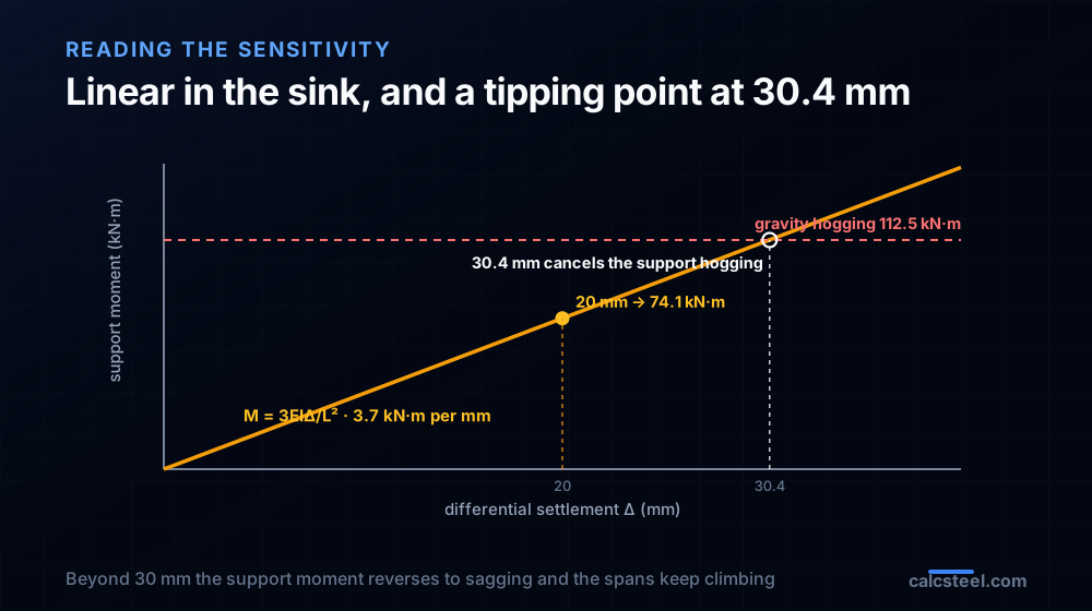
- Linear in the settlement. Every extra millimetre of sink adds about 3.7 kN·m over the support. Ten millimetres invent 37 kN·m, thirty millimetres invent 111 kN·m. There is no threshold below which settlement is free; it is proportional all the way down.
- Proportional to stiffness. Swap the IPE 400 for a section with twice the I and the same 20 mm sink invents twice the moment, near 148 kN·m. The counterintuitive lesson is that a beefier beam is more sensitive to settlement, not less, because it fights the imposed movement harder. Deflection and settlement moment pull in opposite directions when you size a member.
- Inversely proportional to span squared. Halve the span to 3 m and the same sink invents four times the moment. Long continuous spans tolerate settlement gracefully; short stiff bays do not, which is why settlement is a headache in things like closely spaced pier caps and short-bay industrial floors.
The most useful single number is the tipping point. Our gravity hogging was 112.5 kN·m. Setting 3EIΔ/L² equal to that and solving for Δ gives about 30.4 mm: at that settlement the invented sagging exactly cancels the gravity hogging, the interior support moment passes through zero, and the continuous beam behaves for that instant like two independent simply supported spans. Push the sink beyond 30 mm and the support moment reverses to net sagging while the span moments keep climbing toward the wL²/8 = 112.5 kN·m of a simple span. Settlement is not monotonically helpful; it relieves the support up to a point and then starts loading the spans hard. Since the invented moment is locked in, it also stacks with the worst load combination, and the settlement case belongs in the envelope, not as an afterthought.
When settlement matters, and what to do about it
Not every structure needs a settlement check, and knowing which do is half the skill. The rule follows straight from the physics.
- Determinate structures are immune. A simply supported beam, a cantilever, a statically determinate truss: none of them invent any force from support movement, because they have the freedom to accommodate it. If your structure is determinate, differential settlement is a serviceability and alignment issue, not a strength one.
- Continuous and rigid-frame structures are exposed. Continuous beams, rigid frames, fixed arches, anything with redundant supports, all invent forces from differential settlement. The more redundant the structure and the stiffer its members, the more it invents. A rigid portal frame carries settlement moments into its columns and bases just as our beam carries them into its spans.
- Soft ground and mixed foundations raise the risk. Settlement is largest and least even over compressible soils, where footings bear on different strata, or where a heavily loaded column neighbours a lightly loaded one. That is precisely where the geotechnical report earns its fee.
The engineer's toolkit against settlement is a short list. Bound it: the foundation design limits differential settlement to an allowable angular distortion, and you design the superstructure for that bound as an imposed deformation. Design for it: include a settlement load case in the combinations and let it sit in the envelope, since it is a locked-in effect that does not conveniently disappear. Soften the structure: paradoxically, a more flexible framing (or a genuinely pinned detail) invents less moment for the same sink, which is one reason not every joint should be made rigid. And detail for relevelling where the ground is doubtful, with shimmable bearings or jacking points, so a moment that grew can be released. The one thing you cannot do is ignore it, because the beam will not.
Common mistakes and FAQ
Settlement trips up careful engineers in a handful of repeatable ways. Run this list before you trust a settlement calculation.
- Assuming zero load means zero moment. The whole point of settlement is that an unloaded indeterminate beam is still stressed. If your model shows no moment under a support movement, either the structure is determinate or the movement was not actually imposed.
- Using uniform settlement instead of differential. Only the relative sink between supports invents force. Subtract the common movement first; a beam whose supports all drop 20 mm together is unstressed.
- Getting the sign backwards. A support that sinks invents sagging over itself, opposite to the hogging a downward load makes there. Assume it always adds to the gravity moment and you can be badly wrong, in either direction.
- Forgetting that stiffer is worse. The instinct to fix a settlement problem by adding steel backfires: a larger section invents a larger moment for the same sink. Reducing stiffness, or releasing a support, is often the real cure.
- Leaving settlement out of the combinations. The invented moment is locked in and adds to the governing load case. Checking gravity alone and settlement alone, but never together, misses the envelope where the span governs.
Does settlement always relieve the support moment?
Only up to a point, and only for downward settlement of an interior support under gravity. On our beam it relieved the hogging up to about 30 mm, then reversed it. Settlement of an end support, or upward movement, or a different load pattern, can just as easily add to the peak moment. It has to be checked, not assumed.
How much settlement is allowable?
That is a foundation and serviceability decision, usually expressed as an angular distortion between adjacent supports, with common framed-building limits around L/500 to L/300 depending on what the structure and its finishes can tolerate. The structural job is to take that allowable differential as an imposed deformation and confirm the members still pass under the full combination.
Why does EI appear when there is no deflection limit involved?
Because settlement moment is a stiffness effect, not a strength one. The beam resists the imposed movement in proportion to how stiff it is, so EI sets the force. It is the same EI that governs deflection under load, appearing here as the source of an invented force rather than a limit on movement.
Key takeaways
You have watched a beam invent a real bending moment from a movement with no load behind it, and you can now say exactly why, how big, and what to do about it.
- Only indeterminate structures invent forces from settlement. A determinate beam follows the support and stays unstressed; a continuous beam is forced to bend, and bending is moment. Redundancy is the whole difference.
- The moment is 3EIΔ/L². It grows with the beam's stiffness EI, falls with the square of the span, and is linear in the differential settlement Δ. Stiff short spans suffer most.
- On our beam, 20 mm invents 74.1 kN·m of sagging over the settled support, engine-verified to three decimals, and it points opposite to the gravity hogging.
- Settlement redistributes, it does not reduce. The same 20 mm relieved the interior hogging 66% but drove the span sagging up 49%, and the governing section moved from the support into the span. Never assume settlement is conservative.
- Only differential settlement counts, and it is a locked-in effect that belongs in the load combinations, not an afterthought.
Do one by hand, then check it in seconds. Put a span, a section and a load into the free beam calculator and feel how stiffness drives both deflection and settlement moment. When the structure grows to a real frame, CalcSteel runs the same FEM engine on the whole thing in your browser, on a genuinely free plan, with every diagram, section class and code check included. Students get everything unlocked through CalcSteel Education, free. The forces a settling column invents are real, but they are also, once you have the formula, entirely predictable.
Sources
Try CalcSteel for free
Model, analyze and design steel structures in your browser. No install, no signup.
Open the 3D editor