Shear Flow in Built-Up Members: Sizing the Weld That Holds a Plate Girder Together

Shear flow, q = VQ/I, is the force per unit length that the connectors of a built-up member have to carry: the weld or the bolts that make separate plates act as one beam. Every student learns the formula and sizes the weld from it. Run it on a real welded plate girder and the fillet the shear flow asks for is under a millimetre, so the code minimum, a wheel load, or fatigue is what truly sizes it. This guide derives q, sizes the weld on the CalcSteel engine, and shows the three things that actually govern the connector.
Key takeaways
- Shear flow is q = VQ/I, a force per unit length (N/mm, numerically the same as kN/m). It is the demand on the connectors, weld or bolts, that hold a built-up member together as one beam. Q is the first moment of the connected piece about the neutral axis, not of the whole section.
- On a real welded plate girder, web 1000 x 10 and flanges 300 x 20, the CalcSteel engine returns V = 360 kN at the support for a 12 m span under 60 kN/m. With Q = 3060 cm3 and I = 395,493 cm4 that is a shear flow of 278.5 N/mm at the flange-to-web junction.
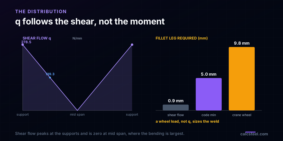
- Two fillet welds share that flow, 139.3 N/mm each. The leg it requires is 0.91 mm by AISC or 0.78 mm by Eurocode. The code minimum fillet for a 10 mm web is 5 mm, so the minimum governs: the shear flow uses only 18% of a minimum weld.
- Shear flow follows the shear diagram: largest at the supports, 139.3 N/mm at the quarter points, zero at mid span. That is why intermittent or tapered welds are legitimate, and why the flange weld is heaviest exactly where the bending stress is smallest.
- What actually sizes the weld is the code minimum, a crane wheel patch load that adds a vertical flow and pushes the fillet to a governing 9.8 mm leg, or fatigue. In bolted and riveted built-up members the same q sets the fastener pitch directly.
The weld that shear flow asks for is smaller than you think
A plate girder is not rolled. It is fabricated: two flange plates and a web plate, welded into one deep I-shape so it can span further and carry more than any rolled beam in the catalogue. The whole idea only works if the three plates act as one member, and what forces them to act as one is the pair of welds running along each flange-to-web junction. Size those welds wrong and the girder either delaminates into three loose plates or, more often, wastes weld metal by the tonne.
The quantity that sizes them is shear flow, q = VQ/I. Every mechanics-of-materials course teaches it, usually with a picture of planks sliding over each other, and then sets a homework problem that ends with a weld size or a nail spacing. This article does the same calculation, but on a real welded girder run through the CalcSteel engine, and reports what the engine actually returns. The punchline is worth stating up front: the fillet the shear flow demands comes out under one millimetre, far below any weld you could physically lay. The minimum-size rule, a wheel load, or fatigue is what really governs. Knowing which, and why, is the difference between a girder detail that is right and one that is merely full of weld.

What shear flow is, and the units that give it away
When a beam bends, the bending stress varies over its depth, larger near the flanges, zero at the neutral axis. Because that stress changes from one cross-section to the next along the span, the top part of the beam is being pushed harder on one face than the other, and it would slide relative to the bottom part if nothing held them together. In a solid rolled beam the steel itself resists that sliding. In a built-up member the connectors do, and the intensity of the sliding force they must resist is the shear flow:
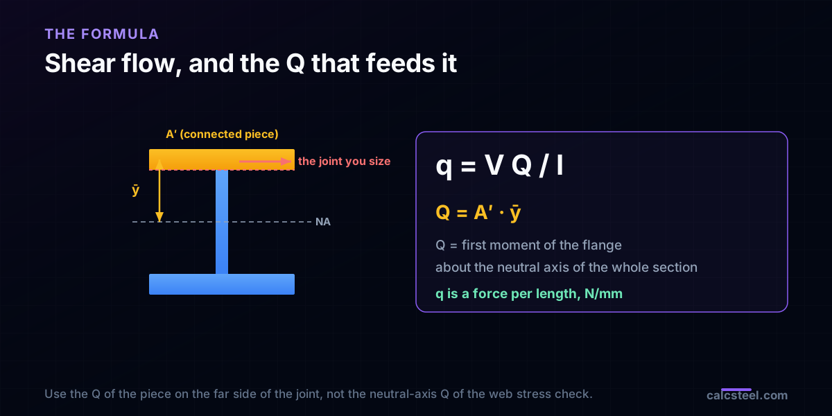
q = V Q / I.
Here V is the transverse shear at the section, I is the moment of inertia of the whole built-up cross-section about its neutral axis, and Q is the first moment of area of the part being connected, taken about that same neutral axis. The result q has units of force per unit length, newtons per millimetre or kilonewtons per metre, which happen to be numerically identical. That unit is the tell. Shear stress is force per area; shear flow is force per length, because it is a stress already multiplied through the thickness of the joint. When a formula hands you N/mm, it is asking how much weld or how many bolts you need per metre of member, not what stress the steel sees.
Where the sliding force comes from
It is worth being precise about the physics, because the same idea gets used later for bolts, cover plates and cap channels. Take two adjacent cross-sections a small distance apart. The flange between them carries a slightly larger bending force at one section than at the other, and the difference has to go somewhere. It flows down into the web across the horizontal cut where flange meets web. That horizontal force, divided by the length over which it acts, is the shear flow.
Two consequences follow. First, shear flow exists only where there is a change in bending, and the rate of change of bending moment is precisely the shear force V. No shear, no flow: at the point of maximum moment, where V passes through zero, the shear flow at the flange is zero even though the bending stress is at its peak. Second, the horizontal shear on that cut is matched by an equal vertical shear on the perpendicular face, the complementary shear that shows up as the familiar VQ/It shear stress in the web. Shear flow and shear stress are the same phenomenon read two ways: q is what the connector feels, VQ/It is what the material feels. For the full picture of how V and the moment vary along a span, the companion guide on shear and moment diagrams is the place to start.
The one mistake that ruins the number: choosing the wrong Q
Everything in q = VQ/I is unambiguous except Q, and Q is where most errors live. Q is the first moment of area of the material on one side of the cut you are checking, taken about the neutral axis of the whole section. The cut is the joint you are designing. For a plate girder weld you are cutting at the flange-to-web line, so Q is the first moment of the flange alone:
Q = A' y-bar = (flange area) x (distance from the flange centroid to the neutral axis).
This is not the Q that gives the maximum shear stress. The largest shear stress in the web uses Q taken at the neutral axis, which includes the flange plus half the web and is bigger. Feed that larger Q into a weld calculation and you oversize the weld; it belongs to the web stress check, not the flange connector. The rule is simple and unforgiving: Q is always the first moment of the piece on the far side of the joint you are connecting. Connect a cover plate, use the cover plate's Q. Connect a cap channel, use the channel's Q. Connect a flange, use the flange's Q. Get the cut right and the rest is arithmetic.
A real plate girder, measured on the engine
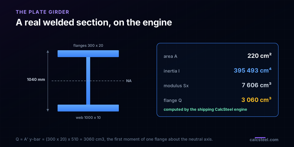
Numbers make this concrete. Take a welded plate girder built from a web plate 1000 x 10 mm and two flange plates 300 x 20 mm, giving a total depth of 1040 mm. Assembled, that is a section the CalcSteel engine reports as A = 220 cm2, moment of inertia I = 395,493 cm4, and section modulus Sx = 7606 cm3. The first moment of one flange about the neutral axis is Q = A' y-bar = (300 x 20) x 510 = 3060 cm3, with the flange centroid sitting 510 mm from the neutral axis.
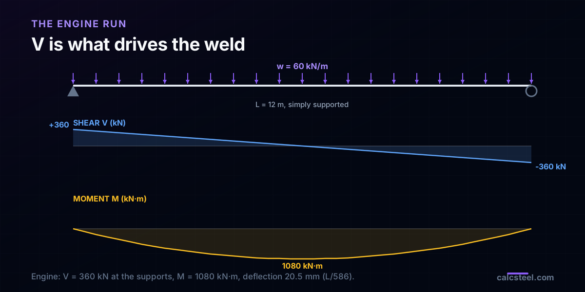
Span it 12 m, simply supported, under a service uniform load of 60 kN/m, the kind of load a transfer girder under a line of columns might see. The engine solves the beam and returns a support shear of V = 360 kN, a mid-span moment of M = 1080 kN.m, and a mid-span deflection of 20.5 mm, which is span over 586, comfortably inside a serviceability limit. The peak bending stress is M/Sx = 142 MPa. Each of those numbers matches the closed-form hand check to three decimals: wL/2 for the shear, wL squared over 8 for the moment, and 5wL to the fourth over 384EI for the deflection. That agreement matters, because the shear that drives the weld is the same V the engine just confirmed.
The shear the weld actually feels
With the section and the shear in hand, the shear flow at the flange-to-web junction is a single line:
q = V Q / I = (360,000 N)(3,060,000 mm3) / (3,954,930,000 mm4) = 278.5 N/mm.
Keep the units honest and it falls out cleanly: newtons times cubic millimetres over millimetres to the fourth is newtons per millimetre. So at each support the two flanges each shed 278.5 N/mm, equivalently 278.5 kN/m, into the web. That is the entire demand on the flange weld. Note what it is built from: the engine's shear, 360 kN, and the section's own geometry, Q and I. Change the load and V changes; change the plates and Q and I change; the weld demand tracks both. This is the number every plate-girder weld is sized against, and the next section sizes the weld to carry it.
Sizing the weld, and the reveal
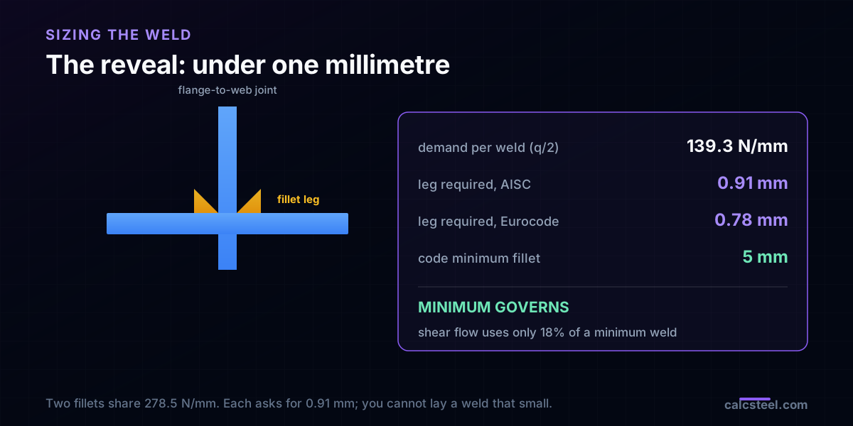
The flange is joined to the web by two fillet welds, one on each side of the web. They share the flow, so each weld carries 278.5 / 2 = 139.3 N/mm. A fillet weld's strength per unit length is its throat times the weld-metal shear strength; the throat is 0.707 times the leg. Using AISC with an E70 electrode, the design strength per millimetre of leg is 0.75 x 0.60 x 483 x 0.707 = 154 N/mm per mm of leg. Setting that equal to the demand:
leg = 139.3 / 154 = 0.91 mm.
Run the same check to Eurocode 3 and the required leg is 0.78 mm. Both answers are under a millimetre. You cannot lay a fillet that small, and no code would let you. The minimum fillet size for a 10 mm web, the thinner part joined, is 5 mm by AISC Table J2.4. A pair of 5 mm fillets carries about 1535 N/mm, so the shear flow of 278.5 N/mm uses just 18% of the smallest weld you are allowed to specify. That is the reveal, and it is not a quirk of this example: for almost any plate girder, the static shear flow leaves the flange weld idle. The weld exists, and it is continuous, but shear flow did not size it.
Shear flow follows the shear diagram, not the moment
Shear flow is not constant along the span, because V is not. For the simply supported girder, V is largest at the supports and falls linearly to zero at mid span, so the flange shear flow does the same: 278.5 N/mm at each support, 139.3 N/mm at the quarter points where V = 180 kN, and zero at mid span where V = 0. The weld is worked hardest at the ends and does almost nothing in the middle third.
This has two practical consequences. First, it is why intermittent fillet welds, short weld segments with gaps, and tapered weld schedules are legitimate and economical: you can put continuous weld near the supports and stitch weld through the low-shear middle, provided the stitch spacing satisfies the local flow and the minimum-length rules. Second, it defeats an intuition. The middle of the span is where the bending stress and deflection are largest, so it looks like the busy part of the beam. For the flange weld it is the quietest part. The weld peaks over the supports, where the moment is zero. Shear flow answers to V, and V is the slope of the moment, not the moment itself.
What actually sizes the flange weld
If shear flow uses 18% of the minimum weld, what does the design? Three things, in roughly this order.
The minimum fillet size. For most plate girders under distributed load, the answer is simply the code minimum continuous fillet, driven by the plate thicknesses through AISC Table J2.4 or the Eurocode detailing rules, not by any force calculation. A 5 mm or 6 mm continuous fillet is specified because it is the smallest sound weld for those plates, and it is comfortably strong.
A local transverse load on the flange. The story changes the moment something bears directly on the flange over the web. A crane runway girder is the classic case: a wheel rolls along the top flange, and the wheel load must flow down through the flange-to-web weld into the web. That vertical flow adds to the horizontal shear flow as a vector. Take a 150 kN wheel dispersed over roughly 50 mm of web, a Design Guide 7 style local check, and the vertical flow is about 3000 N/mm. Combined with the 139.3 N/mm horizontal flow, the resultant per weld is about 1506 N/mm, which needs a 9.8 mm leg. Now the weld is genuinely designed, by the wheel, not by q alone. This is why crane girder flange welds are heavy and continuous while ordinary girder flange welds are minimums.
Fatigue. Anything that cycles, crane girders, bridge girders, machine supports, is usually governed not by static strength at all but by the fatigue category of the flange-to-web detail. A continuous automatic fillet is a better fatigue detail than a stitch weld, which is one more reason a lightly loaded crane girder still gets continuous weld. For the related question of what the web needs where a load lands on it, see web stiffeners under a concentrated load.
Where shear flow does size the connector: bolts, rivets, nails
Shear flow earns its keep as a design driver in the other family of built-up members: those held together by discrete fasteners rather than continuous weld. There the same q, but now divided among individual connectors, sets the spacing directly. If each connector line offers a capacity R and there are n shear planes per position, the fastener pitch is:
s = n R / q.
Take the same girder, but imagine the flanges bolted to the web through angles rather than welded, the way riveted plate girders were built for a century. With M20 grade 8.8 bolts in single shear, about 94 kN each, and two planes at the junction, the pitch the shear flow allows is s = 2 x 94.1 / 0.279 = 676 mm. In this girder even that is generous: the code maximum spacing to keep the plates from buckling between fasteners is around 140 mm, so the detailing rule still wins. But shrink the section, move the connected piece further from the neutral axis so its Q grows, or drop to a low-capacity connector like a rivet or a nail, and s = nR/q lands on a real, close spacing. That is the regime of the timber built-up beam, the nailed box section and the historic riveted girder, where the fasteners march along the flange at 75 to 150 mm precisely because shear flow demanded it. For the strength of the bolts themselves in the connected plate, the guides on bolt bearing and tear-out and prying action carry it further.
Five ways a shear-flow check goes wrong
- Using the neutral-axis Q for a flange weld. The Q that maximises web shear stress includes half the web and is larger. It belongs to the VQ/It stress check, not to the connector. For the weld, use the first moment of the flange alone.
- Forgetting the connectors share the flow. Two flange welds carry q together, so each sees q/2. Design each for the full q and you double the weld. With four bolt lines, each sees q/4.
- Sizing on the mid-span shear. Shear flow is largest at the supports, where V is largest, and zero at mid span. Check the weld where V peaks, not where the moment does.
- Mixing force per length with force per area. q is N/mm, a line intensity; VQ/It is N/mm squared, a stress. They come from the same VQ but answer different questions. If your weld calculation carries a stress, something is off.
- Assuming q always governs. For a welded girder it usually does not: the minimum fillet, a patch load, or fatigue governs. Compute q, then check it against the minimum and against any local transverse load before you believe it sized anything.
A five-step routine for any built-up connector
The same sequence works whether the connector is a weld, a bolt group, a rivet line or a row of nails.
- Find V at the section. Read the shear from the analysis, and check it against wL/2 or the reaction. This is the only load-dependent input.
- Take the right Q. First moment of the piece on the far side of the joint, about the neutral axis of the whole section. Flange for a flange weld, cover plate for a cover plate.
- Use the assembled I. The moment of inertia of the complete built-up section, not of one plate.
- Compute q = VQ/I and divide among the connectors. Two welds, n bolt planes: each carries its share.
- Size, then reality-check. Get the weld leg or bolt pitch, then compare it to the code minimum fillet or maximum spacing, and to any local transverse or fatigue demand. Specify the governing one, and say which it is.
Try it live: get your V, then the shear flow follows
Shear flow is only ever one step from the shear diagram: once you know V at a section, q = VQ/I is arithmetic. The calculator below is the CalcSteel shear and moment diagram tool, free and with no login for the maths. Enter your span and loads, read V where you care about the connector, then multiply by your section's Q and divide by I to get the flow in N/mm, and the weld leg or bolt pitch from there.
From here, the neighbours worth reading are the shear and moment diagram guide for where V comes from, section modulus for how the same girder is checked in bending, and web stiffeners for what happens where a load lands on the web. Shear flow is the quiet thread through all of them: the force per length that turns a stack of plates into one member.
|V| max
30 kN
@ x = 6 m
M max (sagging)
45 kN·m
@ x = 3 m
M min (hogging)
-0 kN·m
@ x = 6 m
Reactions (kN)
R_A 30 · R_B 30
Simply supported beam — uniformly distributed load
Segment equations — x in m, from the left end
0 m ≤ x ≤ 6 m
V(x) = 30 − 10·x [kN]
M(x) = 30·x − 5·x² [kN·m]
Profiles that resist this moment
Md = 45 kN·m → required Wx = Md / (fy/γa1) = 45 kN·m / (250/1.1) = 198 cm³
Bending screen (Wx ≥ Md/(fy/γa1), NBR 8800 γa1 = 1.10 — AISC 360 φb = 0.90 is nearly identical); plastic Zx is valid for compact sections only. δ is the elastic deflection of THIS loading with E = 200 GPa and the section's Ix (loads taken at service value). LTB, shear, compactness and code deflection limits are verified on the profile page and in the 3D editor. "Open in 3D editor" recreates THIS beam — span, supports and every load — with the profile already assigned.
Try CalcSteel for free
Model, analyze and design steel structures in your browser. No install, no signup.
Open the 3D editor