Prying Action in Tension Connections: the Extra Bolt Force the Geometry Creates
When a bolted flange bends, the bolt carries more tension than the load you applied. This guide shows where that extra force comes from, how the AISC Manual Part 9 method turns flange thickness and bolt gage into a real number, and a worked WT hanger where prying quietly adds 30 percent to every bolt, with the bolt tension strength taken straight from the CalcSteel connection engine.
Key takeaways
- Prying action is extra bolt tension the connection geometry invents. A flexible flange bends, its edge bears back on the support, and that reaction levers additional force into the bolt: B equals the applied tension T plus the prying force Q.
- The driver is flange stiffness, not the bolts. AISC Manual Part 9 collapses it into one target thickness tc: when the actual flange thickness t is below tc the flange hinges and prying grows, when t reaches tc prying vanishes and the bolt sees only its share of the load.
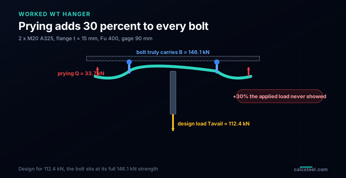
- In the worked WT hanger, two M20 A325 bolts with a 15 mm flange, prying adds Q equals 33.7 kN to each bolt, 30 percent on top of the 112.4 kN design load, so the bolt actually feels its full 146.1 kN tension strength.
- Thickening the same flange from 15 to 22 mm removes prying entirely and lifts the connection from 224.8 to 292.2 kN of tension, plus 30 percent, with no extra bolts and no higher grade.
- The bolt tension strength every number is checked against, phi Fnt Ab equals 146.1 kN per M20 A325, is the value returned by the CalcSteel connection engine. The prying force Q is the Part 9 hand method layered on top, because prying lives on the demand side, not the bolt.
Why the bolt sees more than the load you applied
You size a hanger for a 100 kN pull, split it between two bolts, check each bolt for 50 kN of tension, and it passes with room to spare. Then the connection loosens, the bolts stretch, and a failure investigation finds the bolts were carrying far more than 50 kN each. Nothing was overloaded on paper. The extra force did not come from the applied load. It came from the geometry of the flange, and it has a name: prying action.
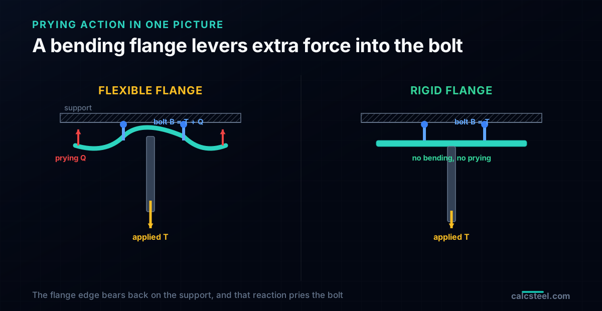
Prying is the one connection effect where the structure adds load to the bolt that never appears in the free body you drew. It happens whenever a bolt pulls on a plate or a flange that is free to bend, a WT hanger, a bolted end plate, a double angle in tension, a base plate in uplift. The flange flexes, its outer edge pushes back against the support, and that contact reaction pries the bolt like a claw hammer pulling a nail. The bolt tension is no longer the applied load over the number of bolts. It is that share plus a prying force Q that the flange thickness and the bolt position decide.
This guide is about turning Q into a number. Every capacity here was checked against the CalcSteel connection engine, which returns the bolt tension strength phi Fnt Ab exactly, and the prying force is computed with the AISC Steel Construction Manual Part 9 method, cross checked by hand. We wrote it for three readers. If you are a student, prying is the topic your connections course mentions in one line and never quantifies. If you are a practising engineer or a freelance calculista, jump to the worked example and the thickness sweep, where a few millimetres of flange decide 30 percent of your bolt force. And if you just want the rule: a thin flange makes the bolt carry more than the load, and you fix it with steel in the flange, not more bolts.
Prying sits next to the plate limit states in the bolted connection design guide, but it is a different failure path. Bearing and net section are the plate giving way. Prying is the bolt overloaded in tension by a flange that will not stay flat.
Where the extra force comes from
Start with the mechanics, because prying only makes sense once you see the flange as a beam. Take a structural tee hung from a support: the stem is pulled down with a tension load, the flange is bolted up to the support on each side of the stem.
A rigid flange has no prying
Imagine the flange is infinitely stiff. It cannot bend, so it stays flat against the support and lifts uniformly. The only thing holding it up is the bolts, so each bolt carries exactly its share of the applied load, T equals the total tension over the number of bolts. There is no contact anywhere else, no prying, and the bolt tension is the number you expected. This is the ideal every thick flange approaches.
A flexible flange bends and pushes back
Now make the flange realistic. As the stem pulls, the flange bends in double curvature: it hinges near the stem where it is restrained, and it hinges again at the bolt line. Between the bolt and the free edge, the flange rotates so that its outer edge presses back down on the support. That contact force is the prying force Q. It is a reaction the flange invents by bending, and it has to be resisted somewhere.
The lever closes on the bolt
Take moments about the stem face and the picture snaps into place. The applied tension T acts at the stem, the prying force Q acts out at the flange edge, and the bolt sits between them. For the flange to be in equilibrium, the bolt must hold down both, so the bolt tension is B equals T plus Q. The flange edge and the bolt form a lever exactly like the claw of a hammer: the further and softer the flange overhang, the more the edge pries, and the more the bolt is stretched beyond the load you applied. Prying is real, mechanical, and entirely set by how the flange bends.
The five dimensions that set the lever
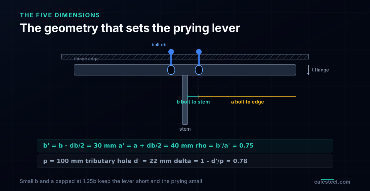
Because prying is a bending problem, it is controlled by geometry, and the AISC Manual Part 9 method reduces that geometry to a handful of lengths. Learn these five and the equations read themselves.
- b, the distance from the bolt centreline to the face of the stem or web. This is where the flange is restrained, so b is the lever arm of the bolt against the applied load. A small b, bolts tucked close to the stem, means a short lever and little prying.
- a, the distance from the bolt centreline to the edge of the flange. This is where the prying contact acts. AISC caps the value used in the maths at a equals 1.25 b, because a very wide overhang does not keep prying growing without limit.
- b prime equals b minus db over 2 and a prime equals a plus db over 2, the same lengths shifted to the edge of the bolt shank. These are the arms that actually appear in the equations, with db the bolt diameter.
- rho equals b prime over a prime, the ratio that measures how much lever the flange edge has over the bolt. A big rho, bolts far from the stem and close to the edge, means heavy prying.
- p, the tributary length of flange assigned to one bolt along the connection, and delta equals 1 minus d prime over p, which knocks the flange strength down for the bolt hole of diameter d prime that removes material at the critical line.
For the worked hanger below, with a bolt gage g equals 90 mm across a 10 mm stem and a 150 mm wide flange: b equals (90 minus 10) over 2 equals 40 mm, a equals (150 minus 90) over 2 equals 30 mm. Then b prime equals 40 minus 10 equals 30 mm, a prime equals 30 plus 10 equals 40 mm, rho equals 0.75. With a 100 mm tributary and a 22 mm standard hole, delta equals 1 minus 22 over 100 equals 0.78. Every prying number in this article is built from those five values.
The AISC Manual Part 9 method, term by term
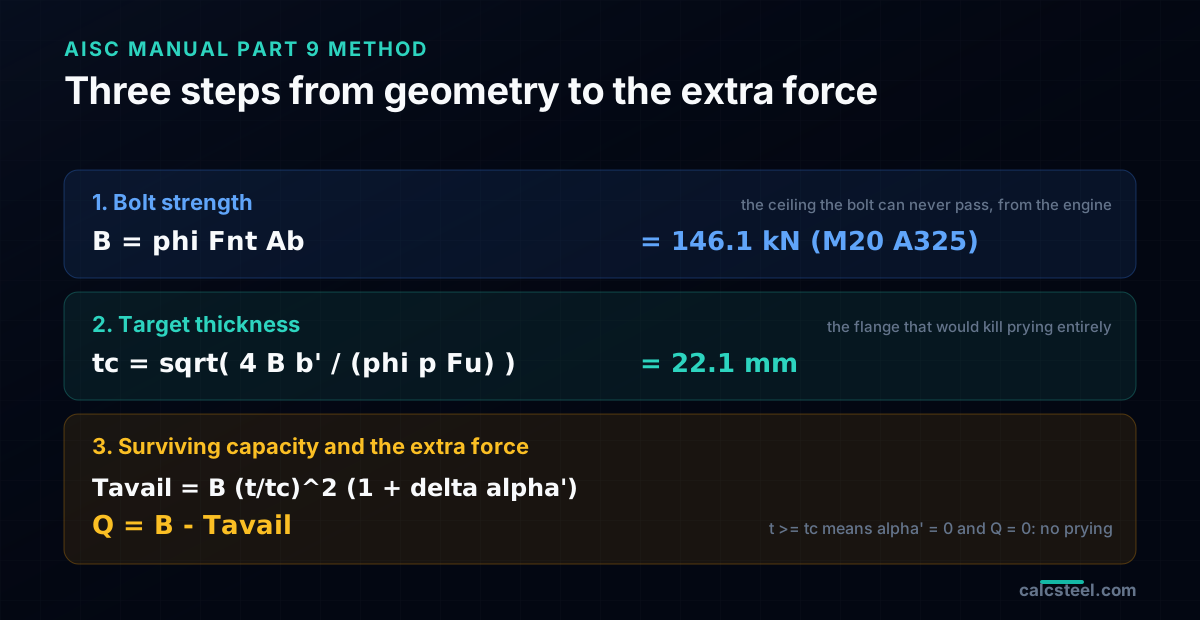
The AISC Steel Construction Manual, Part 9, gives a compact way to check prying without solving the flange as a frame every time. It compares the flange you have against the flange you would need to make prying disappear, then reports how much bolt capacity survives. Three quantities do all the work.
Step 1: the bolt tension strength B
B is the available tension strength of one bolt, B equals phi Fnt Ab, with phi equals 0.75, Fnt the nominal tensile strength, and Ab the nominal bolt area. This is the ceiling the bolt can never exceed, prying or not, and it is exactly what the CalcSteel connection engine returns. For an M20 A325, Fnt equals 620 MPa and Ab equals 314.2 square mm, so B equals 0.75 times 620 times 314.2 over 1000 equals 146.1 kN.
Step 2: the target thickness tc
tc is the flange thickness that would let the bolt reach its full strength B with no prying at all. It comes from setting the flange plastic moment equal to the moment the bolt force applies over the arm b prime:
tc equals square root of (4 B b prime over (phi p Fu)), with phi equals 0.90 for flange bending and Fu the flange strength.
For the worked hanger, tc equals square root of (4 times 146.1 times 30 over (0.90 times 100 times 400)) equals 22.1 mm. Read tc as the honest answer to a designer question: how thick would this flange have to be so the geometry stops stealing capacity? Here, 22.1 mm.
Step 3: how much capacity survives
Compare the flange you actually have, thickness t, against tc through a factor alpha prime that measures how hard the flange is working in bending:
alpha prime equals (1 over (delta (1 plus rho))) times ((tc over t) squared minus 1), clamped between 0 and 1.
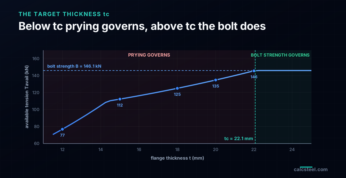
Then the available tension per bolt, prying included, is T avail equals B times (t over tc) squared times (1 plus delta alpha prime). When t reaches tc, alpha prime is 0 and T avail equals B: no prying. When t is thin, alpha prime saturates at 1 and T avail collapses. The prying force at that design load follows straight from equilibrium: Q equals B minus T avail, the gap between what the bolt can take and what the connection is allowed to apply. That gap is the extra force the geometry created.
Worked example: a WT hanger where prying adds 30 percent
Put the method on a real detail. A structural tee hangs a tension load from the underside of a beam, bolted through its flange with two M20 A325 bolts, one each side of the stem. Flange thickness t equals 15 mm, flange strength Fu equals 400 MPa, stem thickness 10 mm, bolt gage g equals 90 mm, flange width 150 mm, standard holes d prime equals 22 mm, tributary p equals 100 mm per bolt.
Step 1: geometry
b equals 40 mm, a equals 30 mm, b prime equals 30 mm, a prime equals 40 mm, rho equals 0.75, delta equals 0.78. All five lengths as computed in the previous section.
Step 2: bolt strength and target thickness
B equals 146.1 kN from the engine. tc equals square root of (4 times 146.1 times 30 over (0.90 times 100 times 400)) equals 22.1 mm. The flange you have, 15 mm, is well below the 22.1 mm that would kill prying, so prying is significant and you must account for it.
Step 3: how much capacity the flange keeps
alpha prime equals (1 over (0.78 times 1.75)) times ((22.1 over 15) squared minus 1) equals 0.85. Since it lands between 0 and 1, use it directly. Then T avail equals 146.1 times (15 over 22.1) squared times (1 plus 0.78 times 0.85) equals 112.4 kN per bolt. The 15 mm flange lets each bolt be loaded to only 112.4 kN, not its full 146.1 kN.
Step 4: the prying force
Q equals B minus T avail equals 146.1 minus 112.4 equals 33.7 kN. That is the extra force the geometry creates. At the design load of 112.4 kN per bolt, the bolt actually carries 112.4 plus 33.7 equals 146.1 kN, its full tension strength. Prying added 30 percent on top of the applied load, and it never appeared in the applied free body. A designer who checked 112.4 kN against the 146.1 kN bolt strength and stopped there would have missed a bolt sitting exactly at its limit.
Step 5: the connection
Two bolts carry 2 times 112.4 equals 224.8 kN of applied tension. Had the flange been rigid, the same two bolts would carry 2 times 146.1 equals 292.2 kN. Prying cost this connection 67.4 kN, almost a full extra bolt of capacity, and it cost it in the flange, not the fasteners.
How much prying, as a function of flange thickness
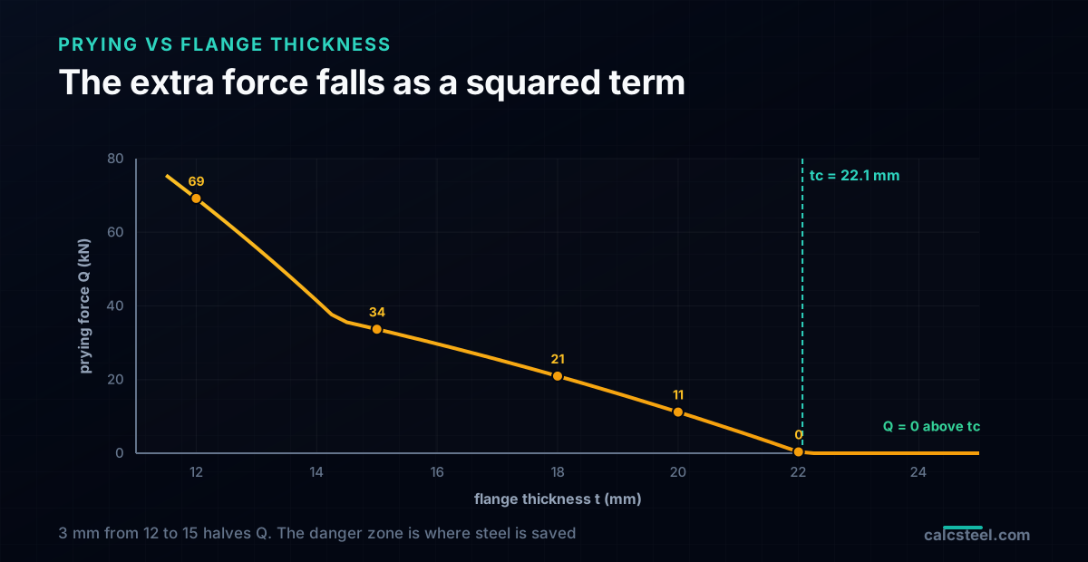
The single most useful thing to internalise is how fast prying changes with flange thickness. Hold the geometry, the bolt and the load fixed, and sweep the flange thickness t from thin to thick. Q falls away steeply as t climbs toward tc equals 22.1 mm, and past tc it is gone:
- t equals 12 mm: alpha prime saturates at 1, T avail equals 76.9 kN, Q equals 69.2 kN. Prying adds 90 percent. A bolt designed for 77 kN carries 146 kN.
- t equals 15 mm (the worked flange): T avail equals 112.4 kN, Q equals 33.7 kN, prying adds 30 percent.
- t equals 18 mm: T avail equals 125.1 kN, Q equals 20.9 kN, prying adds 17 percent.
- t equals 20 mm: T avail equals 134.9 kN, Q equals 11.2 kN, prying adds 8 percent.
- t equals 22 mm (just under tc): T avail equals 145.7 kN, Q equals 0.4 kN, prying is essentially gone.
- t equals 24 mm (above tc): T avail equals 146.1 kN, Q equals 0, no prying.
The shape is the lesson. Prying is not linear in thickness, it is a squared term through (tc over t) squared, so it punishes thin flanges brutally and then disappears almost as a step near tc. A 3 mm change from 12 to 15 mm halves the prying force, while the same 3 mm from 18 to 21 nearly erases it. This is why prying is dangerous: it is invisible in the applied load and it grows fast exactly where designers economise, in the flange thickness.
The target thickness tc is the whole design decision
Everything above collapses to one comparison: your flange thickness t against the target thickness tc. tc is the flange that makes the bolt reach its full strength B with zero prying, and it is the cleanest design target in the whole method.
- If t is greater than or equal to tc, the flange is stiff enough. There is no prying, each bolt carries only its share of the applied load, and the connection is limited purely by the bolt strength B. The available tension is 2 B for the pair.
- If t is less than tc, the flange hinges, prying appears, and the available tension per bolt drops to T avail below B. The thinner the flange, the steeper the drop.
That turns prying design into a choice with four levers, in the order you should reach for them:
- Thicken the flange to tc. The direct fix. In the worked hanger, moving from 15 to 22 mm lifts the connection from 224.8 to 292.2 kN, a 30 percent gain in tension for 7 mm of plate, with no extra bolts. Often the cheapest change on the drawing.
- Move the bolts toward the stem. A tighter gage cuts b, shortens the lever, and lowers rho, so prying falls even at the same thickness. Watch wrench clearance and the stem fillet.
- Do not overhang the flange edge. Beyond a equals 1.25 b the extra width buys nothing against prying and only adds edge that pries. Trim it.
- Add bolts or raise the grade. More or stronger bolts raise B, so the same applied load is a smaller fraction of capacity. This helps the bolt, but it does not stop the flange bending, so reach for it last.
The instinct to add bolts is usually the wrong first move. Prying is a stiffness problem, so the honest fix is stiffness: thicker flange, tighter gage. The same logic drives base plate design, where the plate thickness against the anchor rods is governed by an almost identical bending check, and the CalcSteel base plate module sizes the plate the same way.
Five mistakes that hide the extra bolt force
Every one of these makes a prying check pass on paper while the real bolt is overloaded. None of them throws an error, which is exactly why prying keeps surprising careful engineers.
- Ignoring prying entirely. The biggest one. Dividing the applied load by the number of bolts and checking that against B assumes a rigid flange. On a thin flange it can understate the bolt tension by 30, 50, even 90 percent, as the sweep shows.
- Using b and a instead of b prime and a prime. The equations use the shifted arms, b prime equals b minus db over 2 and a prime equals a plus db over 2. Skipping the db over 2 shift moves the lever and understates prying.
- Forgetting the a equals 1.25 b cap. A wide overhang does not keep helping. Using the full a when it exceeds 1.25 b overstates how much the edge resists and hides prying. Cap a at 1.25 b in the maths.
- Reading Fu off the bolt, not the flange. tc and the flange bending use the flange strength Fu, around 400 to 450 MPa for structural steel, not the bolt tensile strength of 620 MPa or more. The flange is what bends.
- Detailing a wide gage for wrench access. Comfort at the spanner costs capacity. A larger gage means a larger b, a longer lever, and more prying. Keep the bolts as close to the stem as the fillet and the wrench allow.
Where prying shows up, and where it hides
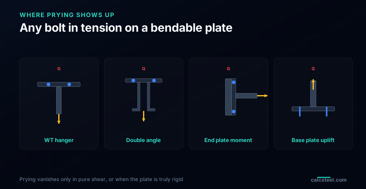
Prying is not a WT hanger curiosity. It appears in any tension connection where a bolt pulls on a flange or plate that can bend, and it is easy to miss because the applied free body never shows it.
WT and double angle hangers
The textbook case, and the one worked above. A tee or a pair of angles hung in tension, bolted through the flange or the outstanding legs. The thinner the flange or the leg, the more it pries. Double angles pry through both legs, so check the leg that bends.
Bolted end plate moment connections
The most important practical case. In a bolted end plate, the beam flange force pulls the end plate against the column, and the bolts near the tension flange pry exactly like a hanger. Prying can add a large fraction to those bolts, and every end plate design method, from AISC Design Guide 4 to Eurocode 3 T stub, is a prying calculation at heart. If you detail moment connections, this is the case that matters.
Base plates in uplift
A column base under net uplift pulls the anchor rods, and a thin base plate bends and pries the rods just like a flange pries a bolt. The base plate design check for plate thickness against the rods is the same bending problem in another costume.
Where it hides
Prying vanishes only when the flange is genuinely rigid relative to the bolt, t at or above tc, or when the load is pure shear with no bolt tension. Slip critical joints, shear tabs and bearing splices in shear do not pry. The moment you have bolts in tension against a bendable plate, prying is on the table, and the applied load will not warn you.
Check it live, and let the engine hold the bolt strength
The fastest way to feel prying is to watch the bolt strength stay fixed while the geometry moves the demand. The calculator below is the CalcSteel bolt tool, free and with no login for the maths. It returns the bolt tension and shear strength from the same connection engine every capacity in this article was checked against: phi Fnt Ab equals 146.1 kN for an M20 A325, with the pretension and combined shear interaction alongside.
That engine number is the ceiling B in the prying method. The prying force Q is the Part 9 hand calculation layered on top, because prying lives on the demand side of the check, not inside the bolt: it is extra tension the flange delivers, and you compare the total B equals T plus Q against the bolt strength the tool gives you. Set the grade and diameter to read B, then take your flange thickness, gage and edge distance through the tc comparison above to see how much of that B the geometry lets you use.
In a full model the work multiplies, every bolt, every plate, every load combination, with prying on the tension bolts and bearing, shear and block shear on the plate. That is what the CalcSteel connection engine automates, and where you still bring the judgement: an eccentric pull, a stiffened end plate, or a flange too thin to trust. Take the same joint into the full bolted connection design workflow, where prying sits beside the plate limit states and the connection is sized for whichever governs.
Tightening torque
610 N·m
K±25%: 457–762 N·m
Bolt preload (clamp)
152.4 kN
34,257 lbf
Tensile stress area Aₛ
244.8 mm²
proof 203.2 kN
Proof / yield load
203.2 kN
yield 220.3 kN
How this torque is built — T = K · F · d
Aₛ = 0.7854·(d − 0.9382·P)² = 244.8 mm² (P = 2.5 mm) · engine table Aₛ = 245 mm²
Fₚ (proof) = Aₛ·Sp = 244.8·830 = 203.2 kN
F (preload) = 75%·Fₚ = 152.4 kN = 34,257 lbf
T = K·F·d = 0.20 · 152.4 kN · 20 mm = 610 N·m = 450 lbf·ft
Nut-factor scatter is real — ±25 % on K (Bickford)
Same preload, torque range: 457 N·m … 762 N·mK = 0.20 → 0.150…0.250
Same torque, preload actually installed: 121.9 kN … 203.2 kNa high real K under-tensions the joint
Bolt shear + tension capacity — live from the CalcSteel connection engine
These come straight from engine/connections/boltData — the same NBR 8800:2024 nominal strengths the 3D-editor connection design uses. Torque installs the clamp; this is what the bolt can carry. Single bolt, one shear plane.
Fnv (NBR)
450 MPa
Fnt
750 MPa
φRn — shear
71.6 kN
φRn — tension
119.3 kN
fub = 1000 MPa · Ab = 314 mm² · Aₛ = 245 mm² · φ = 0.65
Structural joints — minimum pretension Tb (NBR 8800 · AISC/RCSC)
Slip-critical and pretensioned connections do not aim for a % of proof load — the code fixes a minimum bolt tension Tb = 0.70·Fu·Aₛ per diameter. Below is that value for the two structural grades at M20, plus the K·Tb·d wrench torque (turn-of-nut and DTI are the code-preferred methods — torque is calibration-only).
ASTM A325 (≈ ISO 8.8)
Tb = 142.2 kN = 31,974 lbf
torque ≈ 569 N·m = 420 lbf·ft
ASTM A490 (≈ ISO 10.9)
Tb = 178.2 kN = 40,063 lbf
torque ≈ 713 N·m = 526 lbf·ft
Bolt torque chart — ISO 10.9 · Plain / as-received (dry) · 75% proof
| Size | Aₛ (mm²) | Preload F | Torque (N·m) | Torque (lbf·ft) |
|---|---|---|---|---|
| 20.1 | 12.5 kN | 15 | 11 | |
| 36.6 | 22.8 kN | 36.5 | 27 | |
| 58 | 36.1 kN | 72.2 | 53 | |
| 84.3 | 52.5 kN | 126 | 93 | |
| 115 | 71.9 kN | 201 | 148 | |
| 157 | 97.5 kN | 312 | 230 | |
| 192 | 119.8 kN | 431 | 318 | |
| 245 | 152.4 kN | 610 | 450 | |
| 303 | 188.9 kN | 831 | 613 | |
| 353 | 219.4 kN | 1,053 | 777 | |
| 459 | 286 kN | 1,544 | 1,139 | |
| 561 | 349 kN | 2,094 | 1,544 | |
| 817 | 508.4 kN | 3,661 | 2,700 |
Nut factors are typical published values — real scatter is ±25 %. For critical joints, calibrate K on your actual fastener/lubricant. Torque values are guidance, not a substitute for a qualified design.
Sources
- 1.AISC Steel Construction Manual, Part 9 (Design of Connecting Elements), Prying Action
- 2.AISC 360-22 Specification for Structural Steel Buildings, Chapter J (Bolt Tension and Combined Tension and Shear)
- 3.Salmon, Johnson and Malhas, Steel Structures: Design and Behavior, connections chapters
- 4.Kulak, Fisher and Struik, Guide to Design Criteria for Bolted and Riveted Joints, second edition
- 5.ABNT NBR 8800 Design of steel and composite structures, bolt tension provisions
Try CalcSteel for free
Model, analyze and design steel structures in your browser. No install, no signup.
Open the 3D editor